
Service Manual Manual


Hydraulic System
8-20
G10-55A, G12-55A
Note: Avoid using excess force when clamping the
cylinder barrel in a vise. Apply only enough force to hold
the cylinder barrel securely. Excessive force can
damage the cylinder barrel.
5. Place the cylinder barrel in a soft-jawed vise or other
acceptable holding devise.
Note: When sliding the rod and piston assembly into the
cylinder barrel, prevent the threaded end of the cylinder
barrel from damaging the piston head. Keep the cylinder
rod centered within the barrel to prevent binding.
6. Carefully insert the cylinder rod assembly into the
cylinder barrel.
7. Screw the head gland into the cylinder barrel and
tighten with a spanner wrench. Refer to Section
8.8.5, “Cylinder Torque Specifications” for torque
specifications for the head gland.
8. If applicable, install new counter balance valve into
block on the cylinder barrel.
d. General Cylinder Installation
1. Grease the bushings at the ends of the hydraulic
cylinder. Using an appropriate sling, lift the cylinder
into it’s mounting position.
2. Align cylinder bushing and install pin, lock bolt or
retaining clip.
3. Connect the hydraulic hoses in relation to the labels
or markings made during removal.
4. Before starting the machine, check fluid level of the
hydraulic fluid reservoir and if necessary fill to full
mark with hydraulic oil.
5. Properly connect the batteries.
6. Start the machine and run at low idle for about one
minute. Slowly activate hydraulic cylinder function
in both directions allowing cylinder to fill with
hydraulic oil.
7. Inspect for leaks and check level of hydraulic fluid in
reservoir. Add hydraulic fluid if needed. Shut the
engine OFF.
8. Wipe up any hydraulic fluid spillage in, on, near and
around the machine, work area and tools.
9. Close and secure the engine cover.
10. Remove the Do Not Operate Tags from both the
ignition key switch and the steering wheel.
8.8.3 Cylinder Pressure Checking
Attach a 5000 psi (345 bar) gauge to the test port on the
P1 port on the hydraulic manifold to check the system
pressure. For more information, refer to Section 8.4.1,
“Hydraulic Pressures.”
Note: If a hydraulic cylinder pressure is greater than
main control valve pressure, increase main control valve
pressure by adjusting main relief. Generally, one half
turn clockwise will be adequate to check an individual
circuit. Activate circuit and if pressure is obtained turn
main relief counter clockwise one half turn. Re-check
main relief setting and adjust if necessary.
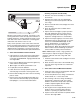
8.8.4 Steering Cylinders
The steer cylinder is attached to each axle center
housing. Steer cylinder service instructions are provided
in the following publications:
• Service Manual (P/N 31200240)
• Parts Manual (P/N 31200728)
MY4310
AXLE CENTER SECTION
STEERING CYLINDER