® SERVICE MANUAL G6-42P 9140-4002 November 2008 Starting Serial No. 0189001 thru 0189345 & 0160000230 thru Current CORPORATE OFFICE JLG INDUSTRIES, INC.
Operation & Safety Manual Keep this manual with machine at all times.
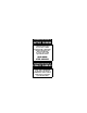
CALIFORNIA PROPOSITION 65 BATTERY WARNING Battery posts, terminals and related accessories contain lead and lead compounds, chemical known to the State of California to cause cancer and reproductive harm. WASH HANDS AFTER HANDLING! CALIFORNIA PROPOSITION 65 EXHAUST WARNING Diesel Engine exhaust and some of its constituents are known to the State of California to cause cancer, birth defects and other reproductive harm.
Revision Log Revision Log REVISION LOG November 25, 2008 - A - Original Issue of Manual 31200148 a
Read This First Read This First This manual is a very important tool! Keep it with the machine at all times. The purpose of this manual is to provide owners, users, operators, lessors, and lessees with the precautions and operating procedures essential for the safe and proper machine operation for its intended purpose. Due to continuous product improvements, JLG Industries, Inc. reserves the right to make specification changes without prior notification. Contact JLG Industries, Inc.
Read This First This product must comply with all safety related bulletins. Contact JLG Industries, Inc. or the local authorized JLG representative for information regarding safetyrelated bulletins which may have been issued for this product. JLG Industries, Inc. sends safety related bulletins to the owner of record of this machine. Contact JLG Industries, Inc. to ensure that the current owner records are updated and accurate. JLG Industries, Inc.
Read This First This Page Intentionally Left Blank d 31200148
Table of Contents Table of Contents TABLE OF CONTENTS Revision Log Read This First Operator Qualifications ...................................................... b Modifications ...................................................................... b Other Publications Available .............................................. c Table of Contents Section 1 - General Safety Practices 1.1 Hazard Classification system...............................................
Table of Contents Parking Procedure.......................................................... 3-9 Heater........................................................................... 3-10 3.3 Operator Seat.................................................................... 3-11 Seat Adjustments ......................................................... 3-11 Seat Belt ....................................................................... 3-13 3.4 Boom Angle and Extension Indicators .............................
Table of Contents Crane Hook...................................................................5-12 Bucket ...........................................................................5-14 Truss Boom...................................................................5-16 Boom Head-Mounted Winch.........................................5-18 6 ft (1,8 m) Mast with 48 or 72 in (1,2 & 1,8 m) Carriage ........................................................................
Table of Contents Dimensions.....................................................................
Section 1 - General Safety Practices SECTION 1 - GENERAL SAFETY PRACTICES 1.1 HAZARD CLASSIFICATION SYSTEM Safety Alert System and Safety Signal Words DANGER OW0010 DANGER indicates an imminently hazardous situation which, if not avoided, will result in death or serious injury. WARNING OW0021 WARNING indicates a potentially hazardous situation which, if not avoided, could result in death or serious injury.
Section 1 - General Safety Practices 1.3 OPERATION SAFETY Electrical Hazards 10 FT (3 M) OW0040 • This machine is not insulated and does not provide protection from contact or being near electrical current. • NEVER operate the telehandler in an area where overhead power lines, overhead or underground cables, or other power sources may exist without ensuring the appropriate power or utility company de-energizes the lines. • Always check for power lines before raising the boom.
Section 1 - General Safety Practices Tip Over Hazard General • For additional load requirements, refer to the appropriate capacity chart. OW0050 • Never use an attachment without the appropriate JLG approved capacity chart installed on the telehandler. • Understand how to properly use the capacity charts located in cab. • DO NOT exceed rated lift capacity. • Be sure that the ground conditions are able to support the machine.
Section 1 - General Safety Practices OH2291 • MAINTAIN proper tire pressure at all times. If proper tire pressures are not maintained, this machine could tip over. • Refer to manufacturer’s specifications for proper fill ratio and pressure requirements for tires equipped with ballast. OH20911 • Always wear the seat belt. • Keep head, arms, hands, legs and all other body parts inside operator’s cab at all times.
Section 1 - General Safety Practices Non-Suspended Load OW0060 • DO NOT drive with boom raised. Suspended Load OW0150 • Tether suspended loads to restrict movement. • DO NOT raise the load more than 11.8 in (300 mm) above ground surface or the boom more than 45°. • Weight of all rigging (slings, etc.) must be included as part of load. • Start, travel, turn and stop slowly to prevent load from swinging. • When driving with the boom raised, DO NOT exceed walking speed. • Beware of wind.
Section 1 - General Safety Practices Travel Hazard 4-Wheel Steer Pivot Steer OW0120 • Steering characteristics differ between 4-Wheel Steer & Pivot Steer telehandlers as shown above. Identify the telehandler you are operating & others on the jobsite. • Ensure that adequate clearance is provided between both rear tail swing and front fork swing. • Unlike a conventional 4-wheel steer telehandler the rear wheels of a pivot steer telehandler turn a wider circle than the front wheels.
Section 1 - General Safety Practices Load Falling Hazard OW0130 • Never suspend load from forks or other parts of carriage. • DO NOT burn or drill holes in fork(s). • Forks must be centered under load and spaced apart as far as possible.
Section 1 - General Safety Practices Lifting Personnel OW0170 • When lifting personnel, USE ONLY a JLG approved personnel work platform, with proper capacity chart displayed in the cab. OW0190 • DO NOT drive machine from cab when personnel are in platform.
Section 1 - General Safety Practices Driving Hazards on Slopes OW0200 To maintain sufficient traction and braking capabilities, travel on slopes as follows: • When unloaded, the rear of the machine is the “heavy end.” Drive with forks pointed downhill. • When loaded, the front of the machine is the “heavy end.” Drive with the forks pointed uphill. • For additional travel requirements, refer to the appropriate capacity chart.
Section 1 - General Safety Practices Pinch Points and Crush Hazards Stay clear of pinch points and rotating parts on the telehandler. OW0210 • Stay clear of moving parts while engine is running. OW0220 • Keep clear of steering tires and frame or other objects. OW0230 • Keep clear from under boom.
Section 1 - General Safety Practices OW0240 • Keep clear of boom holes. OW0250 • Keep arms and hands clear of attachment tilt cylinder. OW0260 • Keep hands and fingers clear of carriage and forks. OW0960 • Keep others away while operating.
Section 1 - General Safety Practices Fall Hazard OW0280 • Enter using the proper hand holds and steps provided. Always maintain 3-point contact when mounting or dismounting. Never grab control levers or steering wheel when mounting or dismounting the machine. • DO NOT get off the machine until the shutdown procedure on page 4-4 has been performed. OW0290 • DO NOT carry riders. Riders could fall off machine causing death or serious injury.
Section 1 - General Safety Practices Chemical Hazards Exhaust Fumes • DO NOT operate machine in an enclosed area without proper ventilation. • DO NOT operate the machine in hazardous environments unless approved for that purpose by JLG and site owner. Sparks from the electrical system and the engine exhaust can cause an explosion. • If spark arrestors are required, ensure they are in place and in good working order.
Section 1 - General Safety Practices This Page Intentionally Left Blank 1-14 31200148
Section 2 - Pre-Operation and Inspection SECTION 2 - PRE-OPERATION AND INSPECTION 2.1 PRE-OPERATION CHECK AND INSPECTION Note: Complete all required maintenance before operating unit. WARNING FALL HAZARD. Use extreme caution when checking items beyond your normal reach. Use an approved ladder. The pre-operation check & inspection, performed at beginning of each work shift or at each change of operator, should include the following: 1.
Section 2 - Pre-Operation and Inspection 8. Operational Check - Once the walk-around inspection is complete, perform a warm-up and operational check (see page 2-8) of all systems in an area free of overhead and ground level obstructions. See Section 3 - Controls and Indicators for more specific operating instructions. WARNING If telehandler does not operate properly, immediately bring machine to a stop, lower boom and attachment to ground and stop the engine.
Section 2 - Pre-Operation and Inspection 2.2 SAFETY DECALS Ensure all DANGER, WARNING, CAUTION and instructional decals and proper capacity charts are legible and in place. Clean and replace as required. Model Year of Manufacture Serial Number Maximum Weight Without Attachments (lbs/kg) Maximim Capacity (lbs/kg)* As released from factory this truck meets design specifications in ASME B56.6-2002 Part III One or more of the following patents may apply to this truck: U.S. Nos.
Section 2 - Pre-Operation and Inspection EXHAUST SYSTEMS CAN BE HOT. KEEP AWAY FROM EXHAUST SYSTEM WHEN HOT. HOT EXHAUST COMPONENTS CAN CAUSE SEVERE BURNS.
Section 2 - Pre-Operation and Inspection Safety Decals 3 80603037 4105262 50 60 70 80 91143282 STAY CLEAR OF PINCH POINT AREA ANYTIME ENGINE IS RUNNING. BEING IN PINCH POINT AREA COULD CAUSE SERIOUS INJURY OR DEATH. PINCH POINT KEEP OUT 40 20 -10 0 10 30 9114-3282 REACHING INTO BOOM HOLES AND OTHER PINCH POINTS CAN CAUSE SERIOUS INJURY OR DEATH. 8060-3037-A B B 50° 60° 70° 80° A 40° 30° -10° 0° 10° 20° ATTACHMENT MUST BE SECURED TO MACHINE.
Section 2 - Pre-Operation and Inspection 2.3 WALK-AROUND INSPECTION 16 1 15 2 3 14 13 4 12 5 6 7 11 8 9 10 OY0181 Begin your walk-around inspection at item 1, as noted below. Continue to your right (counterclockwise when viewed from top) checking each item in sequence. INSPECTION NOTE: On all components, make sure there are no loose or missing parts, that they are securely fastened and no visible leaks or excessive wear exists in addition to any other criteria mentioned.
Section 2 - Pre-Operation and Inspection 4. Cab & Electrical • Check window glass is in place and clean; gauges, switches, joysticks, foot controls & horn operational. • General appearance; no visible damage; proper load charts and applicable Operator & Safety manual located in manual holder. • Make sure emergency escape hammer is in place (enclosed cabs only). • Check seat belt for damage, replace belt if frayed or cut webbing, damaged buckles or loose mounting hardware. 5.
Section 2 - Pre-Operation and Inspection 2.4 WARM-UP AND OPERATIONAL CHECKS Warm-Up Check During warm-up period, check: 1. Heater, defroster and windshield wiper (if equipped). 2. Check all lighting systems (if equipped) for proper operation. 3. Voltmeter should show 13.5 to 14 volts. 4. Adjust mirror(s) for maximum visibility. WARNING CUT/CRUSH/BURN HAZARD. Keep engine cover closed while engine is running except when checking hydraulic filter condition indicator.
Section 2 - Pre-Operation and Inspection 2.5 OPERATOR CAB The telehandler is equipped with a standard open ROPS/FOPS cab. An optional enclosed ROPS/FOPS cab is available. WARNING Never operate telehandler unless the overhead guard and cab structure are in good condition. Any modification to this machine must be approved by JLG to assure compliance with ROPS/FOPS certification for this cab/machine configuration. If damaged, the CAB CANNOT BE REPAIRED. It must be REPLACED.
Section 2 - Pre-Operation and Inspection 2.6 WINDOWS Keep all windows and mirrors clean and unobstructed. Cab Door Window (if equipped) 2 3 1 4 OAL0010 • During operation the window must either be latched open or closed. • Open the cab door window (1) and secure it in the latch. • Press the release button (2) inside the cab or pull on the lever (3) outside the cab to unlatch the window. • During operation the lower door (4) must be closed.
Section 3 - Controls and Indicators SECTION 3 - CONTROLS AND INDICATORS 3.1 GENERAL This section provides the necessary information needed to understand control functions. Note: The manufacturer has no direct control over machine application and operation. The user and operator are responsible for conforming with good safety practices. NOTICE EQUIPMENT DAMAGE. When a red light illuminates, immediately bring machine to a stop, lower boom and attachment to ground and stop the engine.
Section 3 - Controls and Indicators 3.2 CONTROLS 4 2 3 5 1 6 11 10 9 8 7 OY0023 1. Transmission Control Lever: See page 3-3. 2. Instrument Panel: See “Dash Controls and Indicators” on page 3-8. 3. Steering Wheel: Turning the steering wheel to the left or right steers the machine in the corresponding direction. 4. Frame Level Indicator: Enables the operator to determine the left to right level condition of the telehandler. 5. Boom Joystick: See page 3-5. 6.
Section 3 - Controls and Indicators Transmission Control Lever 15 F N R OX0081 Transmission control lever (15) engages forward or reverse travel. • Lift and push lever forward for forward travel; lift and pull lever rearward for reverse travel. Move lever to centered position for ‘Neutral’. • When traveling in REVERSE, the back-up alarm will automatically sound. • Drive in reverse and turn only at slow rates of speed.
Section 3 - Controls and Indicators Ignition Switch F N R ACC OFF RUN START OY0051 • In "ACC" or "RUN" position, voltage is available for all electrical functions. • Full clockwise rotation to "START" engages starter motor. • Counter-clockwise rotation to "OFF" stops engine and removes voltage from all electrical functions.
Section 3 - Controls and Indicators Boom Joystick 2 1 IF EQUIPPED OX0060 The boom joystick (1) controls the boom and attachment tilt (if equipped) functions. Boom Functions • Move the joystick back to lift boom; move joystick forward to lower boom; move joystick right to extend boom; move joystick left to retract boom. • The speed of boom functions depends upon the amount of joystick travel in corresponding direction. Increasing engine speed will also increase function speed.
Section 3 - Controls and Indicators Attachment Tilt and Frame Sway Lever FUEL QUARTZ TEMP 0 0 0 0 0 0 F 80 OIL E 0 240 16 VOLTS - 100 + 10 OFF ACC START RUN WORK TRAVEL IGNITION MACHINE MUST BE IN NEUTRAL AND PARK BRAKE ON TO START OY0143 4 This lever (4) controls the attachment tilt and the left to right frame sway. Attachment Tilt Function • Move lever forward to tilt attachment down; move lever back to tilt attachment up.
Section 3 - Controls and Indicators Auxiliary Control Joystick (if equipped) Auxiliary Hydraulics FUEL QUARTZ TEMP 0 0 0 0 0 0 F 80 OIL E 0 240 16 VOLTS - 100 + 10 OFF ACC START RUN WORK TRAVEL IGNITION MACHINE MUST BE IN NEUTRAL AND PARK BRAKE ON TO START Sway (optional) 1 Attachment Tilt (optional) OX0224 The auxiliary control joystick (1) controls the auxiliary hydraulic functions, left to right frame sway (if equipped), and attachment tilt (if equipped).
Section 3 - Controls and Indicators Dash Controls and Indicators . 1 FUEL QUARTZ TEMP F 80 3 OIL E 0 240 16 VOLTS - 100 + 10 WORK OFF OFF START ACC START ACC RUN WORK RUN 0 0 0 0 0 0 2 TRAVEL IGNITION MACHINE MUST BE IN NEUTRAL AND PARK BRAKE ON TO START TRAVEL IGNITION 6 5 4 OY0084 1. Hourmeter: Indicates total time of engine operation in hours and tenths of hours. 2. Park Brake Switch: See page 3-9. 3. 4-in-1 Gauge: a. Engine Coolant Temperature Gauge b.
Section 3 - Controls and Indicators Park Brake Switch F N R OY0122 1 2 Park brake switch controls the application and release of the park brake. Indicator light illuminates to indicate brake is applied. • With the engine running and the park brake switch in "OFF" position (1), park brakes are disengaged. • With switch in "ON" position (2), park brake is engaged and transmission will not engage forward or reverse. WARNING MACHINE ROLL-AWAY HAZARD.
Section 3 - Controls and Indicators Heater 3 4 3 6 5 2 1 OY0060 1. Heater 2. Access Cover/Heat Vent 3. Air Vents 4. Defroster Fan: Two speed fan. Press fan switch down for slow speed; press switch up for fast speed. Return switch to middle position to turn off. 5. Temperature Control Switch 6. Heater Fan Switch: On/Off switch.
Section 3 - Controls and Indicators 3.3 OPERATOR SEAT Seat Adjustments Before S/N 0160016100 2 1 OX0012 Prior to starting engine adjust seat for position and comfort as follows: 1. Use handle to move seat fore and aft 2. A two inch seat belt is standard equipment. If required, an optional three inch belt is available.
Section 3 - Controls and Indicators S/N 0160016100 & After 3 4 1 2 OX0520 Prior to starting engine adjust seat for position and comfort as follows: 1. Turn the knob on the front of seat to adjust the suspension. Turn the knob clockwise to increase stiffness. Turn the knob counterclockwise to reduce stiffness. 2. Pull up on handle to move seat fore and aft. 3. Arm rest can be moved up or down for comfort. 4. A two inch seat belt is standard equipment. If required, an optional three inch belt is available.
Section 3 - Controls and Indicators Seat Belt OH20912 Fasten seat belt as follows: 1. Grasp both free ends of the belt making certain that belt webbing is not twisted or entangled. 2. With back straight in the seat, couple the retractable end (male end) of the belt into the receptacle (buckle) end of the belt. 3. With belt buckle positioned as low on the body as possible, pull the retractable end of the belt away from the buckle until it is tight across the lap. 4.
Section 3 - Controls and Indicators 3.4 BOOM ANGLE AND EXTENSION INDICATORS 1 50 ° 60° 70° 80° 2 ° 40 -10° 0° 10° 20° 30° OX0540 • The boom angle indicator (1) is located on the left side of the boom. Use this indicator to determine the boom angle when using the capacity chart (see “Use of the Capacity Chart” on page 5-4). • The boom extension indicators (2) are located on the left side of the boom.
Section 4 - Operation SECTION 4 - OPERATION 4.1 ENGINE Starting the Engine This machine can be operated under normal conditions in temperatures of 0°F to 104°F (-20°C to 40°C). Consult JLG for operation outside this range or under abnormal conditions. 1. Make sure all controls are in “Neutral” and all electrical components (lights, heater, defroster, etc.) are turned off. Set parking brake. 2. Turn ignition switch to “START” to engage starting motor. Release key immediately when engine starts.
Section 4 - Operation Cold Weather Starting Aids JLG approved starting aids employ ether. If your telehandler is equipped with an ether starting aid, the following applies: • Injection of ether is triggered by temperature sensor located on engine. • At start-up, temperature sensor on engine will detect if ether is needed. Follow normal start-up procedure. • Ether will be automatically injected if needed, to keep engine running. • A second battery is added for additional cold-cranking capacity.
Section 4 - Operation Battery Boosted Starting OW0530 If battery-boost starting (jump-start) is necessary, proceed as follows: • Never allow vehicles to touch. • Connect the positive (+) jumper cable to positive (+) post of discharged battery. • Connect the opposite end of positive (+) jumper cable to positive (+) post of booster battery. • Connect the negative (-) jumper cable to negative (-) post on booster battery.
Section 4 - Operation Normal Engine Operation • Observe gauges frequently to be sure all engine systems are functioning properly. • Be alert for unusual noises or vibration. When an unusual condition is noticed, park machine in safe position and perform shut-down procedure. Report condition to your supervisor or maintenance personnel. • Avoid prolonged idling. If the engine is not being used, turn it off.
Section 4 - Operation 4.2 OPERATING WITH A LOAD Lift Load Safely • You must know the weight and load center of every load you lift. If you are not sure of the weight and load center, check with your supervisor or with the supplier of the material. WARNING TIP OVER HAZARD. Exceeding lift capacity of the telehandler could damage the equipment and/or cause tip over.
Section 4 - Operation Transporting the Load OW0540 After engaging the load and resting it against the backrest, tilt the load back to position it for travel. Travel in accordance with the requirements set forth in Section 1 - General Safety Practices and Section 5 - Attachments. Leveling Procedure 1. Position machine in best location to lift or place load. 2. Apply parking brake and move transmission control lever to NEUTRAL. 3. Move boom/attachment to 4 ft (1,2 m) off ground. 4.
Section 4 - Operation Placing the Load Before placing any load be sure that: • The landing point can safely support the weight of the load. • The landing point is level; front to back and side to side. • Use the capacity chart to determine safe boom extension range. See “Use of the Capacity Chart” on page 5-4. • Align forks at the level load is to be placed, then position boom slowly until load is just above area where it is to be placed.
Section 4 - Operation 4.3 OPERATING WITH A SUSPENDED LOAD Lift Load Safely • You must know the weight and load center of every load you lift. If you are not sure of the weight and load center, check with your supervisor or with the supplier of the material. WARNING TIP OVER HAZARD. Exceeding lift capacity of the telehandler could damage the equipment and/or cause tip over.
Section 4 - Operation Transporting a Suspended Load OZ3160 OW0130 • Travel in accordance with the requirements set forth in Section 1 - General Safety Practices and Section 5 - Attachments. • For additional requirements, refer to the appropriate capacity chart in the operator cab. Important things to remember: • Ensure the boom is fully retracted. • Never raise the load more than 11.8 in (300 mm) above ground surface or the boom more than 45°.
Section 4 - Operation Placing a Suspended Load Before placing any load be sure that: • The landing point can safely support the weight of the load. • The landing point is level; front to back and side to side. • Use the capacity chart to determine safe boom extension range. See “Use of the Capacity Chart” on page 5-4. • Align load at the level load is to be placed, then position boom slowly until load is just above area where it is to be placed.
Section 4 - Operation 4.4 LOADING AND SECURING FOR TRANSPORT Tiedown Front Rear OX0381 1. Level the telehandler prior to loading. 2. Using a spotter, load the telehandler with boom as low as possible. 3. Once loaded, apply parking brake and lower boom until boom or attachment is resting on deck. Move all controls to “Neutral,” stop engine and remove ignition key. 4. Secure machine to deck by passing chains through the designated tiedown points as shown in the figure. 5. Do not tiedown front of boom.
Section 4 - Operation Lifting • When lifting machine, it is very important that the lifting device and equipment is attached only to designated lifting points. If machine is not equipped with lifting lugs contact JLG Product Safety for information. • Make adjustments to the lifting device and equipment to ensure the machine will be level when elevated. The machine must remain level at all times while being lifted.
Section 5 - Attachments SECTION 5 - ATTACHMENTS 5.1 APPROVED ATTACHMENTS To determine if an attachment is approved for use on the specific telehandler you are using, perform the following prior to installation. Before S/N 0160037689 • The attachment model/option number on the attachment identification plate must match the attachment number on a capacity chart located in the operator cab. • The model on the capacity chart must match the model telehandler being used.
Section 5 - Attachments 5.2 UNAPPROVED ATTACHMENTS Do not use unapproved attachments for the following reasons: • Range and capacity limitations for “will fit,” homemade, altered, or other non-approved attachments cannot be established. • An overextended or overloaded telehandler can tip over with little or no warning and cause serious injury or death to the operator and/or those working nearby. • The ability of a non-approved attachment to perform its intended function safely cannot be assured.
Section 5 - Attachments 5.3 TELEHANDLER/ATTACHMENT/FORK CAPACITY 1 3 2 OW0550 Prior to installing the attachment verify it is approved and the telehandler is equipped with the proper capacity chart. See “Approved Attachments” on page 5-1. To determine the maximum capacity of the telehandler and attachment, use the smallest of the following capacities: • Capacity stamped on the attachment identification plate (1). • Fork capacities and load centers are stamped on the side of each fork (2) (if equipped).
Section 5 - Attachments 5.4 USE OF THE CAPACITY CHART To properly use the capacity chart (see page 5-5), the operator must first determine and/or have the following: 1. A JLG approved attachment. See “Approved Attachments” on page 5-1. 2. The proper Capacity Chart(s). 3. Weight of the load being lifted. 4. Load placement information: a. HEIGHT where the load is to be placed. b. DISTANCE from the front tires of the telehandler where the load is to be placed. 5.
Section 5 - Attachments Sample Capacity Chart This Capacity Chart may be used with this model ONLY. The model of your telehandler is indicated on the boom or chassis. MODEL XXXXX DEDUCT 350 LBS FROM ALL CAPACITIES WHEN MACHINE IS EQUIPPED WITH WINCH 48' 69° 5 50° 36' 12' 10° 8' 3000 LBS 20° 16' 11 0 0 L B S 20' 2000 LBS 30° 4000 LBS 24' 9000 LB S 40° 7000 LB S 4 32' 28' Boom Angle 6 60° 40' 5000 LBS 6000 LBS 48" & 72" CARRIAGES RATED CAPACITY @ 2 FT.
Section 5 - Attachments Example A contractor owns a model xxxxx telehandler with a 48" Carriage. He knows this attachment may be used with his model since: • The attachment model/option number, matches the attachment number on the capacity chart. • The capacity chart is clearly marked for model xxxxx and corresponds with machine configuration being used. Below are examples with various conditions the contractor may encounter and whether or not the load may be lifted.
Section 5 - Attachments 5.5 ATTACHMENT INSTALLATION 1 2 3 5 4 OX0440 1. Attachment 2. Attachment Pivot Pin Recess 3. Quick Switch 4. Lock Pin 5. Retaining Pin This installation procedure is designed for one-person operation. 1. Retract Quick Switch™ to provide clearance. Check to be sure lock pin is secured in out position with retainer pin. OX0450 2. Align attachment pivot pin with recess in attachment. Raise boom slightly to engage attachment pivot pin in recess.
Section 5 - Attachments 3. Engage Quick Switch™. OX0470 4. Shut off engine. Exit cab and remove retainer pin and slide lock pin in fully. Secure lock pin in locked position using retainer pin. OX0470 5. If equipped, swing attachment saddles down and pin in place. OX0480 6. If equipped, connect auxiliary hydraulic hoses. 7. If equipped, connect auxiliary electric harness. WARNING CRUSH HAZARD.
Section 5 - Attachments 5.6 ADJUSTING/MOVING FORKS Carriages may have different locations where forks can be positioned. Two different methods can be used for repositioning, depending upon the carriage structure. Note: Apply a light coating of appropriate lubricant to ease sliding of forks or fork bar. To slide forks: 1. Ensure attachment is properly installed. Refer to “Attachment Installation” on page 5-7. 2.
Section 5 - Attachments 5.7 ATTACHMENT OPERATION • Capacities and range limits for the telehandler change depending on the attachment in use. • Separate attachment instructions must be kept in Manual Holder in cab with this Operation & Safety Manual. An additional copy must be kept with the attachment if it is equipped with a manual holder. NOTICE EQUIPMENT DAMAGE. Some attachments may contact the front tires or machine structure when the boom is retracted and the attachment is rotated.
Section 5 - Attachments Carriage w/Forks OY0690 Description P/N Carriage, 48 in .............................................................. 91405073 Carriage, 72 in .............................................................. 91405074 Carriage, Drywall .......................................................... 91405077 Fork, Cubing 2x2x48 in................................................. 91403359 Fork 1-3/4x4x48 in........................................................
Section 5 - Attachments Crane Hook Description P/N Crane Hook................................................................... 91565094 OY0640 Use Appropriate Carriage Attachment Capacity Chart To determine maximum capacity, refer to “Telehandler/Attachment/Fork Capacity” on page 5-3. Suspend loads in accordance with requirements set forth in Section 1 - General Safety Practices. 1 TILT SPEED CONTROL 2 The joystick (1) controls lift/lower and the extend/retract movement of the boom.
Section 5 - Attachments Operation: • Pallet or lumber forks of an appropriate load rating must be used. Do not use with cubing or block forks. • Weight of crane hook and rigging must be included as part of total load being lifted. • Do not use crane hook with attachments capable of rotating (i.e. side tilt and swing carriages) without disabling the rotation feature(s).
Section 5 - Attachments Bucket Description P/N Bucket 60 in - 3/4 yd3 ................................................... 91405054 Bucket 74 in - 1-1/4 yd3 ................................................ 91405055 Bucket 102 in - 1-1/4 yd3 .............................................. 91405071 OZ0730 Use Appropriate Bucket Capacity Chart To determine maximum capacity, refer to “Telehandler/Attachment/Fork Capacity” on page 5-3.
Section 5 - Attachments Equipment Damage Precautions • Drive into stockpile smoothly with boom fully retracted to load bucket. Loading bucket with boom extended could damage boom or extension chains/cables. Do not corner-load bucket. • Do not use bucket as a lever to pry material. Excessive prying forces could damage bucket. • Do not use bucket for "back dragging." This could cause severe damage to quick switch and retraction cables/chains.
Section 5 - Attachments Truss Boom Description P/N Truss Boom 10 ft w/winch .............................................91405081 Truss Boom 10 ft...........................................................91405083 Truss Boom 15 ft w/winch .............................................91405080 Truss Boom 15 ft...........................................................
Section 5 - Attachments Truss Boom W/Winch Control: The auxiliary joystick (3) controls the truss boom mounted winch. • Move joystick up to lower cable. • Move joystick down to raise cable. Installation Procedure: • Refer to “Attachment Installation” on page 5-7. WARNING CRUSH HAZARD. Maintain a minimum of three wraps of wire rope on the cable drum at all times. Failure to comply could cause object or load to fall.
Section 5 - Attachments Boom Head-Mounted Winch Description P/N Winch............................................................................91515036 OY0650 Use Carriage Attachment Capacity Chart To determine maximum capacity, refer to “Telehandler/Attachment/Fork Capacity” on page 5-3. Suspend loads in accordance with requirements set forth in Section 1 - General Safety Practices. 1 2 OY0660 The joystick (1) controls lift/lower and the extend/retract movement of the boom.
Section 5 - Attachments 6 ft (1,8 m) Mast with 48 or 72 in (1,2 & 1,8 m) Carriage Description P/N Mast 48 in ......................................................................91405060 Mast 72 in ......................................................................91405061 OY0580 Use 6 ft Mast Attachment Capacity Chart To determine maximum capacity, refer to “Telehandler/Attachment/Fork Capacity” on page 5-3.
Section 5 - Attachments Installation Procedure: • Refer to “Attachment Installation” on page 5-7. WARNING CRUSH HAZARD. Do not use mast to push or pull objects or load. Failure to comply could cause object or load to fall. Operation: • Lower forks fully in mast before engaging load. • Travel in accordance with requirements set forth in Section 1 - General Safety Practices. • Use a signal person to assist in positioning of load if necessary.
Section 5 - Attachments 6 ft (1,8 m) - 100° Swing Mast W/Side Shift Description P/N Mast w/ 48 in Fork .........................................................91405070 Mast w/ 60 in Fork .........................................................91415026 GNINRAW OY0590 Use 6 ft Swing Mast Attachment Capacity Chart To determine maximum capacity, refer to “Telehandler/Attachment/Fork Capacity” on page 5-3.
Section 5 - Attachments To Swing: • Pull Swing Switch (4) back, located on dash panel to activate Swing function. With Swing Switch activated, move the auxiliary control joystick (3) down to swing forks right or up to swing forks left. To Raise/Lower Mast: • Pull Forks Raise/Lower Switch (5) back, located on dash panel to activate Forks Raise/Lower function. With Forks Raise/Lower Switch activated, move the auxiliary control joystick (3) down to raise forks or up to lower forks.
Section 5 - Attachments Swing Carriage Description P/N 100° Swing Carriage .................................................... 91405075 100° Swing Drywall Carriage ....................................... 91405078 180° Swing Carriage .................................................... 91563146 OY0670 Use Swing Carriage Attachment Capacity Chart To determine maximum capacity, refer to “Telehandler/Attachment/Fork Capacity” on page 5-3.
Section 5 - Attachments WARNING CRUSH HAZARD. Always level forks (horizontally) and telehandler frame before swinging load to side. Swinging unlevel forks could cause load to slide off forks. WARNING CRUSH HAZARD. Do not use swing carriage to push or pull objects or load. Failure to comply could cause object or load to fall. WARNING CRUSH HAZARD. Use retaining pin (if equipped) for locking swing frame to fixed frame when carrying loads greater than 5000 lb.
Section 5 - Attachments Side Tilt Carriage Description P/N Side Tilt 48 in.................................................................91405101 Side Tilt 72 in.................................................................91405079 OY0690 Use Side Tilt Attachment Capacity Chart To determine maximum capacity, refer to “Telehandler/Attachment/Fork Capacity” on page 5-3. 1 TILT SPEED CONTROL 3 2 OY0380 The joystick (1) controls lift/lower and the extend/retract movement of the boom.
Section 5 - Attachments Installation Procedure: • Refer to “Attachment Installation” on page 5-7. Operation: • Approach load with forks centered on load and stop telehandler. • Level telehandler before side tilting carriage to engage load. • Side tilt carriage to left or right to align forks with load and engage load. • Raise load slightly and then level carriage side to side. • Travel in accordance with requirements set forth in Section 1 - General Safety Practices.
Section 5 - Attachments Personnel Work Platform The operator and personnel in platform must read and understand the separate personnel work platform manual prior to installing and using a platform. Preparation and Setup 1. Check to ensure the personnel platform is securely attached at the Quick Switch™ or is securely attached to the forks and/or carriage is using a fork mounted personnel work platform. Follow installation procedure on page 5-7 for JLG Quick Switch™ mounted personnel work platforms. 2.
Section 5 - Attachments This Page Intentionally Left Blank 5-28 31200148
Section 6 - Emergency Procedures SECTION 6 - EMERGENCY PROCEDURES 6.1 TOWING A DISABLED PRODUCT The following information assumes the telehandler cannot be moved under its own power. • Before moving the telehandler, read all of the following information to understand options available. Then select the appropriate method. • The steering system permits manual steering if engine or power assist feature fails; however, steering will be slow and will require much greater force.
Section 6 - Emergency Procedures 6.2 EMERGENCY LOWER OF BOOM In the event of total loss of engine power or hydraulic pump failure with an elevated load, the situation must be properly evaluated and dealt with on an individual basis. Contact your local Authorized Distributor for specific instructions. Secure the telehandler using the following procedures: 1. Clear the area around telehandler of all personnel. 2. Engage the parking brake. Place the transmission control lever in “NEUTRAL”. 3.
Section 7 - Lubrication and Maintenance SECTION 7 - LUBRICATION AND MAINTENANCE 7.1 INTRODUCTION Service the product in accordance with the maintenance schedule on the following pages. Service intervals are based on machine usage of 1500 hours annually. Use of your product may vary significantly and you must adjust service frequency for your usage to obtain maximum service life. A A 1 VIEW A-A OX0370 The Service Instruction Plate (1) is located as indicated in figure.
Section 7 - Lubrication and Maintenance 7.2 GENERAL MAINTENANCE INSTRUCTIONS Prior to performing any service or maintenance on the telehandler, follow the shut-down procedure on page 4-4 unless otherwise instructed. Ensure telehandler is level, for proper fluid readings. • Clean lubrication fittings before lubricating. • After greasing telehandler, cycle all functions several times to distribute lubricants. Perform this maintenance procedure without attachment installed.
Section 7 - Lubrication and Maintenance 7.
Section 7 - Lubrication and Maintenance 50, 250 & 500 Hour Maintenance Schedule EVERY 50 Drain Fuel/ Water Separator Check Engine Coolant Level Check Battery Lubrication Schedule EVERY 250 Change Engine Oil and Filter* Check Front Axle Oil Level Check Front & Rear Wheel End Oil Levels Check Boom Cable Tension Check Boom Bearing Pads Check Rear Axle Stabilization Air Filter Vacuator Valve Check Fan Belt EVERY 500 LB/F T (N m) Change Fuel Filter Check Wheel Lug Nut Torque OX0530 Note: En
Section 7 - Lubrication and Maintenance 1000 & 1500 Hour Maintenance Schedule EVERY 1000 Change Front Axle Oil Change Front & Rear Wheel End Oil Change Hydraulic Tank Breather EVERY 1500 Change Engine Coolant Change Hydraulic Fluid & Filters OY1041 31200148 7-5
Section 7 - Lubrication and Maintenance 7.4 LUBRICATION SCHEDULES 50 Hour Lubrication Schedule EVERY Mystik Tetrimoly Grease (NLGI 2 GC-LB) 50 STAY CLEAR OF PINCH POINT AREA ANYTIME ENGINE IS RUNNING. BEING IN PINCH POINT AREA COULD CAUSE SERIOUS INJURY OR DEATH. 9114-3282 R ** unknown ** ** unknown ** 2 NO DIESEL FUEL IS FLAMMABLE EXTINGUISH ALL OPEN FLAME AND SMOKING MATERIALS WHEN REFUELING INJURY OR DEATH COULD RESULT FROM FIRE. 9114-3286 1 7733-3027 NO RIDERS PERMITTED ON HANDLER.
Section 7 - Lubrication and Maintenance 250 Hour Lubrication Schedule EVERY 250 Mystik Tetrimoly Grease (NLGI 2 GC-LB) STAY CLEAR OF PINCH POINT AREA ANYTIME ENGINE IS RUNNING. BEING IN PINCH POINT AREA COULD CAUSE SERIOUS INJURY OR DEATH. 9114-3282 R ** unknown ** ** unknown ** 2 NO 1 7733-3027 STAY CLEAR OF PINCH POINT AREA ANYTIME ENGINE IS RUNNING. BEING IN PINCH POINT AREA COULD CAUSE SERIOUS INJURY OR DEATH.
Section 7 - Lubrication and Maintenance 7.5 OPERATOR MAINTENANCE INSTRUCTIONS Fuel System 10 A. Fuel Level Check OW0970 OW0990 1 FUEL F 80 E 0 240 16 100 10 TEMP OIL VOLT 2 3 4 OY0070 1. Check fuel gauge (1) located on instrument panel in cab. 2. If fuel is low, proceed to fuel source and perform “Shut-Down Procedure” on page 3-5. 3. Locate fuel tank (2), turn fuel tank cap (3) and remove from filler neck (4). Add diesel fuel as needed. Replace fuel tank cap.
Section 7 - Lubrication and Maintenance 50 B. Drain Fuel/Water Separator 5 4 5-FRONT G OX0130 1. Perform “Shut-Down Procedure” on page 4-4. 2. Open the engine cover. 3. Loosen drain cock (4) on underside of fuel filter (5) and allow all water to drain into a glass until clear fuel is visible. Tighten drain cock. 4. Close and secure the engine cover.
Section 7 - Lubrication and Maintenance Air Intake System 10 A. Air Filter Restriction Indicator Check 4 1 6 3 7 5 2 OX0331 1. Perform “Shut-Down Procedure” on page 4-4. 2. Locate air cleaner (1) and check restriction indicator (2). If red band is visible, filter(s) must be replaced. 3. Remove dust from vacuator valve (3) by squeezing bottom of valve to allow loose particles to fall out. Note: Only remove canister cover to service the elements as restriction indicator indicates.
Section 7 - Lubrication and Maintenance B. Element Change (as restriction indicator indicates) 1. Unlock air cleaner cover (4), turn counterclockwise and remove from air cleaner canister (5). 2. Remove outer primary element (6) and inspect for damage. Damaged elements should not be reused. 3. Thoroughly clean the interior of the air cleaner canister and vacuator valve. 4. Replace inner safety element (7) after every third primary element change.
Section 7 - Lubrication and Maintenance Engine Oil 10 A. Engine Oil Level Check 4 AD D 2 3 1 OX0140 1. Perform “Shut-Down Procedure” on page 4-4. 2. Remove dipstick (1) and check oil mark. The oil should be between the full (2) and add (3) marks within the crosshatched area of the dipstick. Replace dipstick. 3. If oil is low, open the engine cover, remove oil fill cap (4) and add motor oil to bring oil up to the full mark in the crosshatch area. 4. Replace oil fill cap. 5.
Section 7 - Lubrication and Maintenance Hydraulic Oil A. Hydraulic Oil Level Check 10 7 5 6 2-FRONT OX0180 1. Be sure all cylinders are fully retracted and machine is level. 2. Perform “Shut-Down Procedure” on page 4-4. 3. Check level of hydraulic oil in tank at the sight gauge (6) on the hydraulic tank (5). The oil level should be visible in the gauge window. 4. If hydraulic oil is low, open the tank cover and remove oil fill cap (7) from filler neck.
Section 7 - Lubrication and Maintenance Tires A. Tire Air Pressure Check 10 1. Perform “Shut-Down Procedure” on page 4-4. 2. Remove valve stem cap. 3. Check tire pressure using a good quality gauge. 4. Add air if required. 13.00 x 24, G-2/L-2 Bias-Ply Traction - 12 Ply ............................ 65 psi (4.5 bar) 13.00 x 24, G-3/L-3 Bias Ply Rock - 12 Ply ................................. 65 psi (4.5 bar) 13.00 x 24, G-2/L-2 Radial - 1 Star ............................................. 70 psi (4.
Section 7 - Lubrication and Maintenance C. Tire and Wheel Replacement JLG recommends a replacement tire to be the same size, ply and brand as originally installed. Refer to the appropriate parts manual for ordering information. If not using a JLG approved replacement tire, JLG recommends that replacement tires have the following characteristics: • Equal or greater ply/load rating and size of original. • Tire tread contact width equal or greater than original.
Section 7 - Lubrication and Maintenance E. Wheel Installation Torque lug nuts before first use and after each wheel removal. Note: If machine is equipped with directional tire assemblies, the wheel and tire assemblies must be installed with the directional tread pattern “arrows” facing in the direction of forward travel. 1. Start all nuts by hand to prevent cross threading. DO NOT use a lubricant on threads or nuts. 2. Tighten lug nuts in an alternating pattern as indicated in figure.
Section 7 - Lubrication and Maintenance Hydraulic Return Filter 10 A. Hydraulic Return Filter Indicator Check 1 OX0170 2 1. Apply park brake, shift transmission to "Neutral" and lower forks or attachment to horizontal position. 2. Check hydraulic return filter indicator with engine at normal operating temperature. 3. Have an assistant open the tank cover. 4.
Section 7 - Lubrication and Maintenance Engine Cooling System 50 A. Engine Coolant Level Check 1 OX0160 1. Perform “Shut-Down Procedure” on page 4-4. 2. Open the engine cover. 3. When coolant is cool, remove cap (1). Check coolant level in radiator. 4. If coolant is low, add coolant (50/50 mixture of ethylene glycol and water) as required. 5. Replace radiator cap. 6. Close and secure the engine cover.
Section 7 - Lubrication and Maintenance Battery 50 A. Battery Check 2 - + 2-FRONT CLM 05-09-97 4 YES . . 1 . 9114-9206 . OX0150 1. Perform “Shut-Down Procedure” on page 4-4. 2. Remove the front cover. 3. Wearing eye protection, visually inspect the battery (2). Check terminals for corrosion. Replace battery if it has a cracked, melted or damaged case. 4. Replace the front cover.
Section 7 - Lubrication and Maintenance This Page Intentionally Left Blank 7-20 31200148
Section 8 - Additional Checks SECTION 8 - ADDITIONAL CHECKS This Page Intentionally Left Blank 31200148 8-1
Section 8 - Additional Checks This Page Intentionally Left Blank 8-2 31200148
Section 9 - Specifications SECTION 9 - SPECIFICATIONS 9.1 PRODUCT SPECIFICATIONS Fluid and Lubrication Capacities Engine Crankcase Oil Capacity with Filter Change ...................................................15.5 quarts (14,7 liters) Type of Oil ................................................................................................ 15W-40 CD Fuel Tank Capacity .................................................................................38 gallons (143,8 liters) Type of Fuel............
Section 9 - Specifications Tires Pressure 13.00 x 24, G-2/L-2 Bias-Ply Traction - 12 Ply Pneumatic ......................................................................................65 psi (4.5 bar) 542 lb (246 kg) Foam .....................................................................60 psi (4.1 bar) 13.00 x 24, G-3/L-3 Bias Ply Rock - 12 Ply Pneumatic ......................................................................................65 psi (4.5 bar) 542 lb (246 kg) Foam ..........................
Section 9 - Specifications Dimensions Overall Height..............................................................................95.40 in (2.423 mm) Overall Width...............................................................................96.23 in (2.444 mm) Cab Width............................................................................................37 in (940 mm) Track Width..................................................................................82.24 in (2.089 mm) Wheelbase ...........
Section 9 - Specifications This Page Intentionally Left Blank 9-4 31200148
Index Index A Additional Checks............................. 8-1 Adjusting/Moving Forks .................... 5-9 Approved Attachments ..................... 5-1 Driving Hazards on Slopes ...............1-9 E Electrical Hazards .............................1-2 Attachment Installation ..................... 5-7 Emergency Exit from Enclosed Cab....................................6-2 Attachment Operation .................... 5-10 Emergency Lower of Boom...............6-2 Attachment Tilt Lever ............
Index Lubrication Schedule ........................ 7-6 250 Hour ..................................... 7-7 50 Hour ....................................... 7-6 1st 50 Hour ..................................7-3 250 Hour ......................................7-4 50 Hour ........................................7-4 500 Hour ......................................7-4 M Shut-Down Procedure.......................4-4 Mast w/ Carriage ............................ 5-19 Side Tilt Carriage ..........................
Inspection, Maintenance and Repair Log Inspection, Maintenance and Repair Log Serial Number ______________________________ Date Comments
Inspection, Maintenance and Repair Log Date Comments
TRANSFER OF OWNERSHIP An Oshkosh Corporation Company To Product Owner: If you now own but ARE NOT the original purchaser of the product covered by this manual, we would like to know who you are. For the purpose of receiving safety-related bulletins, it is very important to keep JLG Industries, Inc. updated with the current ownership of all JLG products. JLG maintains owner information for each JLG product and uses this information in cases where owner notification is necessary.
Hand Signals OY1090 EMERGENCY STOP - With both arms extended laterally, hands open downward, move arms back and forth. OY1120 RAISE BOOM - With either arm extended horizontally, fingers closed, point thumb upward. OY1150 EXTEND BOOM - With both hands clenched, point thumbs outward. OY1180 TILT FORKS UP - With one arm held at side, extend other arm upward at about 45 degrees. OY1100 STOP - With either arm extended laterally, hand open downward, move arm back and forth.
An Oshkosh Corporation Company JLG Industries, Inc. 1 JLG Drive McConnellsburg PA. 17233-9533 USA Phone: +1-717-485-5161 Customer Support Toll Free: 1-877-554-5438 Fax: +1-717-485-6417 JLG Worldwide Locations JLG Industries (Australia) P.O. Box 5119 11 Bolwarra Road Port Macquarie N.S.W. 2444 Australia Phone: +61 265 811 111 Fax: +61 265 810 122 JLG Latino Americana Ltda. Rua Eng.
Liquid Coolant Test Manual John Deere Liquid Coolant Conditioner Form No.
ENGINE COOLANT SPECIFICATIONS Engine coolants are a combination of three chemical components: ethylene glycol, (antifreeze), inhibiting coolant additives and quality water. Coolant solutions of quality water, ethylene glycol concentrate, (antifreeze), and supplemental coolant additives, (SCAs), MUST be used year-round to protect against freezing, boil-over, liner erosion or pitting, and to provide a stable, non-corrosive environment for seals, hoses and metal engine parts.
ENGINE COOLANT SPECIFICATIONS--CONTINUED Supplemental Coolant Additives (SCAs): IMPORTANT: DO NOT over-inhibit antifreeze solutions, as this can cause silicate-dropout. When this happens, a gel-type deposit is created which retards heat transfer and coolant flow, causing engine to overheat. NOTE: John Deere Pre-diluted Antifreeze/Summer Coolant conccentrate, and John Deere COOL-GARD contain supplemental coolant additives (SCAs).
TESTING DIESEL ENGINE COOLANT Maintaining adequate concentrations of glycol and inhibiting additives in the coolant is critical to protect the engine and cooling system against freezing, corrosion and cylinder liner erosion and pitting. Test the coolant solution at 600 hours or 12 month interals and whenever excessive coolant is lost through leaks or overheating to ensure the necessary protection. Coolant Test Strips Coolant test strips are available from your John Deere dealer.
REPLENISHING SUPPLEMENTAL COOLANT ADDITIVES (SCAs) BETWEEN COOLANT CHANGES IMPORTANT: Do not add supplemental coolant additives when the cooling system is drained and refilled with John Deere ANTIFREEZE/ SUMMER COOLANT or John Deere COOL-GARD. Through time and use, the concentration of coolant additives is gradually depleted during engine operation. Periodic replenishment of inhibitors is required, even when John Deere ANTIFREEZE/SUMMER COOLANT or John Deere COOL-GARD is used.
OPERATING IN WARM TEMPERATURE CLIMATES John Deere engines are designed to operate using glycol base engine coolants. Always use a recommended glycol base engine coolant, even when operating in geographical areas where freeze protection is not required. IMPORTANT: Water may be used as coolant in emergency situations only. Foaming, hot surface aluminum and iron corrosion, scaling and cavitation will occur when water is used as the coolant, even when coolant conditioners are added.
FLUSH AND SERVICE COOLING SYSTEM IMPORTANT: CAUTION: Explosive release of fluids form pressurized cooling system can cause serious burns. Shut off engine. Only remove filler cap when cool enough to touch with bare hands. Slowly loosen cap to first stop to relieve pressure before removing cap completely. IMPORTANT: Air must be expelled from cooling system when system is refilled. Follow procedure given in your operator’s manual.
DISPOSING OF COOLANT Improperly disposing of engine coolant can threaten the environment and ecology. Use leakproof containers when draining fluids. Do not use food or beverage containers that may mislead someone into drinking from them. Do not pour waste onto the ground, down a drain, or into any water source. Inquire on the proper way to recycle or dispose of waste from your local environmental or recycling center, or from your John Deere dealer. pg.
MANNESMANN REXROTH Brueninghaus Hydromatik R Reparaturanleitung Repair Instructions A6VM 28 ... 200 Baureihe / Series 63 RDE 91604-01-R 08.
RDE 91604-01-R/08.
RDE 91604-01-R/08.
RDE 91604-01-R/08.96 Hinweis / Inhalt Notice / Contents Reparaturanleitung A6VM Repair Instructions A6VM HINWEIS Bezeichnungen, Beschreibungen und Darstellungen entsprechen dem Informationsstand zum Zeitpunkt der Drucklegung dieser Unterlage. Änderungen können den Service am Produkt beeinflussen, Verpflichtungen entstehen uns daraus nicht. Methoden und Vorrichtungen sind Empfehlungen, für deren Resultat wir keine Haftung übernehmen können. BRUENINGHAUS HYDROMATIK- Baugruppen, mit Angabe der Fabrik-Nr.
RDE 91604-01-R/08.96 Schnittbild Reparaturanleitung A6VM Sectional drawing Repair Instructions A6VM A6VM 28-200 HD./6 Index 3 Verstellmotor Variable motor A6VM 28-200 HD.
RDE 91604-01-R/08.96 Schnittbild Sectional drawing A6VM 55-107 HZ3/6 Index 3 Verstellmotor Variable motor A6VM 55-107 EZ3/6 Index 3 Verstellmotor Variable motor A6VM 28-200 EP.
RDE 91604-01-R/08.96 Schnittbild Reparaturanleitung A6VM Sectional drawing Repair Instructions A6VM A6VM 28-200 HA2U/6 Index 3 Verstellmotor mit Bremsventil Variable motor with braking valve A6VM ... DA1/6 Index 3 Verstellmotor Variable motor A6VM ...
RDE 91604-01-R/08.
RDE 91604-01-R/08.96 Allgemeine Reparaturhinweise Reparaturanleitung A6VM General repair instructions Repair Instructions A6VM Achtung! Nachfolgend Hinweise bei allen Reparaturarbeiten an Hydraulikaggregaten beachten! Attention! Observe the following notices when carrying out repair work at hydraulic aggregates! Alle Öffnungen der Hydraulikaggregate verschließen. Close all ports of the hydraulic aggregates. Alle Dichtungen erneuern. Nur original HYDROMATIK-Ersatzteile verwenden. Replace all seals.
RDE 91604-01-R/08.96 Dichtsätze und Baugruppen Seal kits and sub assembly groups Reparaturanleitung A6VM Repair Instructions A6VM 1 Dichtsatz für Triebwelle. Seal kit for drive shaft. 2 Äußerer Dichtsatz. External seal kit. 3 Gehäuse Housing 4 Pos. 2 Triebwerk komplett Hinweis: Pos. 1 - Für Anschlußplatte mit Differentialkolben Pos. 2 - Für Anschlußplatte mit Gleichgangkolben Complete rotary group Note: Pos. 1 - For port plate with differential piston Pos.
RDE 91604-01-R/08.96 Dichtsätze und Baugruppen Seal kits and sub assembly groups Reparaturanleitung A6VM Repair Instructions A6VM 6 Proportionalmagnet (EP) Proportional solenoid (EP) 7 Schaltmagnet Solenoid 8 Deckel mit * Drosselstift. * Drosselstift "Auftragsbezogen". Cover with * throttle pin. * Throttle pin "as to order requirement". * * * 9 * * Deckel mit Spül- und Speisedruckventil und * Drosselstift * Drosselstift "Auftragsbezogen".
RDE 91604-01-R/08.96 Reparaturanleitung A6VM Repair Instructions A6VM Baugruppen / Steuerteile Component groups / Control components z. B. HA Auftragsbezogen HA2 * "as to order requirement".
RDE 91604-01-R/08.96 Baugruppen / Steuerteile Reparaturanleitung A6VM Component groups / Control components Repair Instructions A6VM z. B.
RDE 91604-01-R/08.96 Dichtmutter austauschen Replace seal nut Reparaturanleitung A6VM Repair Instructions A6VM 10 Dichtmutter austauschen. Zuerst Einstellhöhe messen und festhalten. Replace seal nut. First measure and record setting height. 11 Beim Anziehen Einstellschraube gegenhalten, anschließend Einstellhöhe kontrollieren. When tightening, counterhold setting screw, then check setting height.
RDE 91604-01-R/08.96 Anschlußplatte abdichten Reparaturanleitung A6VM Sealing of the cover plate Repair Instructions A6VM 12 13 Triebwelle abkleben. Sicherungsring und Scheibe ausbauen. Protecting the drive shaft. Remove retaining ring and shim. 14 Blechschraube in die mit Gummi gefüllten Löcher eindrehen. Mit Zange WDR herausziehen. Screw in sheet metal screw into the holes fitted with rubber. Pull out seal with pliers. 15 * Wellendichtring und Scheibe mit Montagehülse einpressen.
RDE 91604-01-R/08.96 Reparaturanleitung A6VM Repair Instructions A6VM Steuerteile abdichten Sealing of the control parts Achtung! Federvorspannung Attention! Spring load 16 17 Kontrolle Bohrung im Gehäuse, O-Ring, Nut. Inspect Drilling in housing, O-ring, groove. 18 Einstellschraube nicht ausbauen. Kontrolle O-Ring, O-Ring-Nut, Gehäuse Do not remove adjustment screw. Inspect O-ring, O-ring groove, housing 19 Montagehilfe Stift mit Fett einkleben. Assembly aid Insert pin with grease.
RDE 91604-01-R/08.96 Verstellung abdichten Reparaturanleitung A6VM Sealing the hydraulic control Repair Instructions A6VM 20 21 Beispiel: A6VM ... HD Verstellung Demontageposition: Deckel Pos. 1 abbauen. Example: A6VM ... HD control Disassembly position: Remove cover pos. 1 Pos.1 22 1 2 1. O-ring 2. Input flow of oil control 3. Throttle pin Installation position differs according to the control components 3 23 1 5 2 1. O-Ring 2. Stellölzulauf 3.
RDE 91604-01-R/08.96 Reparaturanleitung A6VM Repair Instructions A6VM Verstellung abdichten Sealing the hydraulic control 24 25 Beispiel: A6VM ... Verstellung - Differentialkolben Demontageposition: Deckel Pos. 2 abbauen. Achtung! Federvorspannung. Maß x: Maß festhalten (Regelbeginn). Example: A6VM... control - differential piston Disassembly position: Remove cover pos. 2. Attention! Spring load. Dimension x: Note dimension (begin of regulation). 26 1 1. Check of O-ring 27 2 1 1.
RDE 91604-01-R/08.96 Anschlußplatte demontieren Reparaturanleitung A6VM Disassembly of the port plate Repair Instructions A6VM Differentialkolben: Maß X festhalten. Diferential piston: Note dimension x Bei "Demontage" der Anschlußplatte "Triebwerk" immer auf Null schwenken. Kolbenringe hängen aus der Zylinderbohrung aus. For disassembly of the port plate, swivel always rotary group to zero position. Piston rings to hang out of the cylinder boring. Qmin-Schraube Qmin-screw Qmin-Schraube ausbauen.
RDE 91604-01-R/08.96 Anschlußplatte demontieren Reparaturanleitung A6VM Repair Instructions A6VM Disassembly of the port plate Gleichgangkolben: Maß X festhalten. Synchronizing piston: Note dimension x. Bei "Demontage" der Anschlußplatte "Triebwerk" immer auf Null schwenken. Kolbenringe hängen aus der Zylinderbohrung aus. Qmin-Schraube Qmin-screw For disassembly of the port plate, swivel always rotary group to zero position. Piston rings to hang out of the cylinder boring.
RDE 91604-01-R/08.96 Reparaturanleitung A6VM Anschlußplatte demontieren Disassembly of the port plate Repair Instructions A6VM 28 Anschlußplatte Lage markieren. Schrauben lösen. Abbauen Port plate Mark position. Loosen screws. Removal 29 O-Ring austauschen. Neuer O-Ring mit etwas Fett einkleben. Treibwerk nicht ausschwenken. Kolbenringe hängen aus der Zylinderbohrung aus. Check O-ring. Stick new O-ring with some grease. Do not swivel rotary group. Piston rings to hang out from the cylinder boring.
RDE 91604-01-R/08.96 Reparaturanleitung A6VM Repair Instructions A6VM Stellkolben ausbauen Remove of the positioning piston Differentialkolben Gleichgangkolben Differential piston Synchronizing piston 31 32 Befestigungsschraube lösen. Nur Zapfenschlüssel verwenden. Loosen fixing screw. Use only socket wrench.
RDE 91604-01-R/08.96 Reparaturanleitung A6VM Stellkolben ausbauen Remove of the positioning piston Repair Instructions A6VM 33 Kolben mit Kolbenring ausbauen. Remove piston with piston ring 34 Differentialkolben Befestigungsschraube für Stellzapfen über Bohrung erwärmen. (Schraube geklebt - herausdrehen) Neue Schraube verwenden Precote Beschichtung Anziehdrehmomente beachten! Differential piston Warm up fixation screw for positioning plug via boring (screw glued - to turn out). Use new screw.
RDE 91604-01-R/08.96 Reparaturanleitung A6VM Repair Instructions A6VM Triebwerk ausbauen Remove rotary group 36 37 Gewindestift in Mittelzapfen einschrauben, mit Scheibe und Mutter Zylinder befestigen. Qmax - Anschlagschraube ausbauen. Screw in threaded pin into center pin. Fix the cylinder with disc and locknut. Remove Qmax -stop screw.
RDE 91604-01-R/08.96 Triebwerk ausbauen Reparaturanleitung A6VM Remove rotary group Repair Instructions A6VM 39 Oder mit Abziehvorrichtung ausdrücken. Or press-out with extraction device.
RDE 91604-01-R/08.96 Reparaturanleitung A6VM Repair Instructions A6VM Triebwerk austauschen Exchanging of the rotary group eingepresst pressed in Triebwerk komplett Abstimmung hydraulischer Teil notwendig. Teil Complete rotary group Setting of hydraulic part necessary. 40 * Triebwerk Baugruppe 1.Mechanischer Teil: Triebwelle mit Lager abgestimmt. 2.Hydraulischer Teil: Abstimmung notwendig *. Rotary group 1. Mechanical part: Adjust drive shaft with bearing. 2.
RDE 91604-01-R/08.96 Triebwerk austauschen Exchanging of the rotary group Reparaturanleitung A6VM Repair Instructions A6VM 43 Befestigungsschraube (Zylinder) ausbauen. Zylinder abheben. Remove fixing screw (cylinder). Remove cylinder. 44 Rückzugplatte demontieren. Schrauben sind eingeklebt. Torx-Werkzeug verwenden. Disassemble retaining plate. Screws are glued. Use Torx-tools.
RDE 91604-01-R/08.96 Reparaturanleitung A6VM Repair Instructions A6VM Überprüfungshinweise Inspection notes 45 Kein Passungsrost, nicht ausgeschlagen. Free of corrosion, erosion or fretting; no damage to splines or keyways. 46 Kolben Riefenfrei und keine Pittings. Pistons No scoring and no pittings. 1 47 2 Mittelzapfen Riefenfrei und keine Pittings. Center pin No scoring and no pittings. 48 Rückzugplatte Riefenfrei und keine Ausbrüche.
RDE 91604-01-R/08.96 Überprüfungshinweise Inspection notes Reparaturanleitung A6VM Repair Instructions A6VM 50 Reglergehäuse Gleitbahn und Seitenführung riefenfrei, nicht ausgelaufen. Control housing Sliding surface and side guides free of scoring and no wear. 51 Sichtkontrolle: Im Lagerbereich riefenfrei und keine Einlaufspuren. Visual check: Bearing areas free of scoring and no evidence of wear.
RDE 91604-01-R/08.96 Reparaturanleitung A6VM Repair Instructions A6VM Triebwerk montieren / siehe Serviceinformation Rotary group assembly / see service information Triebwelle: mechanischer Teil Rotary group: mechanical part 1 * 2 Abstimmung Maß * und Lagerdrehmomente siehe Serviceinfo. Adjustment dimension * and bearing torque see service infoprmation. Lager aufpressen. Beim Aufpressen Lagerdrehmoment nicht überschreiten. Press on bearing. Do not exeed bearing torque during press-on.
RDE 91604-01-R/08.96 Triebwerk montieren Reparaturanleitung A6VM Rotary group assembly Repair Instructions A6VM Triebwelle: mechanischer Teil Rotary group: mechanical part * Sicherungsring montieren. Maß * für Abstimmscheibe mit Endmaßen ermitteln (überkreuz). Assemble safety ring. Determine dimension for adjustment disc with final dimensions (crossover). Abstimmscheibe einbauen. Sicherungsring montieren. Triebwelle einbaufertig. Install adjustment disc. Assemble safety ring.
RDE 91604-01-R/08.96 Triebwerk montieren Rotary group assembly Reparaturanleitung A6VM Repair Instructions A6VM 52 53 Rückzugplatte mit Kolben und Mittelzapfen einsetzen. Schrauben mit Precote-Beschichtung verwenden. Insert retaining plate with piston and center pin. Use screw with Precote-coating. 54 Auf richtige Schichtung aller Teile achten. Make sure all parts are fitted in correctly. 55 Triebwerk max. ausschwenken und Zylinder befestigen. Swivel cylinder block to max. and fix the cylinder.
RDE 91604-01-R/08.96 Triebwerk montieren Reparaturanleitung A6VM Rotary group assembly Repair Instructions A6VM Triebwerk komplett zum Einbau fertig. Rotary group completely assembled ready for assembly. Montagehülse montieren. Place assembly sleeve. Gehäuse auf 80oC erwärmen. Warm up housing to 80oC.
RDE 91604-01-R/08.96 Triebwerk montieren Reparaturanleitung A6VM Repair Instructions A6VM Rotary group assembly Triebwerk ins Gehäuse auf Anschlag einsetzen. Insert rotary group into housing to seat position. 2 1 2 Zylinder in Nullposition ausrichten. 1. Zylinderbefestigungsschraube demontieren. 2. O-Ring einsetzen. Fix zero position of cylinder with Qmax-screw. 1. Disassemble cylinder fixing screw. 2. Insert O-ring.
RDE 91604-01-R/08.96 Triebwerksabstimmung (siehe Serviceinfo) Reparaturanleitung A6VM Rotary group adjustment (see service information) Repair Instructions A6VM 56 Mit Schraube Zylinderausschwenkung vermitteln. Determine cylinder swivel range to max. angle with screw. 57 * Scheibe * Disc * 58 Zentrierscheibe aufsetzen. Place centering disc. 59 Meßvorrichtung aufbauen. Mount measuring device. 60 Maß X überprüfen. Check dimension X.
RDE 91604-01-R/08.96 Reparaturanleitung A6VM Repair Instructions A6VM Anschlußplatte montieren Assembly of the port plate * 1. Anschlußplatte mit Differentialkolben montieren. Montageausführung beachten! Befestigungsschrauben mit Drehmoment anziehen. 2. Triebwerk in "Ausgangsstellung" schwenken. 3. Qmin -Schraube auf Maß * einstellen. 4. Verschlußschraube einbauen. 5. Montagehülse demontieren. 1. Assemble port plate with differential piston.
RDE 91604-01-R/08.96 Anschlußplatte montieren Reparaturanleitung A6VM Assembly of the port plate Repair Instructions A6VM 1. Anschlußplatte mit Gleichgangkolben montieren. Montageausführung beachten! Befestigungsschrauben mit Drehmoment anziehen. 2. Triebwerk in "Ausgangsstellung" schwenken. 3. Qmin -Schraube auf Maß * einstellen. 4. Verschlußschraube einbauen. 5. Montagehülse demontieren. * 1. Assemble port plate with synchronizing piston.
RDE 91604-01-R/08.96 Anziehdrehmomente Reparaturanleitung A6VM Repair Instructions A6VM Tightening torques Anziehdrehmomente für Schaftschrauben (Metrisches ISO-Regelgewinde) Tightening torques for shaft bolts (Metric ISO Standard Thread) Strength Classes Festigkeitsklassen Die nebenstehenden Werte für Anziehdrehmomente gelten nur für Gewinde 8.8 10.9 12.9 The values for tightening torques shown in the table are valid only for Thread 8.8 10.9 12.
RDE 91604-01-R/08.96 Sicherheitsbestimmungen Reparaturanleitung A6VM Safety regulations Repair Instructions A6VM Allgemein General advice · Machen Sie sich mit der Ausstattung der Maschine vertraut. · Fahren Sie die Maschine nur, wenn Sie sich völlig mit den Bedien- und Steuerelementen sowie der Arbeitsweise der Maschine vertraut gemacht haben. · Benutzen Sie Ihre Schutzausrüstung wie Schutzhelm, Sicherheitsschuhe und Gehörschutz. · Machen Sie sich mit Ihrem Arbeitsgebiet vertraut.
RDE 91604-01-R/08.96 Reparaturanleitung A6VM Repair Instructions A6VM Sicherheitsbestimmungen Safety regulations Starten · Beim Starten müssen alle Bedienhebel in “Neutralstellung” stehen. · Die Maschine nur vom Fahrersitz aus Starten. · Prüfen Sie die Anzeigeinstrumente nach dem Start, um sicher zu gehen, daß alles ordnungsgemäß funktioniert. · Lassen Sie die Maschine nicht unbewacht, während der Motor läuft. · Beim Start mit Batterieverbindungskabeln verbinden Sie Plus mit Plus und Minus mit Minus.
RDE 91604-01-R/08.96 Reparaturanleitung A6VM Repair Instructions A6VM Hinweis! Note! Um eine ordnungsgemäße Abwicklung von ErsatzteilAufträgen sicherzustellen, muß die Bestellung folgende Angaben enthalten: In order to supply proper spare parts, please provide following specifications when ordering spares: Typenschlüssel Typ-Nr. Fabrikations-Nr.
Service Notes This publication provides maintenance and service procedures for Meritor PRA 352 series planetary axles. The information contained in this publication was current at the time of printing and is subject to revision without notice or liability. 1. You must understand all procedures and instructions before you begin maintenance and service procedures. 2. You must follow your company’s maintenance and service guidelines. 3.
47 PRA 352 – Trumpet Variation No.
PRA 352 – Trumpet Variation No.
PRA 352 – Trumpet Variation No.
PRA 352 – Trumpet Variation No.
PRA 353/383 68 67 65 66 64 62 82 83 81 60 63 61 69 81 80 73 71 72 75 74 57 70 77 37 43 42 89 54 46 55 50 48 37 38 40 45 53 85 36 44 84 86 56 52 58 36 37 49 47 79 59 78 39 41 87 88 51 58 89 14 20 12 11 8 13 19 18 26 27 28 29 4 3 15 16 24 17 6 5 79 12 60 80 81 82 78 69 61 63 10 31 23 22 30 77 76 70 74 7 75 73 72 2 71 9 11 81 83 62 64 66 32 33 59 25 67 65 34 21 68 36 37 35 36 38 37 42 39 41 37 43 89 54 55 50 46 51 V 52 40 49 44 56 53
PRA 353/383 Item 1 2 3 4 5 6 7 8 9 10 11 12 13 14 15 16 17 18 19 20 21 22 23 24 25 26 27 28 29 30 31 32 33 34 35 36 37 38 39 40 41 42 43 44 45 Item Description Center Housing Differential Case Side Gear Thrust Washer Pinion Gear Thrust Washer Differential Pinion Shaft Pinion Shaft Lock Pin Washer Capscrew Bearing Cone Bearing Cup Spiral Gear and Pinion Differential Case Shim Pinion Cage Bearing Cup Bearing Cone Drive Pinion Shim Bearing Cup Bearing Cone Motor Adapter Flange Driven Sleeve Drive Sleeve Snap
PROA 352/382 (With Mechanical Drive Option) 17 16 4 36 98 99 20 18 97 1 43 19 24 26 27 2 14 13 32 23 3 15 22 37 40 94 7 39 12 38 99 93 11 8 41 9 21 34 95 10 35 4 28 6 33 5 43 96 30 45 42 58 31 44 57 52 56 54 59 51 55 29 85 53 77 49 60 84 50 86 62 63 46 65 61 47 66 83 67 82 68 48 79 87 64 89 100 78 72 88 64A 73 90 92 91 76 69 80 81 74 70 71 VII
PROA 352/382 (With Mechanical Drive Option) Item Item Description 1 2 3 4 5 6 7 8 9 10 11 12 13 14 15 Main Housing Bushing Trunnion Oil Seal Differential Case Assembly Differential Case Capscrew Differential Case Washer Side Gear Friction Discs Shim Pack Friction Drive Disc Friction Driven Discs Compression Discs Thrust Washer Pinion Gear Pinion Gear Thrust Washer Spider 16 17 18 19 20 21 22 23 24 25 26 27 28 29 30 31 32 33 34 35 36 37 38 39 40 41 42 43 44 45 46 47 48 49 50 51 Gear Capscrew Washer Gea
PROA 352/382 IX
PROA 352/382 Item 1 2 3 4 5 6 7 8 9 10 11 12 13 14 15 16 17 18 19 20 21 22 23 24 25 26 27 28 29 30 31 32 33 34 35 36 37 38 39 40 41 42 43 44 45 46 47 48 Item Description Center Housing Bushing Trunnion Oil Seal Lubrication Fitting Level Plug Drain Plug Vent Plug Hydraulic Line Bleeder Cover Capscrew M8x1,25x16,0 Differential Case Assembly Washer Capscrew M10x1,5x80,0 Drive Disc Driven Friction Disc Clutch Disc Shim Compression Disc Thrust Washer Side Gear Thrust Washer Pinion Gear Spider Spiral Gear & Pin
Table of Contents Section 1: Introduction Description ......................................................................................................................................................1 Identification Section 2: Removal and Disassembly Remove Axle ..................................................................................................................................................2 Disassemble Ball and Ramp Brake Disassemble Trumpet Assembly ..................................
Table of Contents Assemble Hydraulic Apply Brake Housing Assembly ..................................................................................38 Hydraulic Apply Brake Housing Functional Test Assemble Three Function Brake Housing Assembly ....................................................................................39 Assemble Ball and Ramp Brakes, Brake Discs, Reaction Plate and Pins ....................................................
Section 1 Introduction Description Identification The Meritor PRA 352 Series Planetary Axle is a double reduction single speed unit that has: A tag on the main housing correctly identifies basic axle specifications. • • A hypoid or spiral pinion and ring gear set When ordering parts, be sure to specify information stamped on the name plate. This information will allow easy identification of correct parts.
Section 2 Removal and Disassembly Remove Axle ! WARNING To prevent serious eye injury, always wear safe eye protection when you perform vehicle maintenance or service. ! WARNING Support vehicle with safety stands. Do not work under a vehicle only supported by jacks. Jacks can slip or fall over and cause serious personal injury.
Section 2 Removal and Disassembly ! CAUTION Loosen and remove brake cylinder capscrews alternately to avoid spring load damage to parts. 5. Disassemble brake cylinder assembly. Remove brake release capscrew. Loosen and remove brake cylinder capscrews alternately to avoid spring load to be supported by only one capscrew. 6. Remove spring, piston and O-ring seals. Do not cut or scratch them. 7. Clean cylinder and brake support surfaces. Do not damage ground surfaces. 8.
Section 2 Removal and Disassembly Disassemble Planetary System and Axle Shaft NOTE Before removing planetary gears, place housing in horizontal position or place cloth between pinion gear flange and housing flange to keep rollers from falling down into housing. To avoid mixing them, be sure to put rollers and spacers of each planetary gear in separate plastic bags. 4. Remove pinion gear flange. Lift it through planetary gear pins. 5. Remove axle shaft assembly and cone bearing. If necessary, use press.
Section 2 Removal and Disassembly Disassemble Hydraulic Apply Wet Disc Brake Disassemble Three Function Wet Disc Brake 1. Remove piston return spring capscrews. NOTE 2. Remove return springs. Do not disassemble brake piston unless necessary. 3. Remove brake piston assembly. Figure 2.9. Figure 2.9 1. Remove return spring capscrews with 4 mm Allen wrench. Remove return springs and washers. Figure 2.11. Figure 2.11 ! CAUTION Ground oil seal surfaces must be properly protected to avoid damage.
Section 2 Removal and Disassembly ! ! WARNING • Use a special tool or press to compress the brake assembly to avoid serious personal injury from the spring pressure. • Observe all WARNINGS and CAUTIONS provided by the press manufacturer concerning press operation to avoid serious personal injury and damage to components. CAUTION Before removing action plate and other parts, mark the original assembly positions of all brake piston assembly parts. This procedure will make reassembly easier. 6.
Section 2 Removal and Disassembly 8. Use sand paper on piston surfaces if they have nicks or hits. Figure 2.17. 5. Depending on ring gear position, remove pinion bearing cage capscrews. Figure 2.17 6. Remove pinion bearing cage assembly from main housing. Figure 2.19. 7. Remove drive sleeve and snap ring. Figure 2.19. Figure 2.19 Disassemble Main Housing 1. Remove adjusting nut capscrew lock. 2. Remove adjusting nut capscrew and adjusting nut. DRIVE SLEEVE & SNAP RING 8.
Section 2 Removal and Disassembly 1. Before disassembling differential case, mark position of both halves and spider cross for easier reassembly. Figure 2.21. 5. If differential case is “integral,” remove differential pinion axle lock capscrew and differential pinion axle. Then turn side gears and remove differential pinions, side gears and washers. Figures 2.23, 2.24 and 2.25. Figure 2.21 Figure 2.23 Disassemble Differential Case 2. Remove differential case capscrews. Figure 2.24 3.
Section 2 Removal and Disassembly 6. If necessary, separate ring gear from differential case. Remove capscrews and washers that fasten ring gear. With brass hammer, tap ring gear to separate it from differential case. Figures 2.26 and 2.27. 7. If differential case has two halves, remove ring gear with a press after capscrews have been removed (Figure 2.26). Use appropriate metal or wood supports. Figure 2.28. Figure 2.28 Figure 2.26 SUPPORTS Figure 2.27 8.
Section 2 Removal and Disassembly Disassemble Pinion Bearing Cage 1. If pinion bearing cage was not removed, hold yoke, flange or splined sleeve with appropriate holder to remove pinion nut. Figure 2.32 If pinion bearing cage was already removed, place it on main housing and fasten with two capscrews. ! CAUTION To avoid oil leaks, be careful not to damage the mounting surface of the bearing cage. 3. Remove pinion oil seal. Pry at several points around circumference between seal, flange and bearing cage.
Section 2 Removal and Disassembly ! CAUTION Figure 2.37 Do not use pry bar to remove bearing cage from carrier. A pry bar can damage bearing cage, shims and main housing. 5. Remove pinion bearing cage and shims from main housing. If bearing cage is tight within the main housing, hit bearing cage at several points around flange area with leather, plastic or rubber mallet. Figure 2.36. Figure 2.36 NOTE The inner bearing cone and bearing spacer will remain on the pinion shaft. 9.
Section 2 Removal and Disassembly 10. If pinion bearings need to be replaced, remove inner bearing cone from drive pinion with press or bearing puller. Puller must fit under inner face of cone to remove cone correctly without damage. Figure 2.40. Figure 2.40 NOTE If bearing cup is changed, the bearing cone must also be replaced. The cup and cone must come from the same manufacturer.
Section 3 Prepare Parts for Assembly Clean Ground and Polished Parts ! WARNING Clean Axle Assemblies • A complete axle assembly can be steam cleaned on the outside to remove dirt. • Before the axle is steam cleaned, close or put a cover over all openings in the axle assembly. Examples of openings are breathers and hydraulic inlets. To prevent serious eye injury, always wear safe eye protection when you perform vehicle maintenance or service.
Section 3 Prepare Parts for Assembly Inspect Tapered Roller Bearings Inspect the cup, cone, rollers and cage of all tapered roller bearings in the assembly. If any of the following conditions exist, the bearing must be replaced: • The center of the large diameter end of the rollers are worn level with, or below the surface. • The center of the large diameter end of the rollers are worn to a sharp edge. Figure 3.1. • Deep cracks or breaks in the cup, cone inner race or roller surfaces.
Section 3 Prepare Parts for Assembly • Damage on the cup and cone inner race surfaces that touch the rollers.Figure 3.5. Figure 3.5 SPALLING & FLAKING Inspect Main Differential Assembly Parts that are damaged must be replaced. Inspect the following parts for wear or stress. Figure 3.6. Figure 3.6 Inspect Hypoid Pinion and Ring Gear Sets ! • • CAUTION Hypoid drive pinions and ring gears are machined in matched sets.
Section 3 Prepare Parts for Assembly Inspect Main Housing • For fractures and burrs in machined areas. Inspect Yoke • For wear at seal journal area. Replace yoke, flange or sleeve if either shows too much wear at seal journal area. Inspect Planetary System Parts • For existence of cracks, pitting, breaks or sharp edges on planetary gear teeth, planetary gear axles and rollers. Inspect Brakes • For condition of friction discs, brake piston springs and internal brake housing surfaces.
Section 3 Prepare Parts for Assembly Liquid Adhesive Reassembly Meritor uses the following liquid adhesives to retain threaded fasteners: • Check the type of liquid adhesive to be used and where the adhesive is to be applied. • In threaded holes where fasteners did not require removal, check each one for tightness by applying the minimum amount of specified torque. • If fasteners do not rotate, they are tightened properly.
Section 3 Prepare Parts for Assembly Apply Silicone Gasket Material Liquid gasket material used by Meritor: • • Loctite FAG 3 5. Assemble components quickly to permit gasket material to compress evenly between parts. Figure 3.8 Neutral Silicon, Dow Corning 768 or Rhodia 567/666 • • 0.125" (3.18 MM) DIAMETER SILICONE GASKET MATERIAL BEAD Three Bond 1134 Loctite 515 ! WARNING Small amounts of acid vapor are present when applying some gasket materials.
Section 3 Prepare Parts for Assembly ! ! WARNING To avoid serious personal injury, trichloroethylene must not come in contact with your skin. Do not smoke and avoid breathing vapors in closed rooms without ventilation. Do not use trichloroethylene near flames, welding operations or hot surfaces exceeding 900°F (482°C). 1. Remove any dust, oil or foreign material from Toric ring (2), lodging ramps (4, 7), ring retention lips (3, 8), oil seal ring (1) and ring bore (5).
Section 3 Prepare Parts for Assembly 5. Verify mounting distance (A) in at least four places spaced 90 degrees apart. The difference in the mounting distance (A) around ring cannot be more than 0.04 inches (1 mm). Figure 3.15. NOTE Do not use any liquid that leaves a film of oil or does not evaporate quickly. 3. Place installation tool (9) under oil seal ring with Toric ring (2). Submerge ring in receptacle filled with trichloroethylene until entire surface of Toric ring is wet. Figure 3.13. Figure 3.
Section 3 Prepare Parts for Assembly ! • CAUTION Misalignment or a twisted Toric ring may cause leakage in the DUO-CONE oil seal. If installation was not correct, remove oil seal from bore and repeat steps 3-6. • A Toric ring must never slide on any ramp of oil seal ring or bore. To prevent sliding, wait at least two minutes for trichloroethylene to evaporate before continuing with installation. When in the correct position, Toric ring must roll only on ramps.
Section 3 Prepare Parts for Assembly • Warped ring can cause irregular pressure on ring surface resulting in oscillating movements of oil seal. • Different pressures on oil seal surfaces can cause seepage, wear and leaks. • Oscillating oil seals allow dirt to enter. Figure 3.21 shows an incorrect installation of an oil seal in its mounting position. The upper bore is stopped and the lower lodge is rotating. Figure 3.21 CL X B A Y X Figure 3.
Section 4 Assembly and Installation Assemble Differential Case ! WARNING To prevent serious eye injury, always wear safe eye protection when you perform vehicle maintenance or service. 4. Apply Loctite 271 or Three Bond 1305 adhesive to ring gear fasteners. See Section 3, “Liquid Adhesive.” Install ring gear fasteners and fasten with the specified torque, 66-75 lb-ft (90-100 N•m). Figure 4.1. T Figure 4.1 1. Apply specified lubricant on all parts of differential case assembly before installation.
Section 4 Assembly and Installation NOTE For limited slip differential, go to step 12. 7. Install spider cross, differential pinions and washers on original assembly position. Figure 4.3. d. Install differential pinion axle and lock capscrew. Fasten capscrew to specified torque 17-23 lb-ft (23-31 N•m). T 8. Install other side gear over spider and differential pinions. Figure 4.5. Figure 4.5 Figure 4.3 SPIDER a.
Section 4 Assembly and Installation 10. Apply Loctite 271 or Three Bond 1305 liquid adhesive to capscrews. Install four capscrews into case halves equally spaced and tighten to 48-64 lb-ft (64-87 N•m). T 11. Install other capscrews into case halves. Tighten the capscrews to 48-64 lb-ft (64-87 N•m). T 12. Assemble Limited Slip Differential Case. d. Place disc pack stack in vise. Use micrometer to determine “D”, the height (thickness) of limited slip disc stack (includes thrust washer and compression disc).
Section 4 Assembly and Installation f. Place removed plain half side gear on top as shown in Figure 4.10. Use depth gauge to determine “A”, distance from differential case half flange to backside of differential side gear. Take four readings. Average readings for result. Figure 4.10. g. Determine clearance dimension: B-A=(C-D)-A. Clearance dimension must be greater than 0.05 mm and less than 0.15 mm. h. Use proper shim thickness to achieve clearance specified in step G. i.
Section 4 Assembly and Installation 2. Attach torque wrench to the tool nut and rotate differential gears. As differential rotates, read torque value indicated on dial. Figure 4.13. T Figure 4.13 2. Support bearing cage with metal or wood blocks. 3. Press the bearing cup into bore of bearing cage until cup is flat against bottom of bore. Use correct size sleeve to install bearing cup. NOTE Use same procedure for both bearing cups. 4. Put drive pinion in press.
Section 4 Assembly and Installation 9. Install outer bearing cone on pinion shaft against spacer. Figure 4.16. NOTE Do not install pinion oil seal in bearing cage before bearing preload adjustment. Continue adjusting preload of pinion bearings. 5. Use appropriate tool to fasten pinion through yoke, flange or splined sleeve. Figure 4.17. Figure 4.17 10. Press outer cone bearing with 10 ton force and check preload of bearings. Figure 4.16.
Section 4 Assembly and Installation 10. After getting specified preload, remove bearing cage from main housing and disassemble yoke or input flange. ! CAUTION Make sure oil seal lips are clean and free from dirt. Dirt can cause leakage between seal and yoke or flange. 11. Install pinion oil seal with the appropriate tool: a. Apply extreme pressure lithium soap grease to oil seal lips. Figure 4.19. d. Install yoke or flange and pinion nut into pinion. e.
Section 4 Assembly and Installation 2. Record the pinion cone (PC) variation number on the old drive pinion that is being replaced. If the PC variation number cannot be located, assemble the gear set with the shim pack found in step 1. Figure 4.23. Figure 4.23 7. If the new pinion cone number is a minus (–), subtract the number from the standard shim pack thickness that was calculated in step 3 or 4. NOTE The value calculated in step 6 or 7 is the thickness of a new shim pack that will be installed.
Section 4 Assembly and Installation Install Pinion Bearing Cage Assembly on Main Housing NOTE Use minimum of three shims in pack. If pack is made from different thickness shims, install thinnest shims on both sides of pack for maximum sealing. 3. Install two capscrews and washers that fasten bearing cage. Tighten to minimum torque of 67 lb-ft (90 N•m). Figure 4.26. T Figure 4.26 1. Install correct shim pack between bearing cage and main housing. Figure 4.24. Figure 4.24 4.
Section 4 Assembly and Installation 5. If ring gear is mounted on opposite brake housing side, loosen two capscrews that fasten pinion bearing cage. Remove cage and mount it after differential case is assembled. 4. Install differential case assembly. Figure 4.29. Figure 4.29 If ring gear is mounted on brake housing side, install other capscrews that fasten pinion bearing cage. Tighten the capscrews to a torque of 67-91 lb-ft (91-120 N•m).
Section 4 Assembly and Installation 7. Install differential case bearing adjusting nut on brake housing. Figure 4.31. 8. Install pinion bearing cage assembly and shim pack. 9. Check backlash, differential preload and teeth contact. See Section 5, “Adjustments.” Install Differential Housing Assembly into Main Housing (With Adjusting Ring 2 Sides) 1. Install adjusting ring into main housing. 2. Install bearing cup.
Section 4 Assembly and Installation 7. Install pinion bearing cage assembly and shim pack. Figure 4.34. See “Install Pinion Bearing Cage Assembly on Main Housing,” page 31. Figure 4.34 9. Check backlash, differential preload and teeth contact. See Section 5, “Adjustments.” 10. If all adjustments are within specifications, remove brake housing. Apply liquid gasket material to main housing surface. ! WARNING To avoid serious personal injury, be careful when using Loctite.
Section 4 Assembly and Installation 2. Install Duo-Cone oil seal into axle shaft and into axle shaft housing bore as specified on page 18. Figure 4.37. Figure 4.39 44.60 44.80 Figure 4.37 DUO-CONE OIL SEAL ! 3. With a correct size sleeve, use a press to install flange side cone bearing. Install axle shaft into axle shaft housing. Figure 4.37. Assemble Trumpet Assembly ! WARNING WARNING To avoid serious personal injury, be careful when using Loctite.
Section 4 Assembly and Installation ! CAUTION Rollers must come from the same manufacturer and have the same tolerance range. Replace spacers and washers when a new roller is used. 3. Apply grease, Shell-71032 Alvania EP-2 or Texaco - 995 Multifak EP-2, on each gear hole. Install rollers and spacers into planetary gears. Figure 4.40. 5. Install planetary spider and axle shaft bearing adjusting nut. 6. Measure trumpet flange radius.
Section 4 Assembly and Installation 8. Check trumpet assembly preload and subtract value obtained before tightening adjusting nut. Value must be 15-35 lb-in (1.7-4 N•m). T 9. Apply Medium Torque liquid adhesive, Loctite 241 or Three Bond 1334, on adjusting nut lock capscrew threads. Install adjusting nut lock capscrew. Tighten to 17-23 lb-ft (23.0-30.5 N•m). 13. Apply liquid gasket material on contact surfaces of trumpet and ring. Figure 4.46. Figure 4.46 T 10.
Section 4 Assembly and Installation Assemble Hydraulic Apply Brake Housing Assembly NOTE • To assemble three function brake, see page 39. • To assemble ball and ramp brake, see page 43. 6. Apply high torque liquid adhesive, Loctite 271 or Three Bond 1305, to capscrew threads. Install return springs and return spring capscrews. Tighten to 80-115 lb-in (9.0-13.0 N•m). T Figure 4.49. Figure 4.49 1. Check to see if the piston lodging surfaces on brake housing is free of sharp edges, nicks and burrs.
Section 4 Assembly and Installation • • If there are no leaks, proceed to Step 4. Figure 4.51 If there are leaks, disassemble brake housing assembly, find and correct the problem. Repeat Steps 1 to 3. 4. Wait five minutes, then apply 75 to 110 psi (5.1 to 7.6 bar) to the cylinder again. “B” • If there are no leaks, the assembly is assembled correctly. • If there are leaks, find and correct the problem. Repeat the test again. Assemble Three Function Brake Housing Assembly c.
Section 4 Assembly and Installation 2. Lubricate internal brake housing surfaces, inner and outer piston surfaces and oil seal bores with SAE 90 oil. Figure 4.53. Figure 4.55 Figure 4.53 MEDIUM OIL SEAL INNER PISTON 5. Install springs into bores in inner piston. Figure 4.55. For brake with 12 springs, jump one bore each three. Figure 4.55. OUTER PISTON LARGE OIL SEAL SMALL OIL SEAL OIL SAE 90 NOTE Each piston assembly has three different sizes of oil seals: three large, one medium, one small. 3.
Section 4 Assembly and Installation ! 10. Install shim pack into brake housing. Use bolts to align holes. Figure 4.59. WARNING To avoid serious personal injury, be careful when using Loctite. Follow the manufacturer’s instructions for safe use to prevent irritation to eyes and skin. Wash after skin contact. If the Loctite gets in eyes, flush with water for 15 minutes. Have eyes checked by a doctor. Figure 4.59 GUIDE BOLTS 8.
Section 4 Assembly and Installation 14. With piston still compressed, apply 350 psi (24 bar) into parking brake to make sure oil seals fit in bores. Figure 4.61. Figure 4.61 Assemble Ball and Ramp Brakes, Brake Discs, Reaction Plate and Pins 1. Install sun gear. Figure 4.63. Figure 4.63 350 PSI (24 BAR) 15. Keep the parking brake under 350 psi (24 bar) pressure and remove the manual press and guide pins. 16.
Section 4 Assembly and Installation 4. Install stationary disc lock pins. 5. Install reaction plate with lubrication hole on down side of axle. 6. If there is an outer spacer, install it on brake housing surface. Use liquid gasket material. Assemble Three Function Brakes, Brake Discs, Reaction Plate and Pins 1. Lubricate all brake components with same oil specified for axle. See page 53.
Section 4 Assembly and Installation Assemble Three Function Brake Release Bolts and Sleeves Assemble Ball and Ramp Brake Cylinder Assembly and Install on Main Housing 1. Apply Loctite 516 on bolt threads. Figure 4.67. 1. Apply liquid gasket material FAG-3 on brake cylinder surface that fastens to brake cylinder support. Assemble brake cylinder, oil seals, piston and brake cylinder support. Tighten capscrews that fasten brake cylinder support 19-26 lb-ft (26-36 N•m). Figure 4.69. T Figure 4.
Section 4 Assembly and Installation 2. While out of the axle, connect cylinder assembly to hydraulic system. Apply 400 psi (27.6 bar) pressure to compress spring until piston is against brake cylinder. Repeat this operation four to five times to make sure there is no leakage. Figure 4.70. 4. While the cylinder is pressurized with 400 psi (27.6 bar), apply liquid adhesive, Loctite 221 or Three Bond 1341, on threads of brake shaft. Install adjusting nut until it rests against piston.
Section 4 Assembly and Installation 6. After 1.47 inch (37.0 mm) dimension is obtained, apply specified pressure to brake and check the brake torque on pinion as shown in chart. Torque Reduction Disc No. Pressure Torque PRA-382 17.08:1 06 275 psi min (19 bar min) 950-1200 lb-ft (1288.01559.0 N•m) PRA-353 46.00:1 06 275 psi min (19 bar min) 350-500 (474.5678.0 N•m) NOTE To obtain the desired brake torque, fasten or unfasten the adjusting nut. For each 0.
Section 5 Adjustments Check Ring Gear Runout Specification: 0.008 inch (0.20 mm) ! Adjust Pinion and Ring Gear Backlash Specification: 0.005-0.015 inch (0.13-0.38 mm) WARNING 1. Attach dial indicator on mounting flange of carrier. To prevent serious eye injury, always wear safe eye protection when you perform vehicle maintenance or service. 2. Set dial indicator so plunger is against a tooth surface. Figure 5.2. 1. Attach magnetic base dial indicator to mounting flange of main housing. Figure 5.1.
Section 5 Adjustments 6. Loosen one bearing adjusting ring one notch, then tighten opposite ring the same amount to keep differential roller bearing preload. Figure 5.3. Verification Procedure 1. Apply a marking compound to approximately 12 teeth of ring gear. Rotate ring gear so that the 12 gear teeth are next to drive pinion. Figure 5.5. Figure 5.3 Figure 5.5 INCREASE BACKLASH DECREASE BACKLASH NOTE When you adjust backlash, only move ring gear. Do not move drive pinion.
Section 5 Adjustments 3. Compare contact patterns on ring gear teeth to good contact patterns in Figure 5.7. If contact patterns are not satisfactory, go to Incorrect Contact Patterns on this page. Figure 5.7 The location of a good hand-rolled pattern for a used gears set must match wear pattern in ring gear. The contact pattern will be smaller in area than the wear pattern.
Section 5 Adjustments Deep Contact Pattern A deep contact pattern indicates that the drive pinion was installed too far in the carrier. Figure 5.11. Figure 5.11 Variations Along Length of Gear Teeth Adjust backlash of ring gear within specification range to move contact patterns to correct location along length of gear teeth.When toe contact pattern indicates that backlash is very low and gear is too close to drive pinion: Figure 5.13. Figure 5.
Section 5 Adjustments An acceptable contact pattern is centralized between toe and heel along the length of gear teeth. Figure 5.15. Figure 5.15 Replace Lubricant 1. Install and tighten drain plug in central housing and brake housing. T 2. Clean area around fill/level plug. Remove fill/level plug from carrier inspection cover. ! In cases where it is not possible to get a good contact pattern, the contact pattern shown in Figure 5.15 is acceptable.
Section 6 Specifications PRA 352 Series Planetary Drive Axle Oil Change Intervals and Specifications Initial Oil Change 100 operating hours ① or 1240-3100 miles (2000-5000 km) (whichever comes first) Off-Highway Operation Intervals ① Check Petroleum Oil Oil Level Change 250 1,500 operating operating hours hours ① or twice a year (whichever comes first) Synthetic Oil Change — Meritor Specification 0-84 Military Specification — Oil Description Petroleum Base SAE 10W, 20W or 10W/30 ② NOTES: ① The checkin
Section 6 Specifications Nut Lock Special Tool 13.78 in. (350.0 mm) 0.079 in. (20.0 mm) 15.55 in. (395.0 mm) 1.77 in. (45.0 mm) 0.57 in. (14.5mm) 0.078 in. R 2.0 0.197 in. (5.0 mm x 45°) 0.984 in. R 5.0 Ø 0.79 in. (Ø 20.0 mm) Ø 1.97 in. (Ø 50.0 mm) THREAD: Ø 5/8" II UNC Ø 3.15 in. (Ø 80.0 mm) 0.39 in. (10.0 mm x 45°) 1.77 in. (45.0 mm) 2.44 in. (62.0 mm) 4.53 in. (115.0 mm) Ø 0.709 in. (Ø 18.0 mm) 0.079 in. (2.0 mm) in. 47 m) 0.5 .9 m Ø 3 1 8 (Ø 13. 30°±10' Ø 3.86 in. (Ø 98.
Section 6 Specifications PROA 352/382 (With Mechanical Drive Option) 4 14 11 10 15 5 16 1 3 6 13 8 19 7 17 18 2 9 12 54
Section 6 Specifications Torque Chart - PROA 352/382 ITEM 1 2 3 4 5 6 7 8 9 10 11 DESCRIPTION/THREAD Pinion Nut - M24 x 1.5-6H Nut (Stud - Center Housing) M14 x 1.5-6H Capscrew (Differential Case) M10 x 1.5-8G Capscrew (Spiral Gear) M10 x 1.0-6G Capscrew (Pinion Cage) M12 x 1.75-8G Capscrew (Lock Adjuster Ring) M6 6G Capscrew (Adjusting Nut Lock) M8 x 1.25-6G Capscrew (Brake Housing) M8 x 1.25-6G Capscrew (Brake Releaser) M12 x 1.75-6G Capscrew (Flange Adapter) .
Section 6 Specifications PRA 352 – Trumpet Variation No.
Section 6 Specifications Torque Chart - PRA 352 ITEM 1 2 3 4 5 6 7 8 9 10 11 12 13 DESCRIPTION/THREAD Pinion Nut - M24 x 1.5-6H Capscrew (Center Housing) - M14 x 1.5-6G Nut (Stud - Center Housing) - M14 x 1.5-6H Capscrew (Differential Case) - M10 x 1.5-6G Capscrew (Spiral Gear) - M10 x 1.0-6G Capscrew (Pinion Cage) - M12 x 1.75-6G Capscrew (Lock - Adjuster Ring) - M6-6G Capscrew - Adjusting Nut Lock - M8 x 1.25-6G Bolt - Return Spring - M6 x 1.0-6G Capscrew (Planetary Pinion Axle) - M10 x 1.
Section 6 Specifications PROA 352 G2H, G2M 5 17 16 21 20 2 18 8 4 19 22 7 6 10 11 1 14 13 10 11 14 15 9 2 12 13 3 17 58
Section 6 Specifications Torque Chart - PROA 352, G2H, G2M ITEM 1 2 3 4 5 6 7 8 9 10 11 DESCRIPTION/THREAD Pinion Nut - M24 x 1.5-6H Capscrew (Center Housing) M14 x 1.5-6G Nut (Stud - Center Housing) M14 x 1.5-6H Capscrew (Differential Case) M10 x 1.5-6G Capscrew (Spiral Gear) M10 x 1.0-6G Capscrew (Pinion Cage) M12 x 1.75-6G Capscrew (Lock Adjuster Ring) M6 6G Capscrew (Adjusting Nut Lock) M8 x 1.25-6G Capscrew (Brake Housing) M8 x 1.25-6G Capscrew (Brake Cylinder Support) M8 x 1.
MANUALE DI RIPARAZIONE REPAIR MANUAL ASSALE ANTERIORE - FRONT AXLE Mod. 28.46M Rif.
Mod. 28.46M Indice Index INFORMAZIONI GENERALI . . . . . . . . . . . 1 GENERAL INFORMATION . . . . . . . . . . . 1 Utilizzo del manuale . . . . . . . . . . . . . . . . . . 2 Manual use . . . . . . . . . . . . . . . . . . . . . . . . . 2 Proprietà delle informazioni . . . . . . . . . . . . . 3 Information property . . . . . . . . . . . . . . . . . . 3 Convenzioni e definizioni . . . . . . . . . . . . . . . 4 Agreements and definitions . . . . . . . . . . . . . 4 Indicazioni generali . . . . . . .
Mod. 28.46M RICERCA GUASTI . . . . . . . . . . . . . . . . . 73 TROUBLESHOOTING . . . . . . . . . . . . . . 73 Controllo ed esame dei guasti . . . . . . . . . . 76 Troubleshooting . . . . . . . . . . . . . . . . . . . . 78 Diagnosi per problemi all'assale . . . . . . . . 80 Axle problems and diagnosis . . . . . . . . . . 81 ATTREZZATURE SPECIALI . . . . . . . . . . 82 SPECIAL TOOLS . . . . . . . . . . . . . . . . . . 82 Attrezzature speciali . . . . . . . . . . . . . . . . . 83 Special tools . . .
Mod. 28.
INFORMAZIONI GENERALI GENERAL INFORMATION Mod. 28.46M A.1 Utilizzo del manuale A.1 Manual use Destinatari End users • • • • • • Installatore. Utilizzatore. Manutentore. Installer User Maintenance operator Manutenzione Maintenance PRENDERE VISIONE DI TUTTO IL MANUALE poiché il buon funzionamento ed il rendimento degli organi meccanici dipendono principalmente da una costante e corretta manutenzione e assicurano la durata e l'integrità del prodotto.
INFORMAZIONI GENERALI GENERAL INFORMATION Mod. 28.46M A.2 Proprietà delle informazioni A.2 Information property Questo manuale contiene informazioni di proprietà riservata. Tutti i diritti sono riservati. This manual should be considered as CARRARO S.p.A. confidential information. All rights reserved. Questo manuale non può essere riprodotto o fotocopiato, tutto o in parte, senza il preventivo consenso scritto di CARRARO S.p.A.
INFORMAZIONI GENERALI GENERAL INFORMATION Mod. 28.46M A.3 Convenzioni e definizioni A.3 Agreements and definitions Convenzioni Agreements Le illustrazioni nel manuale NON sono in scala quindi NON sono attendibili valutazioni delle dimensioni dei componenti basate sulle stesse.
INFORMAZIONI GENERALI GENERAL INFORMATION Mod. 28.
INFORMAZIONI GENERALI GENERAL INFORMATION Mod. 28.46M A.4 Indicazioni generali A.4 General description La macchina deve essere controllata e/o riparata solo da personale tecnico specializzato che sia a conoscenza delle sue particolari caratteristiche e delle relative norme di sicurezza (prevenzione infortuni). The machine should be checked and/or repaired only by qualified technicians, acquainted with its peculiar features and well aware of all safety instructions.
INFORMAZIONI GENERALI GENERAL INFORMATION Mod. 28.46M A.5 Indicazioni generali per le operazioni di riparazione A.5 Recommendations for repair operations Prima di iniziare le operazioni di smontaggio e montaggio leggere attentamente le seguenti avvertenze. Before starting any disassembly and assembly operations, read carefully the following recommendations.
INFORMAZIONI GENERALI GENERAL INFORMATION Mod. 28.46M Scarico dell'olio Oil drain Prima di intervenire sul prodotto è necessario scaricare l'olio dal gruppo. Attenzione: smaltire gli oli esausti nel rispetto delle vigenti norme. Before disassembly, oil should be drained out. Pulizia Cleaning Lavare accuratamente tutte le parti in movimento relativo (ingranaggi, cuscinetti, ecc.) utilizzando gasolio o cherosene. E' da evitare l'uso di benzina e soluzioni acquose alcaline.
Mod. 28.
INFORMAZIONI SULLA SICUREZZA SAFETY INSTRUCTIONS Mod. 28.46M B.1 Indicazioni generali per la sicurezza B.1 General safety recommendations IMPORTANTE: Prima di iniziare qualsiasi tipo di operazione leggere attentamente questo capitolo. IMPORTANT: Before proceeding with any operations please read this chapter very carefully.
INFORMAZIONI SULLA SICUREZZA SAFETY INSTRUCTIONS Mod. 28.46M B.2 Simboli di sicurezza B.2 Safety symbols Identificazione delle informazioni sulla sicurezza Recognize safety information Questo è il simbolo di allarme per la sicurezza; quando lo trovate sulla macchina o sul manuale, siete avvisati del pericolo potenziale di incidenti o danni alla persona. Seguite i suggerimenti e le raccomandazioni per operare in sicurezza.
INFORMAZIONI SULLA SICUREZZA SAFETY INSTRUCTIONS Mod. 28.46M B.3 Precauzioni generali B.3 General precautions In ogni movimento dovranno essere osservate le norme sulla prevenzione infortuni, tutte le regole generali di sicurezza e di medicina del lavoro.
INFORMAZIONI SULLA SICUREZZA SAFETY INSTRUCTIONS Mod. 28.46M Una prolungata esposizione danneggiare l'udito. può A prolonged exposure to noise can damage your hearing. 8 Le attrezzature richiedono la piena attenzione dell'operatore. Non usare cuffie per ascoltare musica mentre si interviene sul prodotto o gruppo. 8 The operator must be very careful with the equipment. Do not use headphones to listen music while you are working on the product or on the group.
Mod. 28.
USI PREVISTI FORESEEN USES Mod. 28.46M C.1 Usi previsti C.1 Foreseen uses Questo assale è stato progettato e costruito, secondo specifiche fornite dal cliente, per essere installato in veicoli di tipo industriale con la funzione di trasmettere la potenza dal motore alle ruote, consentendo anche: • l’aumento della forza di trazione con riduzione del numero di giri; • la compensazione della velocità delle ruote interne con quelle esterne durante la sterzata.
DESCRIZIONE GENERALE GENERAL DESCRIPTION Mod. 28.46M C.3 Descrizione generale C.
CARATTERISTICHE TECNICHE TECHNICAL FEATURES Mod. 28.46M C.4 Caratteristiche Tecniche MACCHINA C.4 Technical Features Assale Anteriore - Front Axle MACHINE CA144840 CODE 28.46M MODEL CODICE MODELLO TIPO DIFFERENZIALE Limited slip DIFFERENTIAL TYPE VALORI VALUES DESCRIZIONE DESCRIPTION Riduzione coppia conica 4.777 / 1 Bevel gear ratio Riduzione riduttore epicicloidale 6.923 / 1 Epicyclic reduction gear ratio Riduzione totale 33.
CARATTERISTICHE TECNICHE TECHNICAL FEATURES Mod. 28.46M DESCRIZIONE Specifica olio freni: USARE I TIPI DI OLIO INDICATI OPPORTUNAMENTE ADDITIVATI. VALORI VALUES DESCRIPTION Vedi manuale veicolo See vehicle manual Brakes oil specification: USE RECOMMENDED OIL ENRICHED IN ADDITIVES. Quantità olio differenziale 16 litri/litres Differential oil capacity Quantità olio riduttore epicicloidale per lato 1.
CARATTERISTICHE TECNICHE TECHNICAL FEATURES Mod. 28.46M Sigillanti e collanti Sealing compounds and adhesives B2 A0 A3 B2 B2 B1 LA10077 REVISION DATE: 00/00 P /N : CA357248 C.4 PAG.
CARATTERISTICHE TECNICHE TECHNICAL FEATURES Mod. 28.46M Posizione Applicazione Adesivi/Sigillanti Adhesive/Sealant Application Position Applicare sulle superifici a contatto Apply on the contact surfaces Applicare sulla filettatura delle viti / sui perni Apply on bolts thread / on pins Sigillante per guarnizioni Gasket sealant Rif.Carraro Carraro Ref.
CARATTERISTICHE TECNICHE TECHNICAL FEATURES Mod. 28.46M Dimensioni d’ingombro Overall dimensions (Millimetri) (Millimeters) 2428 538.2 M22x1.5 Ø335 106.7 538.2 42 2100 Ø280 Ø385 Ø50.9 355.6 Ø76.3 279.4 178 542 177.8 344 239 583 LA10077 REVISION DATE: 00/00 P /N : CA357248 C.4 PAG.
CAMBIO OLIO E VERIFICHE OIL CHANGE AND CHECKS Mod. 28.46M C.5 Cambio olio e verifiche C.5 Oil change and checks Alcune figure che seguono potrebbero non mostrare esattamente il vostro assale, ma la procedura rimane la stessa. Some of the following pictures may not show exactly your axle, but the procedure is the same.
CAMBIO OLIO E VERIFICHE OIL CHANGE AND CHECKS Mod. 28.46M 1 Pericolo: rischio di violenta espulsione di getti d’olio, seguire tutte le procedure di sicurezza indicate in questo manuale e dal costruttore del veicolo. Vedi: cap.B - INFORMAZIONI SULLA SICUREZZA Prima di scaricare l’olio dal corpo dell’assale, agire sull’apposito sfiato (5) per eliminare l’eventuale pressione interna.
CAMBIO OLIO E VERIFICHE OIL CHANGE AND CHECKS Mod. 28.46M 5 C Ruotare il riduttore fino a portare la linea “livello olio” parallela al suolo [pos.C]. Riempire con olio prescritto (Sez.C.4). Il livello dell’olio deve essere a filo del foro. Serrare il tappo alla coppia prevista (Sez.C.6). Rotate the wheel end so that the “oil level” line is parallel to the ground. Fill to the bottom of the fill plug hole with specified oil (Sec.C.4). Tighten the plug to the prescribed torque (Sec.C.6).
CAMBIO OLIO E VERIFICHE OIL CHANGE AND CHECKS Mod. 28.46M Programma di lubrificazione Service schedule Gli intervalli di lubrificazione indicati sono per un impiego normale della macchina, nel caso di impieghi particolarmente gravosi lubrificare con maggior frequenza. Specified lubrication intervals are for standard-duty use. Severe operating conditions require shorter lubrication intervals.
COPPIE DI SERRAGGIO TIGHTENING TORQUES Mod. 28.46M C.6 Coppie di serraggio C.6 Tightening torques 1610 Nm 79 Nm 60 Nm 25 Nm 360 Nm 60 Nm 60 Nm 155 Nm 78 Nm LA10077 REVISION DATE: 00/00 P /N : CA357248 C.6 PAG.
COPPIE DI SERRAGGIO TIGHTENING TORQUES Mod. 28.46M B A 10 Nm B A 60 Nm 10 Nm C 10 Nm 12 Nm 30 Nm Sez. A-A 30 Nm C Sez. B-B 10 Nm 79 Nm 13 Nm Sez. C-C 190 Nm LA10077 REVISION DATE: 00/00 P /N : CA357248 120 Nm C.6 PAG.
Mod. 28.
GRUPPO FLANGIA FLANGE GROUP Mod. 28.46M D.1 Gruppo flangia D.1 Flange group 9 7 5 10 2 8 1 6 4 3 D.1.1 Smontaggio D.1.1 Disassembly Alcune figure che seguono potrebbero non mostrare esattamente il vostro assale, ma la procedura rimane la stessa. Nota: per lo smontaggio del gruppo pignone vedi prima le procedure descritte alla sezione D.7. Some of the following pictures may not show exactly your axle, but the process is the same.
GRUPPO FLANGIA FLANGE GROUP Mod. 28.46M 2 Rimuovere l’anello di tenuta (3) dalla flangia (2). Nota: è un’operazione distruttiva per l’anello di tenuta (3). 3 2 Remove the seal ring (3) from the flange (2). Note: this is a destructive operation for the seal ring (3). 3 Rimuovere l’anello d’arresto (6) dal codolo del pignone (10). Nota: è un’operazione distruttiva per l’anello d’arresto (6). Sfilare il manicotto (7) e recuperare l’anello OR (8) e la rondella (9).
GRUPPO FLANGIA FLANGE GROUP Mod. 28.46M 2 Assemblare l’anello di tenuta (5) nella flangia (2) con il battitoio CA715632 ed un martello. Nota: lubrificare l’anello di tenuta (5) con grasso (Sez. C.4). 3 2 Insert the seal ring (5) into the flange (2) with the special tool CA715632 and a hammer. Note: grease carefully the seal ring (5) (Sec. C.4). 3 Montare un nuovo anello OR (5) nella flangia (2). Nota: lubrificare l’anello OR (5) con grasso specifico (Sez. C.4).
GRUPPO RIDUTTORE EPICICLOIDALE EPICYCLIC REDUCTION GEAR GROUP Mod. 28.46M D.2 Gruppo riduttore epicicloidale D.2 Epicyclic reduction gear group 15 14 1 13 11 7 12 5 10 9 8 4 6 2 3 D.2.1 Smontaggio D.2.1 Disassembly Alcune figure che seguono potrebbero non mostrare esattamente il vostro assale, ma la procedura rimane la stessa. Some of the following pictures may not show exactly your axle, but the process is the same.
GRUPPO RIDUTTORE EPICICLOIDALE EPICYCLIC REDUCTION GEAR GROUP Mod. 28.46M 2 Svitare le due viti di fissaggio (3) del treno portasatelliti (1). 3 3 1 Unscrew both fastening screws (3) of the planetary carrier (1). 3 1 4 15 Rimuovere il treno portasatelliti (1) dal mozzo ruota (15) e recuperare il relativo anello OR (4). Posizionare il treno portasatelliti (1) su di un piano e verificarne le condizioni di usura.
GRUPPO RIDUTTORE EPICICLOIDALE EPICYCLIC REDUCTION GEAR GROUP Mod. 28.46M D.2.2 Montaggio D.2.2 Assembly Alcune figure che seguono potrebbero non mostrare esattamente il vostro assale, ma la procedura rimane la stessa. Some of the following pictures may not show exactly your axle, but the process is the same.
GRUPPO RIDUTTORE EPICICLOIDALE EPICYCLIC REDUCTION GEAR GROUP Mod. 28.46M 4 Assemblare l’albero (14) al mozzo ruota (15). 14 Assemble the shaft (14) to the wheel hub (15). 5 Inserire un nuovo anello OR (4) lubrificato sul mozzo ruota (15). Montare il gruppo riduttore epicicloidale sul mozzo ruota (15). Assemblare le viti di fissaggio (3) e serrarle alla coppia prevista (Sez.C.6). 4 15 Assemble a new lubricated O-Ring (4) on the wheel hub (15).
GRUPPO MOZZO RUOTA WHEEL HUB GROUP Mod. 28.46M D.3 Gruppo mozzo ruota D.3 Wheel hub group 11 4 10 3 9 7 1 2 8 6 5 D.3.1 Smontaggio D.3.1 Disassembly Alcune figure che seguono potrebbero non mostrare esattamente il vostro assale, ma la procedura rimane la stessa. Nota: per lo smontaggio del gruppo mozzo ruota vedi prima le procedure decritte alla sezione D.2. Some of the following pictures may not show exactly your axle, but the process is the same.
GRUPPO MOZZO RUOTA WHEEL HUB GROUP Mod. 28.46M 2 Sfilare la corona dentata (2) con il mozzo fermo corona (3). Nota: potrebbe essere necessario l’utilizzo di un estrattore. 2 Remove the ring gear (2) and the wheel carrier (3). Note: may be necessary the use of an extractor. 3 Rimuovere l’anello d’arresto (4) dalla corona (2). Separare il mozzo (3) dalla corona dentata (2). Verificare lo stato di usura dei particolari. 3 2 4 Remove the lock ring (5) from the ring gear (2).
GRUPPO MOZZO RUOTA WHEEL HUB GROUP Mod. 28.46M 6 Rimuovere il distanziale (7) ed il cono del cuscinetto (10) dall’estremità della tromba trave. 10 7 Remove the spacer (7) and bearing cone (6) from the beam trumpets end. 7 8 10 6 11 Posizionare su di una superficie piana il mozzo ruota (8) ed estrarre l’anello di tenuta (11) con una leva. Nota: è un’operazione distruttiva per l’anello di tenuta (11). Rimuovere le coppe dei cuscinetti (6) e (10), da entrambi i lati del mozzo ruota (8).
GRUPPO MOZZO RUOTA WHEEL HUB GROUP Mod. 28.46M D.3.2 Montaggio D.3.2 Assembly Alcune figure che seguono potrebbero non mostrare esattamente il vostro assale, ma la procedura rimane la stessa. Some of the following pictures may not show exactly your axle, but the process is the same. 1 Assemblare le colonnette (9) al mozzo ruota (8) con un battitoio ed un martello. 8 9 Assemble the stud bolts (9) to the wheel hub (8), using a pad and a hammer.
GRUPPO MOZZO RUOTA WHEEL HUB GROUP Mod. 28.46M 4 Assemblare la ghiera (5) con la chiave speciale CA715631. Serrare la ghiera alla coppia prevista (Sez.C.6). Nota: si consiglia l’utilizzo di un moltiplicatore di coppia meccanico. 7 Assemble the ring nut (5) using the special wrench CA715631. Tighten the ring nut to the requested torque (Sec.C.6). Note: it’s advisable to use a mechanical torque multipliers. 5 Preassemblare il mozzo fermo corona (3) e la corona epicicloidale (2) con l’anello d’arresto (4).
GRUPPO TROMBE TRAVE AXLE BEAM TRUMPETS GROUP Mod. 28.46M D.4 Gruppo trombe trave D.4 Axle beam trumpets group 1 2 3 5 4 7 6 10 7 11 8 9 D.4.1 Smontaggio D.4.1 Disassembly Alcune figure che seguono potrebbero non mostrare esattamente il vostro assale, ma la procedura rimane la stessa. Nota: per lo smontaggio del gruppo trombe trave vedi prima le procedure descritte alla sezione D.3. Some of the following pictures may not show exactly your axle, but the process is the same.
GRUPPO TROMBE TRAVE AXLE BEAM TRUMPETS GROUP Mod. 28.46M 2 Estrarre l’anello di tenuta (10) dalla tromba trave (6) con una leva. Nota: è un’operazione distruttiva per l’anello di tenuta. 6 10 Take the seal ring (10) out of the beam trumpet (6) with a lever. Note: this is a destructive operation for the seal ring. 3 Fare dei segni di riferimento indelebili sulle trombe trave, sui cilindri freno e sul corpo centrale trave, per identificare con sicurezza parte destra e parte sinistra.
GRUPPO TROMBE TRAVE AXLE BEAM TRUMPETS GROUP Mod. 28.46M 6 Estrarre l’albero (2) con il manicotto scanalato (4). Solo se necessario rimuovere l’anello d’arresto (3) dal manicotto scanalato. 2 3 4 Remove the shaft (2) and the splined sleeve (4). Only if necessary remove the snap ring (3) from the splined sleeve. D.4.2 Montaggio D.4.2 Assembly Alcune figure che seguono potrebbero non mostrare esattamente il vostro assale, ma la procedura rimane la stessa.
GRUPPO TROMBE TRAVE AXLE BEAM TRUMPETS GROUP Mod. 28.46M 3 Avvitare il dado (9) e le viti di fissaggio (8) e serrarli alla coppia prevista (Sez.C.6) Screw in the nut (9) and fastening screws (8) to the requested torque (Sec.C.6). 4 Montare un nuovo anello di tenuta (11) ben lubrificato nella tromba trave (6) con l’attrezzo CA715636 ed un martello. 7 6 Assemble a new well lubricate seal ring (11) in the beam trumpet (6) using the special tool CA715636 and a hammer.
FRENO E SUPPORTO DIFFERENZIALE BRAKE AND DIFFERENTIAL SUPPORT Mod. 28.46M D.5 Freno e supporto differenziale D.5 Brake and differential support 1 3 2 4 2 3 5 10 28 6 26 8 25 7 11 23 9 27 22 24 21 38 20 36 35 33 37 31 29 34 32 30 40 42 43 5 39 41 LA10077 REVISION DATE: 00/00 P /N : CA357248 D.5 PAG.
FRENO E SUPPORTO DIFFERENZIALE BRAKE AND DIFFERENTIAL SUPPORT Mod. 28.46M D.5.1 Smontaggio D.5.1 Disassembly Alcune figure che seguono potrebbero non mostrare esattamente il vostro assale, ma la procedura rimane la stessa. Nota: per lo smontaggio del gruppo freno e supporto differenziale vedi prima le procedure descritte alla sezione D.4. Some of the following pictures may not show exactly your axle, but the process is the same.
FRENO E SUPPORTO DIFFERENZIALE BRAKE AND DIFFERENTIAL SUPPORT Mod. 28.46M 3 Togliere i tappi (43) e svitare completamente le viti (42) dalle viti freno parcheggio (A, B e C). Svitare alternativamente le viti (40) fino a rimuoverle completamente. Recuperare gli anelli OR (41) ed i perni (39). 41 43 39 40 A 42 B C Remove the plugs (43) and unscrew completely the screws (42) from the parking brake screws (A, B and C). Unscrew alternately the screw (40) until they are completely removed.
FRENO E SUPPORTO DIFFERENZIALE BRAKE AND DIFFERENTIAL SUPPORT Mod. 28.46M 6 Svitare e togliere la vite (9) ed il fermo ghiera (8) dal cilindro freno (5). 5 8 9 Unscrew and remove the screw (9) and the ring nut retainer (8) from the brake cylinder (5). 7 Svitare e togliere la ghiera (7) dal cilindro freno (5) con l’attrezzo CA119030. 5 6 Unscrew and remove the adjuster ring nut (7) from the brake cylinder (5) with the tool CA119030.
FRENO E SUPPORTO DIFFERENZIALE BRAKE AND DIFFERENTIAL SUPPORT Mod. 28.46M 10 29 33 35 5 Per l’estrazione del pistone freno negativo (33) utilizzare il foro di mandata del freno applicando la minima pressione d’olio o aria necessaria per l’espulsione. Attenzione: questa operazione deve essere condotta con la massima cautela. Recuperare gli anelli OR (29) e (35) dal pistone freno negativo.
FRENO E SUPPORTO DIFFERENZIALE BRAKE AND DIFFERENTIAL SUPPORT Mod. 28.46M D.5.2 Montaggio D.5.2 Assembly Alcune figure che seguono potrebbero non mostrare esattamente il vostro assale, ma la procedura rimane la stessa. Some of the following pictures may not show exactly your axle, but the process is the same. 1 Assemblare le boccole (2) al corpo centrale (1) utilizzando l’attrezzo speciale CA715634 ed un martello. Nota: rispettare la posizione indicata.
FRENO E SUPPORTO DIFFERENZIALE BRAKE AND DIFFERENTIAL SUPPORT Mod. 28.46M 4 34 32 33 31 30 Montare nuovi anelli OR (30) e (32) ben lubrificati nei perni di spinta (31). Inserire i perni di spinta nel pistone freno negativo (33) e bloccarli con gli anelli d’arresto (34). Assemble new well lubricated O-Rings (30) and (32) to the thrust pins (31). Insert the thrust pins into the negative brake piston (33) and lock them with the snap rings (34).
FRENO E SUPPORTO DIFFERENZIALE BRAKE AND DIFFERENTIAL SUPPORT Mod. 28.46M 7 39 41 10 43 40 A C 42 B Montare nuovi anelli OR (41) ben lubrificati nelle viti (42). Montare i perni (39) e le viti (40) al cilindro freno (5) nelle posizioni A, B e C. Attraverso la mandata applicare una pressione d’olio di circa 20 bar nel cilindro freno ed avvitare le tre viti (40) fino al contatto con il pistone freno negativo (33).
FRENO E SUPPORTO DIFFERENZIALE BRAKE AND DIFFERENTIAL SUPPORT Mod. 28.46M 9 Inserire il pistone (26) nel cilindro freno (5) e posizionare l’attrezzo cod. CA715056 o un disco piano sul pistone. Nota: posizionare il pistone freno positivo (26) con una cava in corrispondenza al foro di ricircolo olio del cilindro freno (5). Con una leva ben ancorata, magari ad un golfare, esercitare una pressione appena sufficiente ad inserire il pistone nella flangia freno.
FRENO E SUPPORTO DIFFERENZIALE BRAKE AND DIFFERENTIAL SUPPORT Mod. 28.46M 13 Montare la scatola differenziale. Attenzione: verificare che la corona dentata sia montata dal lato giusto. Assemble differential housing. Warning: check the correct assembly side of the bevel gear. 14 Montare il cilindro freno (5) destro sul corpo centrale (1). Serrare il prigioniero (11) e la vite (10) di fissaggio alla coppia prevista (Sez. C.6).
FRENO E SUPPORTO DIFFERENZIALE BRAKE AND DIFFERENTIAL SUPPORT Mod. 28.46M 16 Montare l’attrezzo CA715146 sul codolo del pignone. Muovere il codolo del pignone alternativamente ed annotare il gioco fra pignone e corona, rilevato con un comparatore, in modo che il tastatore sia a contatto ed a 90° con la superficie della staffa dell’attrezzo CA715146 in corrispondenza della tacca di riferimento. Verificare se il valore del gioco rilevato rientra nel campo predefinito: 0.15÷0.
FRENO E SUPPORTO DIFFERENZIALE BRAKE AND DIFFERENTIAL SUPPORT Mod. 28.46M 19 Stabilito il gioco pignone-corona, misurare il precarico totale T dei cuscinetti (sistema pignone-corona), utilizzando un dinamometro con la corda avvolta sul codolo scanalato del pignone. Il valore misurato deve rientrare nel seguente campo: T=(P+1.9)÷(P+2.9) daN dove P è il precarico effettivo misurato sul pignone. Attenzione: tutti i precarichi vanno misurati senza anelli di tenuta. Vedi: procedure descritte alla sezione D.
FRENO E SUPPORTO DIFFERENZIALE BRAKE AND DIFFERENTIAL SUPPORT Mod. 28.46M 21 NOTA Per verificare l’impronta di contatto dei denti della coppia conica, sporcare con minio la corona e rilevare il contatto. L’esame dell’impronta di contatto deve essere eseguito sempre sui denti della corona conica, e su ambedue i fianchi. NOTE To test the marks of the bevel gear teeth, paint the ring gear with red lead paint. The marking test should be always carried out on the ring bevel gear teeth and on both sides.
FRENO E SUPPORTO DIFFERENZIALE BRAKE AND DIFFERENTIAL SUPPORT Mod. 28.46M 24 Dopo aver completato tutte le operazioni di registro, montare i fermi ghiera (8) e le rispettive viti (9) serrandole alla coppia prevista (Sez.C.6). Attenzione: ruotare le ghiere di registrazione (7) il minimo indispensabile per permettere il montaggio. Once all the adjustment operations have been completed, fit the adjuster ring nut retainers (8) and their respective screws (9), tightening them to the requested torque (Sec.C.6).
FRENO E SUPPORTO DIFFERENZIALE BRAKE AND DIFFERENTIAL SUPPORT Mod. 28.46M 28 24 23 22 20 21 Rimontare tutti gli elementi del gruppo freno come indicato in figura: controdisco freno (24) e disco freno (23), mozzo traino dischi freno (29) e controdischi freno (20) e dischi freno (21). Attenzione: alla corretta posizione del gradino sul diametro esterno del mozzo traino dischi freno (22). Nota: inserire i dischi freno con i fori allineati.
GRUPPO DIFFERENZIALE DIFFERENTIAL GROUP Mod. 28.46M D.6 Gruppo differenziale D.6 Differential group 14 5 11 10 14 13 9 7 8 6 15 12 7 8 5 3 10 6 11 4 1 2 D.6.1 Smontaggio D.6.1 Disassembly Alcune figure che seguono potrebbero non mostrare esattamente il vostro assale, ma la procedura rimane la stessa. Nota: per lo smontaggio del gruppo differenziale vedi prima le procedure descritte alla sezione D.5.
GRUPPO DIFFERENZIALE DIFFERENTIAL GROUP Mod. 28.46M 2 4 12 Disassemblare la scatola differenziale nelle due semiscatole (4) e (12) complete dei rispettivi elementi. Nota: fare dei segni di riferimento sulle due semiscatole prima di separarle, per ripristinare la loro posizione relativa in fase di montaggio. Disassemblare tutti i particolari. Verificare le condizioni di funzionalità e lo stato di usura dei componenti.
GRUPPO DIFFERENZIALE DIFFERENTIAL GROUP Mod. 28.46M D.6.2 Montaggio D.6.2 Assembly Alcune figure che seguono potrebbero non mostrare esattamente il vostro assale, ma la procedura rimane la stessa. Some of the following pictures may not show exactly your axle, but the process is the same. 1 4 Assemblare le boccole (14) alle semiscatole (4) e (12) con l’attrezzo speciale CA715637 ed un martello.
GRUPPO DIFFERENZIALE DIFFERENTIAL GROUP Mod. 28.46M 4 2 1 Posizionare la corona conica (2) sulla semiscatola differenziale (4). Nota: verificare la posizione delle spine di centraggio (15). Applicare sigillante (B2) sul filetto delle viti (1) (Sez.C.4) e serrarle alla coppia prevista (Sez.C.6). Position the bevel crown gear (2) on the half box (4). Note: check dowel pins (15) position. Apply sealant (B2) on the thread (Sec.C.4) and tighten the screws (1) to the requested torque (Sec.C.6).
GRUPPO PIGNONE PINION GROUP Mod. 28.46M D.7 Gruppo pignone D.7 Pinion group 7 1 2 4 8 9 3 5 6 10 D.7.1 Smontaggio D.7.1 Disassembly Alcune figure che seguono potrebbero non mostrare esattamente il vostro assale, ma la procedura rimane la stessa. Nota: per lo smontaggio del gruppo pignone vedi prima le procedure descritte alla sezione D.6 Some of the following pictures may not show exactly your axle, but the process is the same.
GRUPPO PIGNONE PINION GROUP Mod. 28.46M 2 Battere con un martello di materiale tenero sul codolo per sfilare il pignone conico (1). Tap the end shaft with a soft hammer to remove the bevel pinion (1). 3 Tolto il pignone conico (1) recuperare le rondelle (4) e (6), il distanziale elastico (5) ed il cono del cuscinetto (8). Once the bevel pinion (1) has been removed, collect the washers (4) and (6), the collapsible spacer (5) and the bearing cone (8).
GRUPPO PIGNONE PINION GROUP Mod. 28.46M 6 5 Controllare le condizioni di tutti i particolari del pignone. Attenzione: la ghiera (10) ed il distanziale elastico (5) in fase di rimontaggio devono essere sostituiti. 10 Check all pinion components for wear. Warning: the ring nut (10) and the collapsible spacer (5) must be replaced when reassembling the unit. D.7.2 Montaggio D.7.2 Assembly Alcune figure che seguono potrebbero non mostrare esattamente il vostro assale, ma la procedura rimane la stessa.
GRUPPO PIGNONE PINION GROUP Mod. 28.46M 3 Verificare il corretto posizionamento dei cilindri freno destro e sinistro utilizzando i riferimenti riportati sui medesimi e sul corpo centrale (7). Montare i cilindri freno fissandoli con le rispettive viti (avvitarne almeno due diametralmente opposte per ogni cilindro). Check the correct positioning of the right and left brake cylinder, using the reference marks on them and on the central body (7).
GRUPPO PIGNONE PINION GROUP Mod. 28.46M 7 Scegliere uno spessore di valore (S) tra la gamma di spessori a disposizione ed inserirlo sul codolo sotto la testa del pignone. GAMMA SPESSORI - SHIMS RANGE Spess./Thick. (mm) 2.5 2.6 2.7 2.8 2.9 3.0 3.1 3.2 3.3 3.4 Q.ty --- --- --- --- --- --- --- --- --- --- Select a shim with thickness equal to (S) among the range available and fit it on the shaft under the pinion head.
GRUPPO PIGNONE PINION GROUP Mod. 28.46M 11 Inserire la rondella fermo ghiera (9) ed avvitare una nuova ghiera di serraggio (10) sul codolo del pignone. Avvitare la ghiera (10) utilizzando le chiavi per ghiera CA119060 e fermo pignone CA715022. Attenzione: la coppia di serraggio è data dalla misurazione del precarico sui cuscinetti (3) e (8); serrare la ghiera (10) progressivamente. Nota: se il serraggio è eccessivo il distanziale elastico (5) dovrà essere sostituito e la procedura ripetuta.
SBLOCCAGGIO FRENO PARCHEGGIO PARKING BRAKES RELEASE Mod. 28.46M D.8 Sbloccaggio freno parcheggio D.8 Parking brakes release ATTENZIONE WARNING BLOCCARE LE RUOTE. Il non farlo può essere molto pericoloso o addiritura mortale per l’operatore. Bloccare tutte e quattro le ruote per impedire il movimento del veicolo una volta che il freno è stato disinserito. Per disabilitare i freni di parcheggio è necessaria una chiave a brugola da 8 mm.
RIATTIVAZIONE FRENO PARCHEGGIO RE-ACTIVATING PARKING BRAKES Mod. 28.46M D.9 Riattivazione freno parcheggio D.9 Re-activating parking brakes ATTENZIONE WARNING BLOCCARE LE QUATTRO RUOTE. Il non farlo può essere molto pericoloso o addiritura mortale per l’operatore. Bloccare tutte e quattro le ruote, sdraiarsi sotto l’assale e, utilizzando la chiave dinamometrica, svitare alternativamente le viti di rilascio A, B e C (in senso antiorario) di 1/2 giro.
PROVE DOPO MONTAGGIO TESTING AFTER ASSEMBLY Mod. 28.46M D.10 Prove dopo montaggio D.10 Testing after assembly D.10.1Procedure di collaudo D.10.1Testing methods Passo 1 A motore spento, sollevare l'assale della ruota motrice sino a che i pneumatici si siano staccati da terra. Step 1 With engine off, lift the axle so that the tyres get away from the ground. Passo 2 Ingranare la marcia in modo che il pignone sia bloccato. Step 2 Engage the gear so that the pinion gets locked.
Mod. 28.
RICERCA GUASTI TROUBLESHOOTING Mod. 28.46M PROBLEMA POSSIBILI CAUSE 1 2 3 4 5 6 7 8 9 10 11 9 10 11 - Vibrazioni delle ruote; resistenza del pneumatico anteriore; rottura del/i semiasse/i. - Difficoltà nello sterzare; il veicolo tende ad andare dritto mentre è in curva. - Non vi è azione del differenziale; inceppamento in curva. - Rumore eccessivo nella trasmissione. - Usura eccessiva del pneumatico. - Rumore di attrito. - In marcia avanti si avvertono vibrazioni, rumore intermittente.
RICERCA GUASTI TROUBLESHOOTING Mod. 28.46M 3 Raggio di rotazione dei pneumatici diversi Un pneumatico con raggio più piccolo provoca un parziale slittamento della ruota quando si applica energia. L'altro pneumatico con raggio maggiore dovrà sopportare tutto il lavoro. Sostituire il pneumatico o regolare la pressione di entrambi sino a che il raggio di rotazione sia uguale.
RICERCA GUASTI TROUBLESHOOTING Mod. 28.46M E.1 Controllo ed esame dei guasti Questo capitolo offre una guida descrittiva ed esplicativa di problemi che si possono comunemente riscontrare sugli assali o di avarie che si possono verificare. La guida suggerisce anche le corrette procedure di riparazione. Problema Causa Azione consigliata Rottura verso l'estremità esterna del dente corona dentata 1. Carico dell'ingranaggio eccessivo rispetto a quello previsto 2.
RICERCA GUASTI TROUBLESHOOTING Mod. 28.46M Problema Causa Azione consigliata Rottura denti pignone e corona Carico d'urto dei componenti del differenziale Controllare e/o sostituire altri componenti differenziale. Scanalature dell'ingranaggio planetario consumate (gioco eccessivo) Uso intenso Sostituire il gruppo ingranaggi differenziale. Sostituire il semiasse, se necessario. Superfici della ralla di rasamento consumate o graffiate 1. Lubrificazione insufficiente 2. Lubrificazione scorretta 3.
RICERCA GUASTI TROUBLESHOOTING Mod. 28.46M E.1 Troubleshooting This chapter is a descriptive and explanatory guide to common axle problems. This guide suggests the correct repair procedures to be followed. Problem Cause Action Ring gear tooth broken on the outer side 1. Excessive gear load compared to the one foreseen 2. Incorrect gear adjustment (excessive backlash) 3.
RICERCA GUASTI TROUBLESHOOTING Mod. 28.46M Problem Cause Action Side gear spline worn out. Replace all scratched washers (Excessive backlash) Excessive use Replace differential gear group. Replace halfshaft if required Thrust washer surface worn out or scratched. 1. Insufficient lubrication 2. Incorrect lubrication 3. Contaminated oil Use correct lubrication and fill up to right level. Replace at intervals recommended.
RICERCA GUASTI TROUBLESHOOTING Mod. 28.46M E.2 Diagnosi per problemi all'assale Problema Rumore durante la guida Causa Azione consigliata 1. Gioco tra corona dentata e pignone eccessivo 2. Pignone e corona dentata consumati 3. Cuscinetti del pignone consumati 4. Cuscinetti del pignone allentati 5. Gioco assiale del pignone eccessivo 6. Cuscinetti del differenziale consumati 7. Cuscinetti del differenziale allentati 8. Eccessiva scentratura della corona dentata 9. Livello lubrificante basso 10.
RICERCA GUASTI TROUBLESHOOTING Mod. 28.46M E.2 Axle problems and diagnosis Problem Noise while driving Cause Action 1. Excessive backlash between pinion and ring gear 2. Worn out pinion and gear ring 3. Worn out pinion bearings 4. Pinion bearings loosened 5. Excessive axial pinion backlash 6. Worn out differential bearings 7. Differential bearings loosened 8. Ring gear out of roundness 9. Low lubricant level 10. Poor or wrong lubricant 11. Bent halfshaft 1. Adjust 2. Replace 3. Replace 4. Adjust 5.
Mod. 28.
ATTREZZATURE SPECIALI SPECIAL TOOLS Mod. 28.46M F.1 Attrezzature speciali F.1 Special tools Battitoi e tamponi per il montaggio di tenute, cuscinetti e bronzine devono essere utilizzati con il manico intercambiabile CA119033; se ne raccomanda l’uso abbinato ad un’impugnatura di sicurezza per la protezione delle mani (da commercio).
ATTREZZATURE SPECIALI SPECIAL TOOLS Mod. 28.46M CA715583 Battitoio Driver CA715631 Chiave Wrench CA715632 Battitoio Driver CA715633 Battitoio Driver CA715634 Battitoio Driver CA715635 Battitoio Driver CA715636 Battitoio Driver CA715637 Battitoio Driver CA715638 Falso pignone False pinion CA715639 Kit inserimento cuscinetti Bearing insertion kit LA10077 REVISION DATE: 00/00 P /N : CA357248 F.1 PAG.
Cyclopac® Service Procedures Proper air cleaner servicing results in maximum engine protection against the ravages of dust. Proper servicing can also save time and money by maximizing filter life and dust cleaning efficiency. Two of the most common problems: A) Over Servicing.
Air Filter Service Tips 7 Important Steps to Follow The Important “Don’t” Don’t remove filter for inspection. (1) Remove the old element gently to prevent knocking dust off of it. Never rap a filter to clean it. Rapping only damages the filter.
Open Center HYDRAULIC POWER BRAKE VALVE MICO Incorporated 1911 Lee Boulevard (Zip Code 56003-2507) P.O. Box 8118/North Mankato, MN U.S.A. 56002-8118 Phone: (507) 625-6426 Facsimile: (507) 625-3212 Form No. 81-460-047 Revised 10/95 MICO West Division 701 East Francis Street (Zip Code 91761-5514) P.O. Box 9058/Ontario, CA U.S.A. 91762-9058 Phone: (909) 947-4077 Facsimile: (909) 947-6054 Printed in U.S.A.
TABLE OF CONTENTS System Schematic...........................................................................................................................Page 2 Representative Performance Data......................................................................................................Page 2 Description and Operation of Power Brake Valve......................................................................Pages 3, 4 & 5 External Dimensional Views...................................................
DESCRIPTION AND OPERATION OF THE MICO OPEN CENTER HYDRAULIC POWER BRAKE VALVE The MICO Open Center Brake Valve will provide hydraulic power braking when installed in an open center hydraulic circuit. It can be used in conjunction with other hydraulic devices such as power steering, also installed in the same circuit. Using a single pump to provide flow and pressure, the brake valve should be installed in the system circuitry, in series, between the pump relief valve and the other hydraulic devices.
Hydraulic System Pressure Equal to Brake Line Pressure RETURN LINE PRESSURE Inlet Port From Pump Land “B” BRAKE LINE PRESSURE FIGURE 4 Land “C” Land “A” CONTROLLED PRESSURE To Brake Pedal Return Line Pressure Orifice Reaction Chamber Flow Thru Port Schematic of Brake Valve in Manual Operation RETURN LINE PRESSURE FIGURE 5 Inlet Port From Pump BRAKE LINE PRESSURE Orifice Manual Brake Actuating Sleeve To Brake Pedal Pressure Regulating Sleeve Flow Thru Port is released.
one-half the brake line pressure, the PRESSURE REGULATING SPOOL shifts a minute amount and the pressure is regulated across LAND “A” and LAND “B” (Figure 4). If the pressure required by the brake valve is lower than that required by the power steering, the power steering will not normally interfere with the operation of the brake (Figure 4).
THREE OPEN CENTER HYDRAULIC POWER BRAKE VALVE DESIGNS PRIMARY CUP DESIGN The Primary Cup Design uses a residual valve. This valve will maintain a pressure of 12 - 20 PSI in the brake lines when the pedal is released. When used in drum brake systems this low pressure aids in preventing air from entering the brakes when the vehicle is at rest. RING SEAL DESIGN The Ring Seal Design is used mainly in disc brake systems.
SPECIFICATIONS CHART Brake Port Pressure Port Flow Thru Port Return Port Brake Line Pressure (with power) Flow Capacity * 06-460-520 1/2-20 UNF SAE No. 10 Complete unit replaced by 06-460-658 SAE No. 10 1/2-14 NPTF 1850 psi ± 50 psi 3-24 gpm 06-460-522 9/16-18 UNF SAE No. 10 1/2-20 UNF * 06-460-550 SAE No. 10 Complete unit replaced by 06-460-656 * 06-460-560 1/2-20 UNF SAE No. 8 Complete unit replaced by 06-460-656 9/16-18 UNF * 06-460-570 SAE No.
OPEN CENTER HYDRAULIC BRAKE VALVE PRIMARY CUP DESIGN (Refer to Figure 10) Disassembly 1. Remove boot (item 1) and pressure regulating spring assembly (item 2). CAUTION: Pressure regulating spring assembly has been set at the factory and should never be disassembled, re-adjusted or interchanged with another valve. 2. Separate end cap (item 21) from housing (item 11). CAUTION: Care must be taken as end cap is under tension of spring (item 19). Remove gasket (item 14). 3.
Items included in Repair Kit 06-459-002 FIGURE 10 Model Number Repair Kit 06-460-520 06-460-522 06-460-550 06-460-560 06-460-570 06-460-580 06-460-588 06-460-610 06-460-620 06-460-650 06-460-680 06-460-686 06-459-002 06-459-002 06-459-002 06-459-002 06-459-002 06-459-002 06-459-002 06-459-002 06-459-002 06-459-002 06-459-002 06-459-002 (9)
OPEN CENTER HYDRAULIC BRAKE VALVE RING SEAL DESIGN (Refer to Figure 11) Disassembly 1. Remove boot (item 1) and pressure regulating spring assembly (item 2). CAUTION: Pressure regulating spring assembly has been set at the factory and should never be disassembled. 2. Separate end cap (item 21) from housing (item 11). CAUTION: Care must be taken as end cap is under tension of spring (item 20). Remove gasket (item 14). 3. Remove piston & poppet assembly (item 17) and spring (item 20) from end cap (item 22).
Items included in Repair Kit 06-459-010 Items included in Repair Kit 06-459-020 FIGURE 11 NOTE: Residual Valve (item 21) is only found in Model 06-460-566.
OPEN CENTER HYDRAULIC BRAKE VALVE SLIDING PISTON DESIGN (Refer to Figure 12) Disassembly 1. Remove boot (item 1) and pressure regulating spring assembly (item 2). CAUTION: Pressure regulating spring assembly has been set at the factory and should never be disassembled. 2. Separate end cap (item 20) from housing (item 3). CAUTION: Care must be taken as end cap is under tension of spring (item 18). 3. 4. 5. 6. 7. Remove gasket (item 6).
Items included in Repair Kit 06-459-020 FIGURE 12 Model Number 06-460-642 06-460-684 Repair Kit 06-459-020 06-459-020 (13)
GENERAL SERVICE DIAGNOSIS With Engine Off -PEDAL GOES TO FLOOR 1. Brake not adjusted 1. Check adjustment 2. Air in system 2. Bleed brakes 3. Inoperative brakes 3. Check brakes 4. Blown hydraulic line 4. Check brake line 5. Worn out primary cup 5. Check by making sure brakes are properly adjusted, in good operating condition, and system well bled. If pedal continues to go to the floor, service brake valve. SPONGY PEDAL 1. Air in system 1. Bleed brakes PEDAL IS FIRM BUT STOPS TOO NEAR FLOOR 1.
PRESSURE BLEEDING PROCEDURE 1. Refer to Figure 13. Install a small BLEEDER BY-PASS LINE as shown. A 1/4” size line or hose is sufficient. 2. Start engine and allow enough time to pass for the system to become filled and thoroughly flushed with oil. 3. It is necessary to develop between 50-200 PSI at the inlet to brake valve. A method to throttle the oil will be needed if the system does not already have a secondary hydraulic device downstream from the brake valve.
MICO has made every attempt to present accurate information in catalogs, brochures and other printed material. MICO can accept no responsibility for errors from unitentional oversights that may exist. Due to a continuous program of product improvement, both materials and specifications are subject to change without notice or obligation.