® ® OWNER/OPERATOR MANUAL ® G9-43A 9151-4003 July 2003 Starting Serial No. 0193001 thru 0193007 & 0160000008 thru Current Form #20127 Original Issue 3/02 Revised Issue 7/03 CORPORATE OFFICE GRADALL DIVISION JLG INDUSTRIES, INC. 1 JLG DRIVE McConnellsburg, PA 17233-9533 USA Telephone: (717) 485-5161 Fax: (717) 485-6417 JLG INDUSTRIES, INC. 406 Mill Avenue S.W.
G9-43A MATERIAL HANDLER OWNER/OPERATOR MANUAL m a t e r i a l h a n d l e r COVERING OPERATION & PERIODIC MAINTENANCE IMPORTANT! Read and understand this Manual and the Gradall Material Handler Safety Manual before starting, operating or performing maintenance procedures on this machine. KEEP OPERATOR AND SAFETY MANUALS IN CAB A ® Company Form No. 20127 COVERS MATERIAL HANDLER G9-43A STARTING SERIAL NUMBER 0193001 thru 0193007 & 0160000008 thru Current ® Part No.
1234567890123456789012345678901212345678901234567890123456789012123456 1234567890123456789012345678901212345678901234567890123456789012123456 1234567890123456789012345678901212345678901234567890123456789012123456 1234567890123456789012345678901212345678901234567890123456789012123456 1234567890123456789012345678901212345678901234567890123456789012123456 1234567890123456789012345678901212345678901234567890123456789012123456 1234567890123456789012345678901212345678901234567890123456789012123456 123456789012345
REVISIONS This page is provided so you may determine that this Manual is complete and current with respect to Gradall Engineering Specifications. Page Date 17.1 7-22-02 Added an additional lubrication notice. Cover 7-11-03 Revised Notes. Intro 2.0 - 2.9 Revision Revised Operator Qualifications section. Revised entire Decal section. 3.0 Revised Operator’s Cab section & Figure 3-1. 3.1 Revised Warning. 6.0 Revised Cold-Weather Starting Aid section. 7.0 Revised Service Brake section. 12.
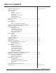
TABLE OF CONTENTS IMPORTANT SAFETY NOTICE ..................................................... TABLE OF CONTENTS INTRODUCTION General Operator Qualifications Orientation Related Manuals & Decals Models Covered Serial Number Location SAFETY HIGHLIGHTS ............................................................... DECALS ................................................................................. Decals OPERATORS CAB .....................................................................
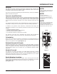
INTRODUCTION General This Manual provides important information regarding safe operating and maintenance requirements for GRADALL Material Handlers. Refer to front cover for specific model and serial number range. If you have any questions regarding the material handler, contact your GRADALL Material Handler Distributor.
SAFETY HIGHLIGHTS Read and understand all manuals and instructional material listed on cover, inside front cover and introduction page of this Manual before starting, operating or performing maintenance procedures on this equipment.
Release trapped pressure before disconnecting, opening or removing any hydraulic component. ! WARNING Keep all windows and mirror(s) clean. Adjust mirror(s) as required for maximum visibility, before and during operation. Contact The Gradall Company prior to welding on machine. Do not increase engine speed with the transmission in forward or reverse and the service brake pedal depressed in an attempt to get quicker hydraulic performance. This could cause unexpected machine movement.
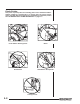
Pinch Points Stay clear of pinch points and rotating parts on the material handler. Getting caught in a pinch point or a moving part can cause serious injury or death. Before performing any maintenance on machine, follow the “STANDARD SHUT-DOWN PROCEDURE” on page 1.1. Front & Rear Steering Axles Boom Boom Holes Attachment Tilt Cylinder Carriage Forks 1.
I TH S G PA E IN TE Form No. 20127 • G9-43A Owner/Operator Manual I NT O L NA LY F LE T B N LA K.
DECAL LOCATIONS Figure 2-1 S/N 0193001 thru 0160000668 1 3 5 4 2 A STAY CLEAR OF PINCH POINT AREA ANYTIME ENGINE IS RUNNING. BEING IN PINCH POINT AREA COULD CAUSE SERIOUS INJURY OR DEATH. 1 A Genuine Parts HYDRAULIC SYSTEM FILL WITH TRACTOR HYDRAULIC FLUID R or equivalent. For Mobil Product Information, Call 1-800-662-4525. 9114-3288 9114-3282 STAY CLEAR OF PINCH POINT AREA ANYTIME ENGINE IS RUNNING. BEING IN PINCH POINT AREA COULD CAUSE SERIOUS INJURY OR DEATH.
Figure 2-2 S/N 0193001 thru 0160000668 22 D 23 24 25 D 1 21 0° 20 25 VIEW D-D 26 27 25 28 12 29 32 30 31 33 34 35 20 21 22 23 24 25 26 27 9055-3026 9114-3290 9100-3031 9147-3132 9151-3043 8060-3037 9100-3016 9100-3018 Warning Decal, Lifting Personnel Warning Decal, Attachment Boom Angle Decal JLG/Gradall Decal G9-43A Decal Warning Decal, Pinch Point “1” Decal “2” Decal Form No.
Figure 2-3 S/N 0160000683 thru Current 1 4 3 2 1 MOVING PARTS could crush causing death or serious injury. Keep clear of wheels and moving parts while engine is running. 9150-3108 REV - 9151-3198 REV - 9151-3209 REV - MOVING PARTS can cut or entangle. Keep clear while engine is running. 9150-3097 REV. - MOVING PARTS could crush causing death or serious injury. Keep clear of wheels and moving parts while engine is running.
Figure 2-4 S/N 0160000683 thru Current 18 20 19 21 MOVING PARTS could cut or crush causing death or serious injury. Keep clear of moving parts while engine is running. 9151-3210 REV - STAY CLEAR OF PINCH POINT AREA ANYTIME ENGINE IS RUNNING. BEING IN PINCH POINT AREA COULD CAUSE SERIOUS INJURY OR DEATH. 9114-3282 22 21 20 19 B 18 MOVING PARTS could cut or crush causing death or serious injury. Keep clear of moving parts while engine is running.
GENERAL NOTES DECALS R SA USE CAPACITY CHART FOR SPECIFIC ATTACHMENT ON MACHINE. MP FOR OTHER ATTACHMENTS CONSULT A GRADALL DEALER FOR LOAD RATINGS NOT LISTED. LE O USE LARGEST NUMBER VISIBLE FROM THE CAB TO DETERMINE BOOM EXTENSION. NL MATCH WITH BOOM ANGLE TO DETERMINE ALLOWABLE LOAD. FIGURES SHOWN ARE STACKING CAPACITY TRUCK LEVEL. RATED LIFTING CAPACITIES SHOWN ARE WITH MACHINE ON A FIRM, LEVEL SURFACE WITH UNDAMAGED, PROPERLY INFLATED TIRES.
LUBRICATION AND MAINTENANCE GRADALL IS A REGISTERED TRADEMARK FOR HYDRAULIC EQUIPMENT BUILT BY THE JLG COMPANY 1 JLG DRIVE, McCONNELLSBURG, PA. U.S.A. Diesel Engine Air Cleaner Element Fuel Filter Engine Oil Filter Engine Oil Coolant Diesel Fuel G9-43A SA C CAPACITY WITH STANDARD 48" & 72" CARRIAGE. CAP# X1000 SA A B C D MP 9.0 36' 24" 24" 0.8' LE 8.0 40' 24" 24" 2.3' ON SHIPPED ATTACHMENT WITH 48" CARRIAGE P/N 9140-5073 * 72" CARRIAGE P/N 9140-5074 * B 7.0 43' 24" 24" 3.6' CAP# 1000 9.
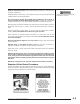
DECALS AVOID HIGH VOLTAGE LINES. IT IS UNLAWFUL TO PLACE ANY PART OF THIS MACHINE OR LOAD WITHIN 10 FEET OF HIGH VOLTAGE LINES UP TO 50,000 VOLTS. DEATH OR INJURY MAY RESULT FROM CONTACTING ELECTRIC LINES. 10 FT. (3 M) CONTACTING ELECTRIC POWER LINES will result in death o r s e r i o u s i n j u r y. Do not place machine or load within 10 feet (3m) of electric power lines. 9150-3110 REV - A 8060-3022 Located on cab fender S/N 0193001 thru 0160000668 P/N 8060-3022 NO RIDERS PERMITTED ON HANDLER.
STAY CLEAR OF MOVING PARTS WHILE ENGINE IS RUNNING. MOVING PARTS CAN CAUSE SERIOUS INJURY. 9114-3281 STAY CLEAR OF PINCH POINT AREA ANYTIME ENGINE IS RUNNING. BEING IN PINCH POINT AREA COULD CAUSE SERIOUS INJURY OR DEATH. 9114-3282 Located on both sides of frame near axles S/N 0193001 thru 0160000668 P/N 9114-3282 M O V I N G PA R T S c o u l d crush causing death o r s e r i o u s i n j u r y.
DECALS JUMP STARTING INSTRUCTIONS LEAD ACID BATTERIES PRODUCE FLAMABLE AND EXPLOSIVE GASSES WHEN CHECKING, TESTING, USING BOOSTER BATTERY OR CHARGING BATTERIES: * DO NOT USE SMOKING MATERIALS NEAR BATTERIES * KEEP FLAMES AND SPARKS AWAY FROM BATTERIES * WEAR SAFETY GLASSES * ASSURE BATTERY IS NOT FROZEN AND ELECTROLYTE IS AT PROPER LEVEL IN EACH CELL FAILURE TO FOLLOW THESE INSTRUCTIONS COULD RESULT IN SERIOUS INJURY OR DAMAGE TO THE ELECTRICAL SYSTEM 9114-3284 Located on frame below engine cover S/N 0193
Located on left side of boom P/N 9100-3031 MAXIMUM OCCUPANCY THREE (3) PEOPLE. DO NOT USE PERSONNEL WORK PLATFORM WITHOUT THE PROPER GRADALL MATERIAL HANDLER/PERSONNEL WORK PLATFORM CAPACITY CHART DISPLAYED IN CAB. FAILURE TO COMPLY COULD RESULT IN SERIOUS INJURY OR DEATH. 9055-3031 REV. A Located on Personnel Work Platform P/N 9055-3031 406 MILL AVE. S.W. NEW PHILADELPHIA, OHIO MADE IN U. S. A. ATTACHMENT READ AND UNDERSTAND THE FOLLOWING PRIOR TO LIFTING PERSONNEL.
I TH S G PA E IN TE I NT O L NA LY F LE T B N LA K.
OPERATOR’S CAB OPERATOR’S CAB The cab permits vision from all sides and includes an overhead guard to provide protection from falling objects. A fully-enclosed cab with windows and a lockable door is available as an option. The top half of the cab door must be secured in the fully-opened or closed position. The bottom half of the cab door can be secured in the closed position only. Be sure the door is fully secured when operating the handler.
OPERATOR’S CAB Accelerator Pedal: Depress pedal to increase speed and release pedal to decrease speed. Attachment Tilt Lever: This lever controls tilt of the fork carriage. Speed is proportional to lever actuation and engine RPM. Push lever forward to tilt down; pull lever back to tilt up. Attachment Tilt Switch (optional): Depress left side of switch to tilt down; depress right side of switch to tilt up. Auxiliary Control Lever (optional): This lever is used to control optional hydraulic attachments.
Machine Level Lever: This lever controls the relationship of the handler frame to the front axle. Move the lever left to tilt frame to left, move the lever right to tilt frame to right. Neutral Lock Lever: The transmission control switch is equipped with a lever that locks the transmission in neutral when activated. Parking Brake Switch: This switch controls the application and release of the parking brake. Indicator light on switch glows (red) to indicate brake is applied.
CHECKS & SERVICES BEFORE STARTING ENGINE To be performed at the beginning of each work shift. • Check to be sure the material handler is equipped with the proper load/ capacity chart and that it is legible before operating. • If spark arrestors are required, be sure they are in place and in good working order. ! WARNING Use extreme caution when checking items beyond your normal reach. Use an approved safety ladder. • Check to be certain that windows and mirror(s) are clean and undamaged.
WARM-UP & OPERATIONAL CHECKS To be performed at beginning of each work shift. The safety, efficiency and service life of your handler will be increased by performing the operational checks listed below. Items preceded by an asterisk (*) are optional and may not be furnished on your machine. Before entering the operator’s cab, check: 1. Engine oil level. 2. Air Filter Restriction Indicator. If needle is in red area, filter is clogged and element must be cleaned or changed.
ENGINE OPERATION Starting the Engine 1. Make sure all controls are in “Neutral” and all electrical components (lights, heater, defroster, etc.) are turned off. Set parking brake. 2. Depress accelerator pedal approximately 1/4 to 1/3 of travel from top. 3. Turn ignition switch to “START” to engage starting motor. Release key immediately when engine starts. If engine fails to start within 20 seconds, release key and allow starting motor to cool for a few minutes before trying again. 4.
Normal Engine Operation Observe gauges frequently to be sure all engine systems are functioning properly. The voltmeter shows the “charge/discharge” state of the battery charging system. With the engine running, meter should indicate 13.5 to 14 volts. With engine stopped, meter indicates battery charge (12 volts). Be alert for unusual noises or vibration. When an unusual condition is noticed, park machine in safe position and perform standard shut-down procedure. (See Page 1.
BRAKE SYSTEM General The brake system includes a service brake and a parking brake. Service and parking brakes are applied through wet disc brake packs located within axle housing. Service Brakes Depressing the service brake pedal causes controlled hydraulic pressure to be applied to service brakes. The greater the pedal travel, the greater the braking force. ! WARNING If power-assist feature should fail for any reason, it would require greater effort to apply service brake.
PARKING THE HANDLER Precautions • Avoid parking on slopes or near an excavation. • Park on level ground and chock wheels. • Avoid parking on roads or highways. If it cannot be avoided,be sure to display warning flags during day and flares or flashing lights at night. • Position attachment on ground; never leave machine with boom in air. • If parking on a slope cannot be avoided, position the handler at a right angle across the slope, straighten and chock all wheels. Parking procedure 1.
STEERING SYSTEM • Three modes of steering are provided as standard equipment. A three position switch on the dashboard allows the operator to select the steering mode. • 4-wheel circle steer allows for tight turns and better maneuverability in close quarters. • 4-wheel crab steering allows the machine to move sideways at an angle, and is used to position the machine. • 2-wheel front steer is used for high speed travel.
DRIVE TRAIN General This model material handler is equipped with a powershift transmission. With this type of transmission, the operator simply selects a gear, selects the direction of travel, releases brakes and depresses the accelerator pedal to move the handler. Operation Gear Selection: A four-speed transmission is used on this machines. This transmission has four forward gears and three reverse gears. Gear selection is accomplished by rotating the twist grip handle on the transmission control lever.
LEVELING THE HANDLER “Leveling” means positioning the handler so that it is level from side to side (left to right). A level indicator is located in upper right corner of front window frame to permit operator to determine whether the handler frame is level. There are four very important things to remember about handler leveling: 1. Never engage a load or lift a load more than 1.2m (four feet) above ground unless handler is level.
OPERATING PROCEDURE & TECHNIQUES Hydraulic Controls All boom and attachment movements are governed by hydraulic controls. Rapid, jerky operation of hydraulic controls will cause rapid, jerky movement of the load. Such movements can cause the load to shift or fall or may cause the machine to tip over. Feathering Feathering is a control operation technique used for smooth operation.
Rated Capacity Chart NOTE! The rated capacity chart, located on dashboard, indicates maximum load capacities for handlers equipped with GRADALL-furnished carriage/fork or other attachment combinations. These capacities apply to standard carriage/fork and other attachment combinations except as stated on the capacity chart. See page 12-3 for instructions on how to read capacity charts.
Load Center Loads shown on rated capacity chart are based on the load center being 610mm (two feet) above and 610mm (two feet) forward of surfaces of horizontal forks. The load center of a load is the center of gravity of the load. For regularlyshaped loads of the same material, such as a pallet of blocks, the center of gravity can be located by measuring the load to find its center.
How to read a Capacity Chart When reading the capacity chart you must check to be sure the correct model number is listed. (See figure 12-5) The next thing to look for is that the part number of your attachment is listed under the “Use With” section. Identify and find the amount of boom extension required, along with the angle of the boom. Trace the boom extension arc down until it intersects with the appropriate boom angle.
NOTE! Figure 12-5: Description of items on a Capacity Chart This is a sample Capacity Chart ONLY ! Do not use this chart, use the one located in your cab.
ATTACHMENTS Approved Attachments Although the carriage/fork combination is most frequently used, several other GRADALL-approved attachments are available for use with your material handler. Contact your GRADALL Material Handler Distributor or Gradall for information on approved attachments designed to solve special material handling problems. The serial number plate lists attachments approved for use with your handler. However, there may be additional approved attachments available.
Attachment Installation ! WARNING This installation procedure is designed for one-man operation. If a helper is involved, shut off the engine before proceeding to steps 4 and 5. 1. Retract Quick Switch™ (attachment tilt lever forward) to provide clearance. Check to be sure lock pin is secured in out position with retainer pin. 2. Align boom head pivot with recess in attachment. Raise boom slightly to engage boom head pivot in recess. 3. Engage Quick Switch™ (attachment tilt lever backward). 4.
Fork Positioner Capacity: Maximum load capacity for fork positioner carriage is the same as standard carriage without fork positioner. Refer to Attachment Capacity Chart. Capacity varies with boom extension and elevation positions. Controls: Figure 13-1 OPEN FORKS AUXILIARY CONTROL LEVER CLOSE FORKS The auxiliary control lever is used to adjust fork position. Pull lever back to close forks, push lever forward to open forks. Installation Procedure: 1.
Operation: • Raise or lower boom to appropriate height for loading material from stockpile. • Align handler with face of stockpile and drive slowly and smoothly into pile to load bucket. Do not corner-load bucket. • Tilt bucket up far enough to retain load and back away from pile. • Lower bucket to carry position 1.2m (4 feet) or less above ground and travel carefully to unloading point. Turn bucket down to dump load. Mast (1.8m [6'] with 1.2m [4’] or 1.
Attachment Tilt Controls: Figure 13-4 SWING LEFT The carriage tilt cylinder is used to tilt the swing forks up and down and the carriage tilt lever controls fork tilt. SWING RIGHT The auxiliary control lever is used to swing the forks to the left and right. Pull lever back to swing forks right; push lever forward to swing forks left. AUXILIARY CONTROL LEVER Installation Procedure: 1. Remove carriage/fork combination or other attachment from boom head. See page 13.1. 2.
• Tilt carriage to left or right to align forks with load and engage load. • Raise load slightly and then level carriage. • Travel with load lowered to travel position 1.2m (4 feet) or less above ground. Boom Head-Mounted Winch Capacity: The boom head-mounted winch maximum load capacity is shown on the standard carriage capacity chart. However, maximum capacity may be used only in areas where it does not exceed capacities shown on standard carriage/ fork capacity chart (located on dashboard).
Truss Boom & Truss Boom with Winch Capacity: Maximum capacity for the truss boom (with or without winch) is shown on attachment serial number plate. However, maximum lift capacity applies only to certain areas within boom extension/elevation pattern of handler/truss boom combination. A separate capacity chart must be used for handlers equipped with truss boom. Study and understand this chart before attempting to handle a load with truss boom.
• Open clamps at heel of truss boom far enough to clear load and tilt truss boom up until truss/bundle contacts heel of truss boom. • Close clamps to hold load lightly and secure clamps. • Transport load to delivery site and attach tag lines if load will be freely suspended. Swing Mast Capacity: Maximum lift capacity is shown on attachment serial number plate. However, maximum lift capacity applies only to certain areas within boom extension/ elevation pattern of handler/swing mast combination.
Personnel Work Platform The material handler operator and personnel in the platform must read and understand the separate personnel work platform manual, included with the attachment, prior to using the platform. Capacity: The Gradall personnel work platform is designed to carry a maximum of 3 occupants. The load includes personnel, materials, tools, etc. The maximum capacity of your work platform is based on specific model material handler/ work platform combination.
OBTAINING HYDRAULIC OIL SAMPLE 1. Operate unit until hydraulic oil reaches normal operating temperature. 2. Apply parking brake, lower boom to rest and shift Forward/Reverse lever to “Neutral” Observe Hydraulic Filter Bypass Indicator with engine running at full throttle. Replace filter elements if necessary. 3. Obtain a container to receive waste oil and a CLEAN container to receive oil sample.
LOADING & SECURING FOR TRANSPORT Loading & Securing Handler For Transport 1. Level the material handler prior to loading. 2. Using a spotter, load the handler with boom as low as possible to keep a low center of gravity. 3. Once loaded, apply parking brake and lower boom until boom or attachment is resting on deck. Move all controls to “Neutral”, stop engine and remove ignition key. 4. Secure machine to deck by passing chains through four tie-down lugs on front and rear of machine.
MOVING HANDLER IN EMERGENCY The following information assumes the handler cannot be moved under its own power. Before moving the handler, read all of the following information to understand options available. Then select the appropriate method. The steering system permits manual steering if engine or power assist feature fails. Remember: • Although manual steering is possible without power assist, steering will be slow and will require much greater force.
MANUAL RELEASE OF BRAKE SYSTEM Figure 16-1 AXLE MANUAL RELEASE (steps 1-3) Block wheels before performing this procedure. ! WARNING The front axle service brakes will not operate when the park brakes are manually disengaged. The rear brakes may only provide half of the machine’s normal braking capability. Always reset the brake release screws before allowing machine back in to regular service. ADJUSTMENTS AFTER MANUAL RELEASE (steps 4-6) 1.
MAINTENANCE NOMENCLATURE Figure 17-1 4 5 6 7 8 9 10 11 12 13 STAY CLEAR OF MOVING PARTS WHILE ENGINE IS RUNNING. MOVING PARTS CAN CAUSE SERIOUS INJURY. 9114-3281 14 3 2 1 15 16 19 18 25 22 23 16 17 26 27 28 24 21 29 20 30 2 34 35 1 2 3 4 5 6 7 8 9 10 11 12 FRONT AXLE TIE-DOWN LUGS SWAY CYLINDER HYDRAULIC TANK & FILTER IMPLEMENT PUMP PRIORITY VALVE BATTERY TRANSMISSION ENGINE COMPARTMENT ENGINE RADIATOR TRANSMISSION OIL COOLER Form No.
LUBRICATION & ROUTINE MAINTENANCE Figure 17-2 1 1 2 1 DF EO HF HM 5 5 1 - 2 Lubrication Symbols DIESEL FUEL ENGINE FUEL HYDRAULIC FLUID MOLY LUBE (extreme pressure) 4 2 • SYMBOLS = Lube Fitting = Other Service = Service Both Sides FAILURE TO USE GRADALL HYDRAULIC FILTER ELEMENTS COULD VOID WARRANTY 6 3 14 16 17 18 19 20 21 22 4 2 2 IMPORTANT NOTICE Be certain to check extend chain adjustment every 5 weeks or 250 hours and adjust as required.
! CAUTION Service intervals are based on machine usage of 1500 hours annually. Use of your unit may vary significantly and you must adjust service frequency for your usage to obtain maximum service life. Frequency headings in the following schedule indicate a calender limit and an operating hour limit. Perform service at whichever interval occurs first. Daily or Shift (10 hour Maximum) Lubrication & Maintenance Lube No. of Symbol Points 12.
RECOMMENDED LUBRICANTS & CAPACITIES ! CAUTION When replacing foam filled tires, replace the complete tire and rim assembly. APPLICATION SYMBOL WHEN USED GRADE SPECIFICATION CL (chain lube) All Year - P/N 1440-4751 - - HM (extreme pres. lube) All Year NLGI #2 P/N 1440-4818 - - Coolant Additive (refer to engine man.) (SCA supplemental coolant additive) All Year - - 0.5 qts 0.48 L Transfer Case HF (hydraulic fluid) All Year ** ** 0.8 qts 0.
BOOM Checking & Adjusting Boom Boom Bearing Pads Boom bearing pads are to be adjusted for all boom sections. This should be done at boom assembly, however, some adjustments may be required after assembly. • Add shims as required so that front and sides of boom have no more than 1.5mm (.06 inch) clearance. • Add shims as required so that rear of boom has no more than 3.04mm (.12 inch) total clearance.
INSPECTION AND MAINTENANCE LOG Date 18.
HAND SIGNALS Standard Signals - When handler work conditions require hand signals, they shall be provided or posted conspicuously for the use of both signalman and operator. No handler motions shall be made unless signals are clearly understood by both signalman and operator. Special Signals - When signals for auxiliary equipment functions or conditions not covered are required, they shall be agreed upon in advance by the operator and signalman.
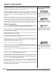
CALIFORNIA Proposition 65 Warning Diesel engine exhaust and some of its constituents are known to the State of California to cause cancer, birth defects and other reproductive harm. CALIFORNIA Proposition 65 Warning Battery posts, terminals and related accessories contain lead and lead compounds, chemicals known to the State of California to cause cancer and birth defects or other reproductive harm. Wash hands after handling. Hydraulic Equipment 406 Mill Ave.