Operation and Safety Manual Original Instructions - Keep this manual with the machine at all times.
FOREWORD FOREWORD This manual is a very important tool! Keep it with the machine at all times. The purpose of this manual is to provide owners, users, operators, lessors, and lessees with the precautions and operating procedures essential for the safe and proper machine operation for its intended purpose. Due to continuous product improvements, JLG Industries, Inc. reserves the right to make specification changes without prior notification. Contact JLG Industries, Inc. for updated information.
FOREWORD SAFETY ALERT SYMBOLS AND SAFETY SIGNAL WORDS This is the Safety Alert Symbol. It is used to alert you to the potential personal injury hazards. Obey all safety messages that follow this symbol to avoid possible injury or death INDICATES AN IMMINENTLY HAZARDOUS SITUATION. IF NOT AVOIDED, WILL RESULT IN SERIOUS INJURY OR DEATH. THIS DECAL WILL HAVE A RED BACKGROUND. INDICATES A POTENTIALLY HAZARDOUS SITUATION. IF NOT AVOIDED, MAY RESULT IN MINOR OR MODERATE INJURY.
FOREWORD For: THIS PRODUCT MUST COMPLY WITH ALL SAFETY RELATED BULLETINS. CONTACT JLG INDUSTRIES, INC. OR THE LOCAL AUTHORIZED JLG REPRESENTATIVE FOR INFORMATION REGARDING SAFETY-RELATED BULLETINS WHICH MAY HAVE BEEN ISSUED FOR THIS PRODUCT. • Accident Reporting • Product Safety Publications • Current Owner Updates JLG INDUSTRIES, INC. SENDS SAFETY RELATED BULLETINS TO THE OWNER OF RECORD OF THIS MACHINE. CONTACT JLG INDUSTRIES, INC. TO ENSURE THAT THE CURRENT OWNER RECORDS ARE UPDATED AND ACCURATE.
FOREWORD REVISION LOG Original Issue d - June 3, 2014 – JLG Lift – 3121644
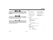
TABLE OF CONTENTS SECTION - PARAGRAPH, SUBJECT PAGE SECTION - PARAGRAPH, SUBJECT SECTION - 1 - SAFETY PRECAUTIONS 1.1 1.2 1.3 1.4 1.5 GENERAL . . . . . . . . . . . . . . . . . . . . . . . . . . . . . . . . . . . . . . . . . . . . 1-1 PRE-OPERATION . . . . . . . . . . . . . . . . . . . . . . . . . . . . . . . . . . . . . 1-1 Operator Training and Knowledge . . . . . . . . . . . . . . . . . 1-1 Workplace Inspection. . . . . . . . . . . . . . . . . . . . . . . . . . . . . . 1-2 Machine Inspection. . . .
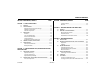
TABLE OF CONTENTS SECTION - PARAGRAPH, SUBJECT 4.7 4.8 4.9 4.10 4.11 4.12 4.13 PAGE Platform Level Adjustment . . . . . . . . . . . . . . . . . . . . . . . . 4-9 Platform Rotation . . . . . . . . . . . . . . . . . . . . . . . . . . . . . . . . . 4-9 Jib Swing. . . . . . . . . . . . . . . . . . . . . . . . . . . . . . . . . . . . . . . . . . 4-9 BOOM . . . . . . . . . . . . . . . . . . . . . . . . . . . . . . . . . . . . . . . . . . . . . . 4-10 Swinging the Boom . . . . . . . . . . . . . . . . . . . .
TABLE OF CONTENTS SECTION - PARAGRAPH, SUBJECT 6.6 PAGE SECTION - PARAGRAPH, SUBJECT Wheel Installation . . . . . . . . . . . . . . . . . . . . . . . . . . . . . . . 6-19 SUPPLEMENTAL INFORMATION . . . . . . . . . . . . . . . . . . . . . 6-20 SECTION - 7 - INSPECTION AND REPAIR LOG LIST OF FIGURES 2-1. 2-2. 2-3. 2-4. 3-1. 3-2. 3-3. 4-1. 4-2. 4-3. 4-4. 4-5. 4-6. 4-7. 6-1. 6-2. 6-3. 3121644 Basic Nomenclature. . . . . . . . . . . . . . . . . . . . . . . . . . . . . . . . . .
TABLE OF CONTENTS SECTION - PARAGRAPH, SUBJECT PAGE SECTION - PARAGRAPH, SUBJECT PAGE This page intentionally left blank.
SECTION 1 - SAFETY PRECAUTIONS SECTION 1. SAFETY PRECAUTIONS 1.1 GENERAL This section outlines the necessary precautions for proper and safe machine usage and maintenance. It is mandatory that a daily routine is established based on the content of this manual to promote proper machine usage.
SECTION 1 - SAFETY PRECAUTIONS • An operator must not accept operating responsibilities until adequate training has been given by competent and authorized persons. • Allow only those authorized and qualified personnel to operate the machine who have demonstrated that they understand the safe and proper operation and maintenance of the unit. • Precautions to avoid all hazards in the work area must be taken by the user before and during operation of the machine.
SECTION 1 - SAFETY PRECAUTIONS Machine Inspection 1.3 • Do not operate this machine until the inspections and functional checks as specified in Section 2 of this manual have been performed. General • Do not operate this machine until it has been serviced and maintained according to the maintenance and inspection requirements as specified in the machine’s Service and Maintenance Manual. • Ensure all safety devices are operating properly. Modification of these devices is a safety violation.
SECTION 1 - SAFETY PRECAUTIONS • Do not carry materials directly on platform railing unless approved by JLG. • When two or more persons are in the platform, the operator shall be responsible for all machine operations. • Always ensure that power tools are properly stowed and never left hanging by their cord from the platform work area. Trip and Fall Hazards • During operation, occupants in the platform must wear a full body harness with a lanyard attached to an authorized lanyard anchorage point.
SECTION 1 - SAFETY PRECAUTIONS • Before operating the machine, make sure all gates are closed and fastened in their proper position. Electrocution Hazards • This machine is not insulated and does not provide protection from contact or proximity to electrical current. • Keep both feet firmly positioned on the platform floor at all times. Never position ladders, boxes, steps, planks, or similar items on unit to provide additional reach for any purpose.
SECTION 1 - SAFETY PRECAUTIONS Table 1-1. Minimum Approach Distances (M.A.D.) • Allow for machine movement and electrical line swaying.
SECTION 1 - SAFETY PRECAUTIONS • The minimum approach distance may be reduced if insulating barriers are installed to prevent contact, and the barriers are rated for the voltage of the line being guarded. These barriers shall not be part of (or attached to) the machine. The minimum approach distance shall be reduced to a distance within the designed working dimensions of the insulating barrier.
SECTION 1 - SAFETY PRECAUTIONS • Never exceed the maximum work load as specified on the platform. Keep all loads within the confines of the platform, unless authorized by JLG. • Do not operate the machine when wind conditions exceed 28 mph (12.5 m/s). Refer to Table 1-2, Beaufort Scale (For Reference Only). • Keep the chassis of the machine a minimum of 2 ft. (0.6m) from holes, bumps, drop-offs, obstructions, debris, concealed holes, and other potential hazards at the ground level.
SECTION 1 - SAFETY PRECAUTIONS DO NOT OPERATE THE MACHINE WHEN WIND CONDITIONS EXCEED 28 MPH (12.5 M/ S). Table 1-2. Beaufort Scale (For Reference Only) 3121644 Wind Speed Beaufort Number mph m/s 0 0 0-0.2 Calm Calm. Smoke rises vertically 1 1-3 0.3-1.5 Light air Wind motion visible in smoke 2 4-7 1.6-3.3 Light breeze Wind felt on exposed skin. Leaves rustle Description Land Conditions 3 8-12 3.4-5.4 Gentle breeze Leaves and smaller twigs in constant motion 4 13-18 5.5-7.
SECTION 1 - SAFETY PRECAUTIONS • Keep non-operating personnel at least 6 ft. (1.8m) away from machine during all driving and swing operations. Crushing and Collision Hazards • Approved head gear must be worn by all operating and ground personnel. • Check work area for clearances overhead, on sides, and bottom of platform when lifting or lowering platform, and driving.
SECTION 1 - SAFETY PRECAUTIONS 1.4 TOWING, LIFTING, AND HAULING 1.5 • Never allow personnel in platform while towing, lifting, or hauling. This sub-section contains general safety precautions which must be observed during maintenance of this machine. Additional precautions to be observed during machine maintenance are inserted at the appropriate points in this manual and in the Service and Maintenance Manual.
SECTION 1 - SAFETY PRECAUTIONS • DO NOT use your hand to check for leaks. Use a piece of cardboard or paper to search for leaks. Wear gloves to help protect hands from spraying fluid. • Do not use machine as a ground for welding. • When performing welding or metal cutting operations, precautions must be taken to protect the chassis from direct exposure to weld and metal cutting spatter. • Do not refuel the machine with the engine running. • Use only approved non-flammable cleaning solvents.
SECTION 1 - SAFETY PRECAUTIONS Battery Hazards • Always disconnect batteries when servicing electrical components or when performing welding on the machine. • Do not allow smoking, open flame, or sparks near battery during charging or servicing. BATTERY FLUID IS HIGHLY CORROSIVE. AVOID CONTACT WITH SKIN AND CLOTHING AT ALL TIMES. IMMEDIATELY RINSE ANY CONTACTED AREA WITH CLEAN WATER AND SEEK MEDICAL ATTENTION. • Do not contact tools or other metal objects across the battery terminals.
SECTION 1 - SAFETY PRECAUTIONS NOTES: 1-14 – JLG Lift – 3121644
SECTION 2 - USER RESPONSIBILITIES, MACHINE PREPARATION, AND INSPECTION SECTION 2. USER RESPONSIBILITIES, MACHINE PREPARATION, AND INSPECTION 6. The safest means to operate the machine where overhead obstructions, other moving equipment, and obstacles, depressions, holes, drop-offs. 2.1 PERSONNEL TRAINING The aerial platform is a personnel handling device; so it is necessary that it be operated and maintained only by trained personnel.
SECTION 2 - USER RESPONSIBILITIES, MACHINE PREPARATION, AND INSPECTION 2.2 PREPARATION, INSPECTION, AND MAINTENANCE The following table covers the periodic machine inspections and maintenance recommended by JLG Industries, Inc. Consult local regulations for further requirements for aerial work platforms.
SECTION 2 - USER RESPONSIBILITIES, MACHINE PREPARATION, AND INSPECTION Table 2-1.Inspection and Maintenance Table Type Pre-Start Inspection Primary Responsibility Frequency Reference User or Operator User or Operator Operator and Safety Manual Pre-Delivery Inspection (See Note) Before each sale, lease, or rental delivery.
SECTION 2 - USER RESPONSIBILITIES, MACHINE PREPARATION, AND INSPECTION 5. “Walk-Around” Inspection – Refer to Figure 2-2. thru Figure 2-4. Pre-Start Inspection The Pre-Start Inspection should include each of the following: 6. Battery – Charge as required. 1. Cleanliness – Check all surfaces for leakage (oil, fuel, or battery fluid) or foreign objects. Report any leakage to the proper maintenance personnel. 7. Fuel (Combustion Engine Powered Machines) – Add the proper fuel as necessary. 2.
SECTION 2 - USER RESPONSIBILITIES, MACHINE PREPARATION, AND INSPECTION 2. Raise, extend, retract, and lower the Upper Boom. Check for smooth operation. Function Check A functional check of all systems should be performed, once the walk-around inspection is complete, in an area free of overhead and ground level obstructions. First, using the ground controls, check all functions controlled by the ground controls. Next, using the platform controls, check all functions controlled by the platform controls. 3.
SECTION 2 - USER RESPONSIBILITIES, MACHINE PREPARATION, AND INSPECTION DO NOT DRIVE ON GRADES WHICH EXCEED THE RATED GRADEABILITY OF THE MACHINE AS INDICATED ON THE SERIAL NUMBER PLATE. DO NOT DRIVE ON SIDESLOPES WHICH EXCEED 5 DEGREES. 7. Check that platform self-leveling system functions properly during raising and lowering of boom. 8. Check rotator for smooth operation and assure platform will rotate 75 degrees in both directions from centerline of boom.
SECTION 2 - USER RESPONSIBILITIES, MACHINE PREPARATION, AND INSPECTION 1. Platform Control Console 2. Platform 3. Upper Boom 4. Telescope Cylinder (inside) 5. Master Cylinder 6. Upper Upright 7. Upper Lift Cylinder 8. Mid Lift Cylinder 9. Lower Boom 10. Turntable 11. Frame 12. Steer Wheels 13. Drive Wheels 14. Battery Box 15. Lower Lift Cylinder 16. Lower Link 17. Lower Upright 18. Upper Link 19. Mid Boom 20. Slave Cylinder 21. Footswitch Figure 2-1.
SECTION 2 - USER RESPONSIBILITIES, MACHINE PREPARATION, AND INSPECTION Figure 2-2.
SECTION 2 - USER RESPONSIBILITIES, MACHINE PREPARATION, AND INSPECTION General Begin the “Walk-Around Inspection” at Item 1, as noted on the diagram. Continue to the right (counterclockwise viewed from top) checking each item in sequence for the conditions listed in the “Walk-Around Inspection Checklist”. 1. Platform and Gate Assembly - Platform mounting pins secure. Footswitch in good working order; not modified, disabled or blocked; Bar slides freely. 2.
SECTION 2 - USER RESPONSIBILITIES, MACHINE PREPARATION, AND INSPECTION 9. Drive Axle and Motor - See Note. 16. Battery Charger - See Note. 10. Wheel/Tire Assembly - No loose or missing lug nuts. Inspect for worn tread, cuts, tears or other discrepancies. Inspect wheels for damage and corrosion. 11. Swing Motor and Worm Gear - See Note. 12. Hydraulic Pump and Reservoir - Properly secured; no visible damage or hydraulic leaks.
SECTION 3 - MACHINE CONTROLS AND INDICATORS SECTION 3. MACHINE CONTROLS AND INDICATORS 3.1 NOTE: GENERAL THE MANUFACTURER HAS NO DIRECT CONTROL OVER MACHINE APPLICATION AND OPERATION. THE USER AND OPERATOR ARE RESPONSIBLE FOR CONFORMING WITH GOOD SAFETY PRACTICES. This section provides the necessary information needed to understand control functions. 3.2 CONTROLS AND INDICATORS NOTE: 3121644 This machines is equipped with control panels that use symbols to indicate control functions.
SECTION 3 - MACHINE CONTROLS AND INDICATORS 2. Platform Overload (If equipped) Ground Control Station Indicates the platform has been overloaded. (See Figure 3-1.) NOTE: When machine is shut down the Platform/Ground Select switch and Emergency Stop must be positioned to Off. NOTE: The Function Enable switch must be held down in order to operate Telescope, Lower Lift, Swing, Main Lift, Jib Lift, Platform Level Override, and Platform Rotate functions. 3.
SECTION 3 - MACHINE CONTROLS AND INDICATORS 1. 2. 3. 4. 5. 6. 7. 8. 9. 10. 11. 12. 13. 14. 15. System Distress Indicator Platform Overload Indicator Engine/Generator Start Button Battery Condition Indicator & Hourmeter Telescope Swing Function Enable Circuit Breakers Emergency Stop Platform/Ground Select Lower/Mid Lift Upper Boom Lift Jib Platform Leveling Rotate Figure 3-1.
SECTION 3 - MACHINE CONTROLS AND INDICATORS 5. Telescope 9. Power/Emergency Stop Switch Provides for extension and retraction of Upper Boom when positioned to in or out. A two-position red mushroom shaped switch furnishes power to Platform/Ground Select switch when pulled out (on). When pushed in (off ), power is shut off to the Platform/Ground Select switch. 6. Swing 10. Platform/Ground Select Switch The Swing control switch provides 360 degrees non-continuous turntable rotation.
SECTION 3 - MACHINE CONTROLS AND INDICATORS 11. Lower/Mid Boom Lift Provides for raising and lowering of Lower Boom when positioned to Up or Down. ONLY USE THE PLATFORM LEVELING OVERRIDE FUNCTION FOR SLIGHT LEVELING OF THE PLATFORM. INCORRECT USE COULD CAUSE THE LOAD/OCCUPANT TO SHIFT OR FALL. FAILURE TO DO SO COULD RESULT IN DEATH OR SERIOUS INJURY. 14. Platform Leveling Override 12. Upper Boom Lift A three position switch allows the operator to adjust the automatic self leveling system.
SECTION 3 - MACHINE CONTROLS AND INDICATORS 3. Horn Platform Station A push-type Horn switch supplies electrical power to an audible warning device when pressed. (See Figure 3-3.) 1. Posi-Track Control 4. Power/Emergency Stop Activating the Posi-Track switch allows the operator to engage positive traction for the time period pre-set in the controller.
SECTION 3 - MACHINE CONTROLS AND INDICATORS 1. 2. 3. 4. Posi-Track Platform Leveling Override Horn Power/Emergency Stop 5. 6. 7. 8. Generator Enable Drive Orientation Override Drive/Steer Telescope 9. 10. 11. 12. Lights Jib Soft Touch Override Jib Swing 13. 14. 15. 16. Lower Boom Lift Platform Rotate Function Speed Main Lift/Swing Figure 3-2.
SECTION 3 - MACHINE CONTROLS AND INDICATORS 5. Generator Enable Control The Generator Enable control switch, when in the off position, allows the operator to prevent the generator engine from starting when using the machine indoors. When in the on position (and the ground Emergency Stop Switch on [pulled out]), the generator is enabled to automatically start when the batteries need charged. NOTE: To operate the Drive joystick, pull up on the locking ring below the handle.
SECTION 3 - MACHINE CONTROLS AND INDICATORS 11. Soft Touch Override Switch (If equipped) TO AVOID SERIOUS INJURY, DO NOT OPERATE MACHINE IF ANY CONTROL LEVERS OR TOGGLE SWITCHES CONTROLLING PLATFORM MOVEMENT DO NOT RETURN TO THE OFF OR NEUTRAL POSITION WHEN RELEASED. 8. Telescope Control This switch enables the functions that were cut out by the Soft Touch system to operate again at creep speed, allowing the operator to move the platform away from the obstacle that caused the shutdown situation. 12.
SECTION 3 - MACHINE CONTROLS AND INDICATORS 14. Platform Rotate The PLATFORM ROTATE control switch allows the operator to rotate the basket to the left or right when positioned to the desired direction. NOTE: 16. Main Lift/Swing Controller Provides main lift and swing. Push forward to lift up, pull backward to boom down. Move right to swing right, move left to swing left. Moving the joystick activates switches to provide the functions selected. 15.
SECTION 3 - MACHINE CONTROLS AND INDICATORS Table 3-1.
SECTION 3 - MACHINE CONTROLS AND INDICATORS 2. Platform Overload (If equipped) Platform Control Indicator Panel (See Figure 3-3., Platform Control Indicator Panel w/Drive Orientation) Indicates the platform has been overloaded. 1. Tilt Alarm Warning Light and Alarm This illuminator indicates that the chassis is on a slope. An alarm will also sound when the chassis is on a slope and the boom is above horizontal.
SECTION 3 - MACHINE CONTROLS AND INDICATORS 1. 2. 3. Tilt Platform Overload System Distress 4. 5. 6. Posi-Track Enable Low Battery 7. 8. 9. Creep Drive Orientation Override Soft Touch Indicator Figure 3-3.
SECTION 3 - MACHINE CONTROLS AND INDICATORS 3. System Distress Indicator d. There is some other fault in one of the circuits. If so determine the cause by counting the flash code, a number of flashes followed by a pause followed by another number of flashes, and refer to the service manual. The system distress indicator lights to signify an abnormal condition for the generator engine (high oil temperature or low oil pressure) or, on all electric machines, an electrical system fault.
SECTION 3 - MACHINE CONTROLS AND INDICATORS 5. Posi-Track Indicator This indicator lights to show that positraction is operating. TO AVOID SERIOUS INJURY, DO NOT REMOVE, MODIFY OR DISABLE THE FOOTSWITCH BY BLOCKING OR ANY OTHER MEANS. FOOTSWITCH MUST BE ADJUSTED IF FUNCTIONS ACTIVATE WHEN SWITCH ONLY OPERATES WITHIN LAST 1/4" OF TRAVEL, TOP OR BOTTOM. 6. Enable Indicator/Footswitch 7.
SECTION 3 - MACHINE CONTROLS AND INDICATORS 8. Soft Touch Indicator (If Equipped) 9. Creep Speed Indicator When illuminated (Yellow) the Soft Touch bumper is against an object. All controls are disabled until the override button is pushed, at which time controls are active in the Creep mode. 3-16 When the Function Speed Control is turned to the creep position, the indicator acts as a reminder that all functions are set to the slowest speed.
SECTION 4 - MACHINE OPERATION SECTION 4. MACHINE OPERATION 4.1 DESCRIPTION 4.2 This machine is a self-propelled hydraulic personnel lift equipped with a work platform on the end of an elevating and rotating boom. Capacities The primary operator control station is in the platform. From this control station, the operator can drive and steer the machine in both forward and reverse directions. The operator can raise or lower the upper or lower boom or swing the boom to the left or right.
SECTION 4 - MACHINE OPERATION Stability 4.3 Machine stability is based on two positions which are called Forward and Backward stability. The machines position of least Forward stability is shown in Figure 4-1., Position of Least Forward Stability, and its position of least Backward stability is shown in Figure 4-2., Position of Least Backward Stability. TO AVOID FORWARD OR BACKWARD TIPPING, DO NOT OVERLOAD MACHINE OR OPERATE THE MACHINE ON AN OUT-OF-LEVEL SURFACE.
SECTION 4 - MACHINE OPERATION UPPER BOOM HORIZONTAL FLY BOOM FULLY EXTENDED MACHINE WILL "TIP OVER" IN THIS DIRECTION IF OPERATED ON AN OUT-OF-LEVEL SURFACE TOWER AND MID BOOM AT 33 DEGREES Figure 4-1.
4-4 – JLG Lift – LOWER BOOM FULLY ELEVATED MID BOOM FULLY ELEVATED UPPER BOOM FULLY ELEVATED AND RETRACTED Figure 4-2.
SECTION 4 - MACHINE OPERATION Platform/Ground Select Switch 4.4 The Platform/Ground Select switch directs battery power to the desired control station when the Power/Emergency Stop switch is pulled out (on). With the switch held in the Ground position battery power is supplied to the ground control station. When the switch is in the Platform position, battery power is supplied to the platform control station.
SECTION 4 - MACHINE OPERATION USE EXTREME CAUTION WHEN DRIVING IN REVERSE AND AT ALL TIMES WHEN DRIVING WITH PLATFORM ELEVATED AND WHEN DRIVING WITH ANY PART OF MACHINE WITHIN 6 FEET OF ANY OBSTRUCTION. BEFORE DRIVING, LOCATE THE BLACK/WHITE ORIENTATION ARROWS ON BOTH THE CHASSIS AND THE PLATFORM CONTROLS. MOVE THE DRIVE CONTROLS IN A DIRECTION MATCHING THE DIRECTIONAL ARROWS FOR THE INTENDED DIRECTION OF TRAVEL.
SECTION 4 - MACHINE OPERATION Figure 4-3.
SECTION 4 - MACHINE OPERATION 1. Match the black and white direction arrows on both platform control panel and the chassis to determine the direction the machine will travel. 2. Push and release the Drive Orientation Override switch. Within 3 seconds, slowly move the Drive control toward the arrow matching the intended direction of machine travel. The indicator light will flash during the 3 second interval until the drive function is selected. 4.5 4.6 PLATFORM Loading From Ground Level 1.
SECTION 4 - MACHINE OPERATION Platform Level Adjustment Jib Swing 1. Depress footswitch. To raise platform, position Platform/Level control switch Up and hold until platform is level. 1. Depress footswitch. To rotate Jib and platform to the left, Jib Swing control switch is positioned to the Left and held until desired position is reached. 2. Depress footswitch. To lower platform, position Platform/Level control switch to Down and hold until platform is level.
SECTION 4 - MACHINE OPERATION 4.7 BOOM Swinging the Boom To swing boom, with footswitch activated, position Swing control switch to Right or Left for direction desired. A RED TILT WARNING LIGHT IS LOCATED ON THE CONTROL CONSOLE WHICH LIGHTS WHEN THE CHASSIS IS ON A 5 DEGREE OR GREATER SLOPE. DO NOT SWING OR RAISE BOOM ABOVE HORIZONTAL WHEN LIGHT IS LIT OR AUDIBLE ALARM SOUNDS. DO NOT DEPEND ON TILT ALARM AS A LEVEL INDICATOR FOR THE CHASSIS.
SECTION 4 - MACHINE OPERATION 4.8 GENERATOR Battery Only Operating Mode The machine is equipped with an engine powered DC generator connected in parallel to the 48V DC battery bank. The machine will operate in the battery only mode when the following two conditions apply: 1. Ground Control Emergency Stop Switch is pulled out (on), and: Automatic Operating Mode The generator will operate in automatic mode always when the following two conditions apply. 1.
SECTION 4 - MACHINE OPERATION Manual (Charge) Operating Mode 4.9 INVERTER The generator will operate in manual mode always when the following three conditions apply. The inverter converts 48 VDC to 110 VAC to allow operation of power tools from the machine’s batteries. 1. Ground Control Emergency Stop Switch is pulled out (on), and: • The inverter is operational when the emergency stop switch is pulled out. • The machine and inverter can be operated at the same time.
SECTION 4 - MACHINE OPERATION 4.11 BOOM SYNCHRONIZING PROCEDURE 4.12 SHUT DOWN AND PARK NOTE: NOTE: When parking battery powered units overnight, batteries should be charged in accordance with instructions in Section 2 to ensure readiness for following workday. NOTE: Electric machines are equipped with a static strap due to static electricity build-ups. Strap is located under rear of machine chassis. If the Lower Boom assembly does not fully lower: 1. Remove all personnel from the platform. 2.
SECTION 4 - MACHINE OPERATION 4.13 MACHINE LIFTING AND TIE DOWN Tie Down See Figure 4-4. 1. Place the boom in the stowed position. 2. Remove all loose items from the machine. Lifting 1. Refer to the Serial Number Plate, refer to the Specifications section of this manual, or weigh the individual unit to find out the Gross Vehicle Weight. 3. Secure the chassis and the platform using straps or chains of adequate strength. 2. Place the boom in the stowed position. 3.
SECTION 4 - MACHINE OPERATION Figure 4-4.
SECTION 4 - MACHINE OPERATION Figure 4-5.
SECTION 4 - MACHINE OPERATION Figure 4-6.
SECTION 4 - MACHINE OPERATION Figure 4-7.
SECTION 4 - MACHINE OPERATION Table 4-1. E400A/E400AJP Decal Legend 3121644 Item # ANSI 0259301-B CE/AusI 0275070-7 Japanese 0259536-B Korean 0259538-14 Eng/ Lat.
SECTION 4 - MACHINE OPERATION Table 4-1. E400A/E400AJP Decal Legend 4-20 Item # ANSI 0259301-B CE/AusI 0275070-7 Japanese 0259536-B Korean 0259538-14 Eng/ Lat.
SECTION 4 - MACHINE OPERATION Table 4-1. E400A/E400AJP Decal Legend 3121644 Item # ANSI 0259301-B CE/AusI 0275070-7 Japanese 0259536-B Korean 0259538-14 Eng/ Lat.
SECTION 4 - MACHINE OPERATION Table 4-1. E400A/E400AJP Decal Legend 4-22 Item # ANSI 0259301-B CE/AusI 0275070-7 Japanese 0259536-B Korean 0259538-14 Eng/ Lat.
SECTION 4 - MACHINE OPERATION Table 4-1. E400A/E400AJP Decal Legend 3121644 Item # ANSI 0259301-B CE/AusI 0275070-7 Japanese 0259536-B Korean 0259538-14 Eng/ Lat.
SECTION 4 - MACHINE OPERATION Table 4-1. E400A/E400AJP Decal Legend 4-24 Item # ANSI 0259301-B CE/AusI 0275070-7 Japanese 0259536-B Korean 0259538-14 Eng/ Lat.
SECTION 4 - MACHINE OPERATION Table 4-2.
SECTION 4 - MACHINE OPERATION Table 4-2.
SECTION 4 - MACHINE OPERATION Table 4-2.
SECTION 4 - MACHINE OPERATION Table 4-2.
SECTION 4 - MACHINE OPERATION Table 4-2.
SECTION 4 - MACHINE OPERATION NOTES: 4-30 – JLG Lift – 3121644
SECTION 5 - EMERGENCY PROCEDURES SECTION 5. EMERGENCY PROCEDURES 5.1 GENERAL This section explains the steps to be taken in case of an emergency situation while operating. 5.2 INCIDENT NOTIFICATION JLG Industries, Inc. must be notified immediately of any incident involving a JLG product. Even if no injury or property damage is evident, the factory should be contacted by telephone and provided with all necessary details.
SECTION 5 - EMERGENCY PROCEDURES Platform or Boom Caught Overhead 5.5 If the platform or boom becomes jammed or snagged in overhead structures or equipment, rescue platform occupants prior to freeing the machine. 5.4 The manual descent system is used, in the event of total power failure, to lower the upper and lower booms using gravity. To operate the manual descent system, proceed as follows: EMERGENCY TOWING PROCEDURES 1. Locate manual descent knob on main valve and turn clockwise.
SECTION 6 - GENERAL SPECIFICATIONS & OPERATOR MAINTENANCE SECTION 6. GENERAL SPECIFICATIONS & OPERATOR MAINTENANCE 6.1 INTRODUCTION 6.2 This section of the manual provides additional necessary information to the operator for proper operation and maintenance of this machine.
SECTION 6 - GENERAL SPECIFICATIONS & OPERATOR MAINTENANCE Table 6-1. Operating Specifications Table 6-1. Operating Specifications Turning Radius (Inside) E/M400AJP E400An; E/M400AJPn Maximum Tire Load: E 400Anarrow E/M400AJP E/M400AJPnarrow Ground Bearing Pressure E 400Anarrow E/M400AJP E/M400AJPnarrow Drive Speed: (Above Horz.) E/M400AJP E400An; E/M400AJPn Gross Machine Weight E400An E400AJP M400AJP E400AJPn M400AJPn Maximum System Voltage 6-2 2 ft.-0 in. (0.61 m.) 2 ft.- 10 in. (0.86 m.) 4700 lbs.
SECTION 6 - GENERAL SPECIFICATIONS & OPERATOR MAINTENANCE Capacities Tires Table 6-2. Capacities Generator Fuel Tank Table 6-3. Tire Specifications 4 Gallons (15.1 L) Size Type Pressure Ply Rating Load Range Hydraulic Oil Tank E400An E/M400AJP, E/M400AJPn 4 gallons. (15.1L) 5 Gallons (19 L) w/ 10% air space IN240/55-17.5 Pneumatic 90 psi (6 Bar) 10 E IN240/55-17.5 Foam-Filled N/A 10 E Hydraulic System (Including Tank) 9 Gallons (34.1 L) LT215/8R16 Torque Hub, Drive* 17 ounces (0.
SECTION 6 - GENERAL SPECIFICATIONS & OPERATOR MAINTENANCE Table 6-4. Dimensional Data Dimensional Data Table 6-4. Dimensional Data Machine Length (stowed) E400An E/M400AJP; E/M400AJPn 18 ft. 1 in. (5.50 m) 22.0 ft. (6.7 m) Machine Height (stowed) E/M400AJP E400An; E/M400AJPn 6 ft. 7 in. (2.0 m) 6 ft. 5.75 in. (1.31m) Up and Over Platform Height 21 ft. 5 in. (6.55 m) Horizontal Reach @ Maximum Up and Over E 400An E/M400AJP, E/M400AJPn 6-4 Track Width E/M400AJP E400An; E/M400AJPn 5 ft. 0 in. (1.
SECTION 6 - GENERAL SPECIFICATIONS & OPERATOR MAINTENANCE Table 6-7. Mobil DTE 11M Specs Hydraulic Oil Table 6-6. Hydraulic Oil Hydraulic System Operating Temperature Range S.A.E. Viscosity Grade +0o to + 180o F(-18o to +83o C 10W +0o to + 210o F(-18o to +99o C 10W-20, 10W30 +50o to + 210o F(+10o to +99o C NOTE: ISO Viscosity Grade #15 Gravity API 31.9 Pour Point, Max -40°F (-40°C) Flash Point, Min.
SECTION 6 - GENERAL SPECIFICATIONS & OPERATOR MAINTENANCE Table 6-8. Mobil EAL H Series Specs Type Synthetic Biodegradable ISO Viscosity Grade 32 Specific Gravity .950 Pour Point -59°F (-51°C) Flash Point 514°F (268°C) Weight 7.64 lb. per gal. (0.9 kg per liter) Critical Stability Weights Table 6-9. Critical Stability Weights Component KG. LB. 1746 3850 Tire & Wheel (foam-filled) 94 207 Platform (4ft [1.2 m]) 41 90 Platform (5 ft. [1.
SECTION 6 - GENERAL SPECIFICATIONS & OPERATOR MAINTENANCE the end of the upper boom, mid boom, and lower boom at the left rear of the booms. Serial Number Locations For machine identification, a serial number plate is affixed to the left rear of frame, in front of left rear wheel. If the serial number plate is damaged or missing, the machine serial number is stamped on the top left side of the frame and the top left side of the turntable.
Figure 6-2.
Figure 6-3.
SECTION 6 - GENERAL SPECIFICATIONS & OPERATOR MAINTENANCE 6.3 MAINTENANCE AND LUBRICATION NOTE: The following numbers correspond to those in Figure 6-2., E400 Maintenance & Lubrication Diagram. Table 6-10. Lubrication Specifications. KEY SPECIFICATIONS MPG Multipurpose Grease having a minimum dripping point of 350 degrees F. Excellent water resistance and adhesive qualities; and being of extreme pressure type (Timken OK 40 pounds minimum).
SECTION 6 - GENERAL SPECIFICATIONS & OPERATOR MAINTENANCE 2. Swing Bearing/Worm Gear Teeth DO NOT OVERGREASE BEARINGS. OVERGREASING BEARINGS WILL RESULT IN BLOWING OUTER SEAL IN HOUSING. Lube Point(s) - Grease Fittings Capacity - Spray On Lube - OG or Mobiltac375NC Interval - A/R Comments - If necessary install grease fittings into worm gear housing and grease bearings. NOTE: 3121644 OG will allow better cycle times than Mobiltac375NC, however Mobiltac375NC must be used in dusty environments.
SECTION 6 - GENERAL SPECIFICATIONS & OPERATOR MAINTENANCE 3. Hydraulic Tank Lube Point(s) - Fill Cap Capacity - 4 Gal. (15.1 L) Lube - HO Interval - Check Level daily; Change every 2 years or 1200 hours of operation. Comments - On new machines, those recently overhauled, or after changing hydraulic oil, operate all systems a minimum of two complete cycles and recheck oil level in reservoir.
SECTION 6 - GENERAL SPECIFICATIONS & OPERATOR MAINTENANCE 4. Hydraulic Return Filter E400 Interval - Change after first 50 hrs. and every 6 months or 300 hrs. thereafter. Comments - Under certain conditions, it may be necessary to replace the hydraulic filter on a more frequent basis. A common symptom of a dirty filter is sluggishness experienced in hydraulic functions.
SECTION 6 - GENERAL SPECIFICATIONS & OPERATOR MAINTENANCE 5. Wheel Drive Hub 6. Wheel Bearings Lube Point(s) - Level/Fill Plug Capacity - 17 oz. (1/2 Full) Lube - EPGL Interval - Check level every 3 months or 150 hrs of operation; change every 2 years or 1200 hours of operation Lube Point(s) - Repack Capacity - A/R Lube - MPG Interval - Every 2 years or 1200 hours of operation 7.
SECTION 6 - GENERAL SPECIFICATIONS & OPERATOR MAINTENANCE 8. Boom Pivot Pins/Bushing Capacity - A/R Lube - Lithium Lubricant Interval - Every 2 years or 1200 hours of operation Comments - At boom pivot pins/bushing replacement; Coat I.D. of bushings prior to installing pivot pins. 9. Engine Lube Point(s) - Fill Cap Capacity - Refer to Engine Manual Lube - EO Interval - 3 Months or 150 hours of operation Comments - Check level daily/Change in accordance with engine manual.
SECTION 6 - GENERAL SPECIFICATIONS & OPERATOR MAINTENANCE 6.4 (e.g. baking soda and water or ammonia) and wire brush. Replace cables and/or cable clamp bolts as required. BATTERY MAINTENANCE AND CHARGING Battery Maintenance, Quarterly 1. Open battery compartment cover to allow access to battery terminals and vent caps. WHEN ADDING WATER TO BATTERIES, ADD WATER UNTIL ELECTROLYTE COVERS PLATES. DO NOT CHARGE BATTERIES UNLESS ELECTROLYTE COVERS THE PLATES. NOTE: 4.
SECTION 6 - GENERAL SPECIFICATIONS & OPERATOR MAINTENANCE Optional On Board Generator Battery Charging (On Board Charger) 1. EXHAUST GAS HAZARD. RUN THE GENERATOR IN A WELL VENTILATED AREA ONLY. For maximum battery life: a. Avoid completely discharging the batteries. b. Fully charge the batteries each day the machine is used. c. Charge the batteries at available times between charging.
SECTION 6 - GENERAL SPECIFICATIONS & OPERATOR MAINTENANCE 6.5 • any damage to the bead area cords of the tire TIRES & WHEELS Tire Inflation The air pressure for pneumatic tires must be equal to the air pressure that is stenciled on the side of the JLG product or rim decal for safe and proper operational characteristics. Tire Damage For pneumatic tires, JLG Industries, Inc.
SECTION 6 - GENERAL SPECIFICATIONS & OPERATOR MAINTENANCE Wheel Replacement Wheel Installation The rims installed on each product model have been designed for stability requirements which consist of track width, tire pressure, and load capacity. Size changes such as rim width, center piece location, larger or smaller diameter, etc., without written factory recommendations, may result in an unsafe condition regarding stability. It is extremely important to apply and maintain proper wheel mounting torque.
SECTION 6 - GENERAL SPECIFICATIONS & OPERATOR MAINTENANCE 2. Tighten nuts in the following sequence: 4. Wheel nuts should be torqued after first 50 hours of operation and after each wheel removal. Check torque every 3 months or 150 hours of operation. 6.6 SUPPLEMENTAL INFORMATION The following information is provided in accordance with the requirements of the European Machinery Directive 2006/42/EC and is only applicable to CE machines.
SECTION 7 - INSPECTION AND REPAIR LOG SECTION 7. INSPECTION AND REPAIR LOG Machine Serial Number _______________________________________ Table 7-1.
SECTION 7 - INSPECTION AND REPAIR LOG Table 7-1.
TRANSFER OF OWNERSHIP Title:____________________________________________________________________ Name: ___________________________________________________________________________ Who in your organization should we notify? Country: _____________________________ Telephone: (_______) ________________________ _________________________________________________________________________________ Address: _________________________________________________________________________ Current Owner: __________________
Corporate Office JLG Industries, Inc. 1 JLG Drive McConnellsburg PA. 17233-9533 USA (717) 485-5161 (717) 485-6417 JLG Worldwide Locations JLG Industries (Australia) P.O. Box 5119 11 Bolwarra Road Port Macquarie N.S.W. 2444 Australia +61 2 65 811111 JLG Latino Americana Ltda. Rua Eng.