Operation & Safety and Service Manual Triple-L™ Trailers 3121224 October 11, 2012 ANSI ®
FOREWORD FOREWORD This manual is a very important tool! Keep it with the machine at all times. The purpose of this manual is to provide owners, users, operators, lessors, and lessees with the precautions and operating procedures essential for the safe and proper trailer operation for its intended purpose. It is important to stress proper trailer usage at all times. All information in this manual must be read and understood before any attempt is made to operate the trailer.
FOREWORD SAFETY ALERT SYMBOLS AND SAFETY SIGNAL WORDS This is the Safety Alert Symbol. It is used to alert you to the potential personal injury hazards. Obey all safety messages that follow this symbol to avoid possible injury or death The Safety Alert Symbol will be used with the appropriate Safety Signal Word of “DANGER” “WARNING” or “CAUTION” to a potential hazard and designate a level of seriousness. The Safety Signal Words are inserted throughout this manual in Black/White.
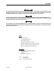
FOREWORD ALL SAFETY-RELATED BULLETINS MUST BE ACCOMPLISHED ON THIS PRODUCT. JLG INDUSTRIES, INC. MAY HAVE ISSUED SAFETYRELATED BULLETINS FOR THIS JLG PRODUCT. CONTACT JLG INDUSTRIES, INC. OR THE LOCAL AUTHORIZED JLG DEALER FOR INFORMATION REGARDING SAFETY-RELATED BULLETINS WHICH MAY HAVE BEEN ISSUED FOR THIS PRODUCT. FOR THE PURPOSE OF RECEIVING SAFETY-RELATED BULLETINS, IT IS IMPORTANT THAT THE CURRENT OWNER OF THIS UNIT ENSURES JLG INDUSTRIES, INC. HAS UPDATED OWNERSHIP INFORMATION.
FOREWORD TRAILER IDENTIFICATION TRAILER NUMBER MODEL NUMBER SERIAL NUMBER VIN NUMBER 1 2 3 4 5 6 7 8 9 10 11 12 d – Triple-L-Trailer – 3121224
NEW PRODUCT WARRANTY NEW PRODUCT WARRANTY 1. WARRANTY. JLG Industries, Inc. (“Manufacturer”) warrants each new product made by it to be free from defects in material or workmanship for twelve months from the date of initial sale, lease, rental, or other disposition of such product.
NEW PRODUCT WARRANTY REVISION LOG Original Issue - May 23, 2003 Revised - August 7, 2003 Revised - March 3, 2004 Revised September 30, 2004 (Edited to 0010598 Rev 7, 0010599 Rev 9, 0010600 Rev 6, 0010601Rev 9, 0010602 Rev 10) Revised - October 4, 2004 Revised - February 25, 2005 Revised - June 27, 2005 Revised - August 22, 2005 Revised - May 24, 2006 Revised - August 28, 2006 Revised - December 5, 2007 Revised - January 17, 2008 Revised - December 21, 2010 Revised - October 11, 2012 f – Triple-L-Trailer
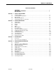
TABLE OF CONTENTS TABLE OF CONTENTS FOREWORD . . . . . . . . . . . . . . . . . . . . . . . . . . . . . . . . . . . . . . . . . . . . . . . . . . . . . . . . . . . . . . . . . .a NEW PRODUCT WARRANTY . . . . . . . . . . . . . . . . . . . . . . . . . . . . . . . . . . . . . . . . . . . . . . . . . . . .e REVISION LOG. . . . . . . . . . . . . . . . . . . . . . . . . . . . . . . . . . . . . . . . . . . . . . . . . . . . . . . . . . . . . . . .f SECTION 1 - SAFETY PRECAUTIONS 1.1 1.2 1.3 1.4 1.
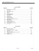
TABLE OF CONTENTS (Continued) LIST OF FIGURES FIGURE NO. 1-1. 1-2. 2-1. 2-2. 2-3. 2-4. 3-1. 3-2. 3-3. 4-1. 4-2. 4-3. 4-4. 4-5. 4-6. 4-7. 4-8. 4-9. 4-10. 4-11. 4-12. TITLE PAGE NO. VIN Label & Tire Information Label . . . . . . . . . . . . . . . . . . . . . . . . . . . . . . . . . . . . . . . . . . . . . . . . .1-4 Decal Location. . . . . . . . . . . . . . . . . . . . . . . . . . . . . . . . . . . . . . . . . . . . . . . . . . . . . . . . . . . . . . . . .1-6 Trailer Features . . . . . . . . . . . . . .
SECTION 1 - SAFETY PRECAUTIONS SECTION 1. SAFETY PRECAUTIONS 1.1 SAFETY INFORMATION 1.3 MAJOR HAZARDS Safety Information, Alert Symbols, and Signal Words An owner’s manual that provides general trailer information cannot cover all of the specific details necessary for the proper combination of every trailer, tow vehicle and hitch. Therefore, you must read, understand and follow the instructions given by the tow vehicle and trailer hitch manufacturers, as well as the instructions in this manual.
SECTION 1 - SAFETY PRECAUTIONS Anticipate the trailer “swaying.” Swaying is the trailer reaction to the air pressure wave caused by passing trucks and busses. Continued pulling of the trailer provides a stabilizing force to correct swaying. Do not apply the brakes to correct trailer swaying. Check rear view mirrors frequently to observe the trailer and traffic. Use lower gear when driving down steep or long grades. Use the engine and transmission as a brake.
SECTION 1 - SAFETY PRECAUTIONS TRAILER TIRES WILL BE INFLATED TO HIGHER PRESSURES THAN PASSENGER VEHICLE TIRES. UNDER-INFLATED FRONT TIRES ON THE TOWING VEHICLE COULD CAUSE STEERING PROBLEMS. LOW PRESSURE IN THE REAR TIRES OF THE TOWING VEHICLE COULD CAUSE THE VEHICLE TO SWAY. Trailer wheels and lug nuts are subjected to significant side loads during tow. Before each tow, visually inspect the lug nuts for loosening.
SECTION 1 - SAFETY PRECAUTIONS 2 1 1. VIN Label 2. Tire Information Label Figure 1-1. VIN Label & Tire Information Label Unsafe Load Distribution Uneven load distribution can cause tire, wheel, axle or structural failure. Be sure your trailer is properly loaded. A proper weight distribution is equal, right to left; and creates a tongue weight that is in the proper range for stable trailer handling (between 10-15% of the total weight of the cargo and the trailer).
SECTION 1 - SAFETY PRECAUTIONS Standard mirrors usually do not provide adequate visibility for viewing traffic to the sides and rear of towed trailer. You must provide mirrors that allow you to safely observe approaching traffic. Modifying the Trailer Essential safety items can be damaged by altering your trailer. Even simply driving a nail or screw to hang something can damage an electrical circuit, hydraulic line or other feature of the trailer.
SECTION 1 - SAFETY PRECAUTIONS 1 12 1 6 7 13 8 9 10 11 4 12 Figure 1-2.
SECTION 1 - SAFETY PRECAUTIONS Table 1-1.
SECTION 1 - SAFETY PRECAUTIONS NOTES: 1-8 – Triple-L-Trailer – 3121224
SECTION 2 - TRAILER OPERATION SECTION 2. TRAILER OPERATION 2.1 TRAILER MODELS Triple-L™ Trailers employ a unique trailer deck design to make loading and unloading easier. The trailer deck can be lowered to the ground while remaining level, allowing equipment to be rolled or driven directly onto the trailer deck. Table 2-1.
SECTION 2 - TRAILER OPERATION Production Option and Accessory Weights Any time a trailer is equipped with a production option or accessory or one of these components is added to a trailer, the weights listed in the following table must be subtracted from the rated vehicle capacity weight. NOTE: The specified options and accessories must be considered part of cargo weight.
SECTION 2 - TRAILER OPERATION 5 Shown with cover open on this side 4 18 3 8 6 20 9 2 7 10 15 13 21 12 12 16 16 14 Figure 2-1.
SECTION 2 - TRAILER OPERATION 2.2 TRAILER FEATURES 1. Rails (Not Shown) - These surround the front and sides of the deck and provide a means to aid in the proper placement of cargo. 2. Storage - This compartment is used to secure the owners manual, tools and other items. 15. Serial Number - This is a 17 digit number, also referred to as the Vehicle Identification Number (VIN), that can be found on the identification plate and stamped on the frame of the trailer. 16.
SECTION 2 - TRAILER OPERATION 2.3 GENERAL 2.4 COUPLER Trailer VIN Information The Trailer Features figure shows the location of the Trailer Identification Plate on your trailer. Mfd. By: JLG Industries, Inc - McConnellsburg, PA--USA Phone 877-JLG-LIFT DATE MODEL PNBV/GVWR (kg/lb) RIMS PNBE/GAWR (ea.axle)(kg/lb) TIRES INFL C (KPa/psi) THIS VEHICLE CONFORMS TO ALL APPLICABLE U.S. FEDERAL MOTOR VEHICLE SAFETY STANDARDS IN EFFECT ON THE DATE OF MANUFACTURE. V.I.N. No.
SECTION 2 - TRAILER OPERATION 2.6 BATTERY (OPTION) . Battery The battery is carried on the trailer and is used for powering the motor running the hydraulic pump. If the trailer has electric brakes, this same battery is used for power to the break-away switch. Batteries are considered an optional item which can be purchased with the trailer or obtained locally. The battery should be a 12 volt deep cycle.
SECTION 2 - TRAILER OPERATION 2.8 TOW VEHICLE AND HITCH INFORMATION Coupler Height Adjustment Follow all of the safety precautions and instructions in this manual and the manuals of the tow vehicle and the hitch to ensure safety of persons, cargo, and satisfactory life of the trailer. Remove the bolts securing the coupler to the mounting bracket. Move the coupler up of down to desired height. Secure with the bolts. For the Pintle Hitch Coupler, torque the two bolts to 225 ft lb (305 Nm).
SECTION 2 - TRAILER OPERATION Automatic Transmission Oil Cooler The automatic transmission of a towing vehicle handles more power when a trailer is being towed. Inadequate cooling will shorten transmission life, and may result in sudden transmission failure. Ask the tow vehicle dealer if it is necessary to install a separate oil cooler for the automatic transmission. Fire Extinguisher A fire extinguisher should be carried in the tow vehicle.
SECTION 2 - TRAILER OPERATION 2. Raise the bottom surface of the coupler to be above the top of the hitch ball. Use the tongue jack if one is provided; otherwise, use wood or concrete blocks to support the trailer tongue. 3. As seen in Figure 2-3., Coupler, slide the collar on the hitch toward the trailer until it opens up to accept the ball from the tow vehicle. 4. Once the hitch on the trailer is open, align the tow vehicle up with the trailer hitch. 5.
SECTION 2 - TRAILER OPERATION Connect the Electrical Cables TO AVOID POSSIBLE INJURY DO NOT TOW THE TRAILER WITH THE PULLPIN REMOVED AND THE BREAKAWAY BRAKE SYSTEM ON BECAUSE THE BRAKES WILL OVERHEAT WHICH CAN RESULT IN PERMANENT BRAKE FAILURE. Connect the trailer lights to the tow vehicle's electrical system using the electrical connectors. Check all lights for proper operation: a. Clearance and Running Lights (Turn on tow vehicle headlights).
SECTION 2 - TRAILER OPERATION 2.10 LOADING THE TRAILER Improper trailer loading causes many accidents and deaths. To safely load a trailer, you must consider: a. Overall load weight For a ball hitch trailer the tongue weight should be between 10% and 15% of the total trailer weight, including the cargo. For example, a trailer, with a loaded weight of 4,000 pounds, should have 10-15% of 4,000 pounds on the tongue. That is, the trailer would have 400 to 600 pounds on its tongue. b.
SECTION 2 - TRAILER OPERATION DO NOT TRANSPORT FLAMMABLE, EXPLOSIVE, POISONOUS OR OTHER DANGEROUS MATERIALS IN YOUR TRAILER. EXCEPTIONS ARE: FUEL IN THE TANKS OF EQUIPMENT BEING HAULED, FUEL STORED IN THE TANK OF AN ON-BOARD GENERATOR. Preparing the Trailer for Loading Before loading cargo onto the trailer: Chock wheels on the left and right sides of the trailer to prevent movement to the front or rear while loading.
SECTION 2 - TRAILER OPERATION NOTE: Be sure that the deck is lowered to seat the weight of the deck on the latch and not the cylinder. BEFORE TOWING THE TRAILER, ENSURE THAT THE TRAVEL LATCH HAS PROPERLY LATCHED INTO PLACE. TIE DOWN ALL LOADS WITH PROPER SIZED FASTENERS, ROPES, STRAPS, ETC. IF YOUR TRAILER IS ENCLOSED OR EQUIPPED WITH AN OPTIONAL TAILGATE, THE DOORS OR TAILGATE MUST BE SECURELY LATCHED BEFORE TOWING THE TRAILER.
SECTION 2 - TRAILER OPERATION 2.11 LIFT TIE DOWN PROCEDURE 2.12 TOWING OPERATIONS The tie downs at the front of the trailer are a fixed length and remain attached to the D-rings in the front corners of the deck. 1. Move the lift onto the trailer and pull forward until the front chains can be attached to the designated tie down points on the lift. THERE SHOULD BE 15 INCHES FROM THE INSIDE FRONT OF THE TRAILER WALL BACK TO THE CENTER OF THE FRONT WHEEL OF THE LIFT. 2.
SECTION 2 - TRAILER OPERATION Safe Trailer Towing Guidelines • Recheck the load tie downs to make sure the load will not shift during towing. • Before towing, check coupling, safety chain, safety brake, tires, wheels and lights. • Check the lug nuts or bolts for tightness. • Check coupler tightness after towing 50 miles. • When equipped with electric brakes, adjust the brake controller to engage the trailer brakes before the tow vehicle brakes. Your dealer can assist you by making this adjustment.
SECTION 2 - TRAILER OPERATION 2.13 PRE-TOW INSPECTION 10. Trailer Battery - Charged and capable of raising trailer deck. Prior to each tow, a Pre-Tow Inspection must be performed. Check each item as specified in the checklist below. 11. Hydraulic Pump - Free of Leaks. Reservoir level full. Proper operation. 12. Deck Descent Alarm - Activates when deck is lowered. DO NOT OVERLOOK VISUAL INSPECTION OF CHASSIS UNDERSIDE.
SECTION 2 - TRAILER OPERATION 2.14 BREAKING-IN A NEW TRAILER Synchronizing the Brake Systems Retighten Lug Nuts at First 10, 25 & 50 Miles Wheel lugs can shift and settle quickly after being first assembled, and must be checked after the first 10, 25 and 50 miles of driving. Failure to perform this check could result in a wheel coming loose from the trailer, causing a crash leading to death or serious injury.
SECTION 2 - TRAILER OPERATION NOTES: 2-18 – Triple-L-Trailer – 3121224
SECTION 3 - ACCESSORIES SECTION 3. ACCESSORIES 3.1 ACCESSORIES • Power: 9 to 15 V DC from vehicle’s battery This section provides some basic information for the safe operation of several accessories. For many accessories, the manufacturer of the accessory has also provided instructions. You must read and follow these instructions before using the accessory. If you are uncertain whether you have all of the instructions, call JLG before operating the accessory.
SECTION 3 - ACCESSORIES Electric Winch Spare Tire Bracket This bolt on bracket attaches directly to the chassis frame. The spare tire is carried neatly over the frame. • 12 Volt • Freespooling clutch • Power In & Out • 12 ft. Remote Control • 50 ft. Steel Cable • 4500 lbs. Rated Line • 5100 lbs Stall Load • Front Trailer Rail Mounting Spare Tire Mounting If your trailer is equipped with the spare tire bracket option, use the following instructions to mount the spare tire to the bracket. 1.
SECTION 3 - ACCESSORIES 3.2 SCISSOR LIFT CHOCKS (IF EQUIPPED) trailer floor and provide a means of positioning the scissor lift in the left/right and front/rear directions. The scissor lift chocks may be pre-installed by the factory in certain trailer models to accommodate certain lifts manufactured by JLG Industries, Inc. (JLG). The Model UT49 or Model 449 are designed to haul a JLG Model 1932E2 Scissor LIft.
SECTION 3 - ACCESSORIES Inspection In addition to the trailer inspection requirements noted in this manual, the chocks must be inspected prior to each loading of the scissor lift for structural discrepancies and loose or missing fasteners. Any discrepancies discovered during this inspection must be corrected before using the chocks. Figure 3-2. Before moving the trailer, ensure that the trailer deck is fully raised and the travel latch is locked into position.
SECTION 4 - SERVICE AND MAINTENANCE SECTION 4. SERVICE AND MAINTENANCE 4.1 INTRODUCTION This section of the manual provides additional necessary information to the operator for proper operation and maintenance of the trailer. Other Publications Available Specific to this Machine: Illustrated Parts Manual................................... 3121226 4.
SECTION 4 - SERVICE AND MAINTENANCE 4.3 INSPECTION AND SERVICE INSTRUCTIONS Axle Bolts, Frame, Suspension, & Structure HAVE TRAILER INSPECTED AN NUALLY AND AFTER ANY IMPACT. To perform many of the inspection and maintenance activities, you must jack up the trailer. Figure 4-1., Jacking Points indicates the general areas where jacks and jack stands may be applied. When jacking and using jack stands, place them so as to clear wiring, brake lines, and suspension parts (springs, torsion bars, etc.).
SECTION 4 - SERVICE AND MAINTENANCE Trailer Structure Welds Because the trailer floor receives the most abuse, it will most likely corrode before any other part of the structure. Using a power washer and a detergent solution, wash the floor and walls of the trailer. Rinse the trailer floor and walls. Fasteners and Frame Members Inspect all of the fasteners and structural frame members for bending and other damage, cracks, or failure. Repair or replace any damaged fastener and repair the frame member.
SECTION 4 - SERVICE AND MAINTENANCE 15 14 1 6 15 1. Cylinder Barrel 2. Cylinder Rod 7 3. Cylinder Head 4. Piston 4 5. Nut, Grade 8 10 11 6. Breather 12 7. Seal 3 8. Seal 9. Rod Wiper 8 13 5 9 10. O-Ring 11. O-Ting 12. Back-up Ring 13. Back-up Ring 14. Clevis Pin 2 15. Cotter Pin 15 14 15 Figure 4-2. Hydraulic Cylinder NOTE: Torque Cylinder Head (3) to 250 - 300 ft lb (339 - 407 Nm). Torque Nut (5) to 180 - 200 ft lb (244 - 407 Nm).
SECTION 4 - SERVICE AND MAINTENANCE TO CYLINDER PORT (ROD END) BATTERY UP DOWN Figure 4-3. Hydraulic Schematic Hydraulic Pump/Motor Specifications: This unitized motor/pump package should be inspected periodically for any fluid leaks and tank oil level. Motor - 12 Volts Tank Capacity - 3 Quarts Pressure Relief Setting - 1900 psi Displacement - 0.138 in^3/rev Full Tank Level - 1" below fill cap when trailer deck is lowered. Fluid Type - DEXTRON II ATF (automatic transmission fluid). Table 4-2.
SECTION 4 - SERVICE AND MAINTENANCE . RESERVOIR MOTOR SWITCH RETURN TUBE ADJUSTABLE RELIEF VALVE FILTER BRACKET SUCTION TUBE DRAIN HOLE REF Figure 4-4. 12 Volt Motor/Pump Parts Relief Valve Adjustment: 1. Loosen Jam Nut 2. Adjust Pressure a. Turn screw clockwise to increase pressure. b. Turn screw counter clockwise to decrease pressure. NOTE: Outlet Port (Pressure) flow must be blocked to make relief valve operate while adjusting. 3.
SECTION 4 - SERVICE AND MAINTENANCE Brake Shoes and Drums Properly functioning brake shoes and drums are essential to ensure safety. You must have your dealer inspect these components at least once per year, or each 12,000 miles. The brakes should be adjusted (1) after the first 200 miles of operation when the brake shoes and drums have "seated," (2) at 3000 miles intervals, (3) or as use and performance requires.
SECTION 4 - SERVICE AND MAINTENANCE . 1 2 3 5 4 6 7 8 23 9 18 22 17 16 10 11 20 21 19 15 14 8 1. Pivot Pin Locknut 2. Washer 3. Parking Brake Lever 4. Anchor Post Locknut 5. Anchor Post and Bushing Sub-Assembly 6. Backing Plate 7. Actuating Lever Arm Assembly 8. Brake Shoe 9. Retractor Spring 10. Actuating Cam 11. Pivot Pin and Cam Assembly 12. Adjusting Screw Spring 14 13 12 13. Adjuster Assembly 14. Shoe Hold Down Spring and Cup 15. Magnet Clip 16. Magnet 17. Magnet Spring 18.
SECTION 4 - SERVICE AND MAINTENANCE 2 1 3 4 5 6 15 12 14 10 11 13* 7 5 1. Screw and Washer Assembly 2. Backing Plate Assembly 3. Brake Cylinder Servo (Duo) 4. Cylinder Push Rod 5. Brake Shoe 6. Anchor Post Washer 7. Retractor Spring 8. Adjusting Screw Spring 10 9 8 9. Adjuster Assembly 10. Hold Down Spring and Cup 11. Brake Mounting Nut 12. Lockwasher 13. Brake Cylinder Servo (Uni) 14. Adjuster Slot Plug 15.
SECTION 4 - SERVICE AND MAINTENANCE Hydraulic (Surge) Brakes (Option) • Hardware - Check all hardware. Check shoe retractor spring, hold down springs, and adjuster springs for stretch or wear. Replace as required. (See Figure 4-6.) If your trailer has hydraulically-operated brakes, they function the same way the hydraulic brakes do on your tow vehicle.
SECTION 4 - SERVICE AND MAINTENANCE 9. Attempt to rotate the wheels in a forward direction. If any of the wheels rotate, the brakes must be adjusted. 4.5 TONGUE JACK Operating Rotate the jack handle clockwise to raise the jack, or counterclockwise to lower the jack. OIL GREASE 4.4 TRAILER CONNECTION TO TOW VEHICLE Coupler and Ball The coupler on the trailer connects to the ball attached to the hitch on the tow vehicle.
SECTION 4 - SERVICE AND MAINTENANCE 4.6 LIGHTS AND SIGNALS 4.7 TRAILER CONNECTIONS Before each tow, check the trailer taillights, stoplights, turn signals and any clearance lights for proper operation. Before each tow, verify that the proper trailer connections have been made. IMPROPER OPERATING TAILLIGHTS, STOPLIGHTS AND TURN SIGNALS CAN CAUSE COLLISIONS. CHECK ALL LIGHTS BEFORE EACH TOW.
3121224 – Triple-L-Trailer – 1870165 D NOTE: The blue and orn/brn breakaway switch wires and the white and black wires are used only with trailers equipped with the electric brakes option. SECTION 4 - SERVICE AND MAINTENANCE Figure 4-8.
SECTION 4 - SERVICE AND MAINTENANCE Battery (Option) 4.8 WHEEL ALIGNMENT A battery operates the hydraulic pump motor that lowers and raises the trailer bed. If the trailer has electric brakes, this same battery supplies the power to operate the trailer brakes if the trailer uncouples from the tow vehicle activating the breakaway brake switch. The battery may be kept charged either by the tow vehicle or by an available trickle charger.
SECTION 4 - SERVICE AND MAINTENANCE 4.10 UNSEALED BEARINGS (HUBS) If your trailer has unsealed axle bearings, they must be inspected and lubricated once a year or 12,000 miles to insure safe operation of your trailer. If a trailer wheel bearing is immersed in water, it must be replaced. If your trailer has not been used for an extended amount of time, have the bearings inspected and packed more frequently, at least every six months and prior to use. Wheel Bearings Figure 4-10.
SECTION 4 - SERVICE AND MAINTENANCE 4.11 DECK BEARING REPLACEMENT . 5. In a clear flat area, lower the deck completely to the ground. 6. A cap may be tack welded on the top of each bearing channel. If so, grind the welds loose and remove all (4) caps. 9. Using a fork lift or hoist, slowly lift the chassis up to allow the bearings to lift out of the bearing channels.
SECTION 4 - SERVICE AND MAINTENANCE 4.12 TIRE AND WHEEL MAINTENANCE Checking Tire Pressure Glossary of Tire and Loading Terminology It is important to check your vehicle's tire pressure at least once a month for the following reasons: 1. Cold Inflation Pressure - The pressure in the tire before you drive. The term cold does not relate to the outside temperature. Rather, a cold tire is one that has not been driven on for at least three hours. • Most tires may naturally lose air over time. 2.
SECTION 4 - SERVICE AND MAINTENANCE Tire Wear Replace the tire before towing the trailer, if the tire treads have less than 1/16-inch depth or the telltale bands are visible. The following tire wear diagnostic chart will help you pinpoint the causes and solution of tire wear problems. The following tire wear diagnostic chart will help you pinpoint the causes and solution of tire wear problems. A bubble, cut or bulge in a sidewall can result in a tire blowout.
SECTION 4 - SERVICE AND MAINTENANCE BS XL RESS XX PSI • AX P RA DI •M AL • • SS LE BE TU PLY RATING•TR EA D X PL I MAXLOA ORD • DX XC XX XX kg X 2X XX • Information on Trailer Tires • SIDEW ANGE ALL DR 2 PL OA IE •L S ES 1. Tire Application - This letter identifies the tire by application. • LT = Light Trucks or Trailers • ST = Trailer use only 2. Tire Width - This three-digit number gives the width in millimeters of the tire from sidewall edge to sidewall edge.
SECTION 4 - SERVICE AND MAINTENANCE Lug Nuts 25 and 50 miles of driving and visually inspect before each tow thereafter. It is extremely important to apply and maintain proper wheel mounting torque on the trailer axle. Torque wrenches are the best method to ensure the proper amount of torque is being applied to a nut. NOTE: Wheel nuts must be installed and maintained at the proper torque to prevent loose wheels, broken studs, and possible dangerous separation of wheel from the axle.
SECTION 4 - SERVICE AND MAINTENANCE 4.13 TIRE SAFETY INFORMATION NOTE: This portion of the User’s Manual contains tire safety information as required by 49 CFR 575.6. Steps For Determining Correct Load Limit – Trailer pressure that enables a tire to support the load, so proper inflation is critical. The proper air pressure may be found on the certification/VIN label and/or on the Tire Placard. This value should never exceed the maximum cold inflation pressure stamped on the tire.
SECTION 4 - SERVICE AND MAINTENANCE Steps For Determining Correct Load Limit – Tow Vehicle 1. Locate the statement, “The combined weight of occupants and cargo should never exceed XXX lbs.,” on your vehicle’s placard. 2. Determine the combined weight of the driver and passengers who will be riding in your vehicle. 3. Subtract the combined weight of the driver and passengers from XXX kilograms or XXX pounds. 4. The resulting figure equals the available amount of cargo and luggage capacity.
SECTION 4 - SERVICE AND MAINTENANCE Safety First – Basic Tire Maintenance Properly maintained tires improve the steering, stopping, traction, and load-carrying capability of your vehicle. Under-inflated tires and overloaded vehicles are a major cause of tire failure. Therefore, as mentioned above, to avoid flat tires and other types of tire failure, you should maintain proper tire pressure, observe tire and vehicle load limits, avoid road hazards, and regularly inspect your tires.
SECTION 4 - SERVICE AND MAINTENANCE Information On Passenger Tires Tire Tread The tire tread provides the gripping action and traction that prevent your vehicle from slipping or sliding, especially when the road is wet or icy. In general, tires are not safe and should be replaced when the tread is worn down to 1/16 of an inch. Tires have built-in treadwear indicators that let you know when it is time to replace your tires.
SECTION 4 - SERVICE AND MAINTENANCE Speed Rating The speed rating denotes the speed at which a tire is designed to be driven for extended periods of time. The ratings range from 99 miles per hour (mph) to 186 mph. These ratings are listed below. Note: You may not find this information on all tires because it is not required by law.
SECTION 4 - SERVICE AND MAINTENANCE Tire Safety Tips Glossary Of Tire Terminology Preventing Tire Damage • Slow down if you have to go over a pothole or other object in the road. • Do not run over curbs or other foreign objects in the roadway, and try not to strike the curb when parking. Tire Safety Checklist • Check tire pressure regularly (at least once a month), including the spare. • Inspect tires for uneven wear patterns on the tread, cracks, foreign objects, or other signs of wear or trauma.
SECTION 4 - SERVICE AND MAINTENANCE Gross Axle Weight Rating The maximum weight that any axle can support, as published on the Certification / VIN label on the front left side of the trailer. Actual weight determined by weighing each axle on a public scale, with the trailer attached to the towing vehicle. Gross Vehicle Weight Rating The maximum weight of the fully loaded trailer, as published on the Certification / VIN label.
SECTION 4 - SERVICE AND MAINTENANCE heavy duty brakes, ride levelers, roof rack, heavy duty battery, and special trim. Radial Ply Tire A pneumatic tire in which the ply cords that extend to the beads are laid at substantially 90 degrees to the centerline of the tread. Recommended Inflation Pressure This is the inflation pressure provided by the vehicle manufacturer on the Tire Information label and on the Certification / VIN tag.
C A LIF O R N IA N P R O P O S IT IO N 6 5 B AT T E R Y W A R N IN G B a tte ry p o s ts , te rm in a ls a n d re la te d a c c e s s o rie s c o n ta in le a d a n d le a d c o m p o u n d s , c h e m ic a ls k n o w n to th e S ta te o f C a lifo rn ia to c a u s e c a n c e r a n d re p ro d u c tiv e h a rm . B a tte rie s a ls o c o n ta in o th e r h a rm fu l c h e m ic a ls k n o w n to th e S ta te o f C a lifo rn ia .
3121224 Corporate Office JLG Industries, Inc. 1 JLG Drive McConnellsburg PA. 17233-9533 USA (717) 485-5161 (717) 485-6417 JLG Worldwide Locations JLG Industries (Australia) P.O. Box 5119 11 Bolwarra Road Port Macquarie N.S.W. 2444 Australia JLG Latino Americana Ltda. Rua Eng. Carlos Stevenson, 80-Suite 71 13092-310 Campinas-SP Brazil +55 19 3295 0407 +61 2 65 811111 +55 19 3295 1025 +61 2 65 810122 JLG Deutschland GmbH Max-Planck-Str.