Operation, Safety, Maintenance and service Manual Original Instructions - Keep this manual with the machine at all times.
JLG LIFT FOREWORD For: • Accident Reporting • Product Safety Publications • Current Owner Updates • Questions Regarding Product Safety • Standards and Regulations Compliance Information • Questions Regarding Special Product Applications • Questions Regarding Product Modifications Contact: Product Safety and Reliability Department JLG Industries, Inc.
JLG LIFT FOREWORD REVISION LOG Rev.
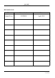
BOOM LIFT MODELS X17JPLUS JLG TABLE OF CONTENTS CHAPTER 1 PRESENTATION ....................................................................................Page 08 CHAPTER 2 2.1 2.1.1 2.1.2 2.1.3 2.1.4 2.1.4.1 2.1.4.2 2.1.4.3 2.1.4.4 2.1.4.5 2.1.5 2.2 2.3 2.3.1 2.3.2 2.3.3 TECHNICAL INFORMATION ...........................................................Page 09 Description of the machine ...................................................................Page 09 Control position ..........................
BOOM LIFT MODELS X17JP JLG 6.4.1 6.4.2 6.4.3 6.4.4 6.4.5 6.4.6 6.4.7 6.4.8 6.4.9 6.4.10 6.4.11 6.4.12 6.4.13 6.5 6.5.1 6.5.2 6.5.3 6.5.4 6.5.5 6.5.6 6.6 6.7 6.8 6.8.1 6.8.2 6.8.3 6.8.4 6.8.5 6.8.6 CHAPTER 7 7.1 7.2 7.3 7.4 7.5 7.6 7.7 7.8 7.8.1 7.9 7.10 7.11 7.11.1 7.11.2 7.11.3 7.11.4 7.12 7.13 7.13.1 7.14 2 Preliminary checks before starting work ...........................................Page 70 Starting the petrol/diesel engine .........................................................
BOOM LIFT MODELS X17JPLUS JLG 7.15 7.16 7.17 7.18 7.19 7.20 7.21 7.22 7.22.1 7.22.2 7.22.3 7.22.4 7.23 7.23.1 7.23.2 7.23.3 7.23.3.1 7.23.3.2 7.23.3.3 7.23.3.4 7.24 CHAPTER 8 8.1 8.2 Checking the condition of the filter cartridge ....................................Page 128 Checking that all the plates are present on the machine and intact .................................................................................................Page 128 Checking the operating pressure of the hydraulic system ......
BOOM LIFT MODELS X17JPLUS JLG PREFACE The aim of this manual is to provide the user with the necessary instructions and essential operating procedures to ensure correct and safe use of the machine for its intended purpo‑ ses, as well as to prevent serious injury to the operator and other persons. IMPORTANT IT IS MANDATORY TO KEEP TO ALL THE INSTRUCTIONS GIVEN IN THIS MANUAL. THIS MANUAL MUST BE CAREFULLY READ AND UNDERSTOOD BEFORE OPERA‑ TING THE MACHINE.
BOOM LIFT MODELS X17JPLUS JLG Note: All of the photos and drawings in this manual have been added to simplify com‑ prehension by the reader. Your machine may differ from the photos and drawings provi‑ ded.
BOOM LIFT MODELS X17JPLUS JLG EC DECLARATION OF CONFORMITY EC DECLARATION OF CONFORMITY Manufacturer Address Technical File: Authorised contact Machine Type: JLG Industries Inc 1 JLG Drive McConnellsburg PA17233 USA JLG Industries Inc JLG Technology & Development Centre Bruntingthorpe Aerodrome & Proving Ground Lutterworth, Leicestershire LE17 5QS United Kingdom.
BOOM LIFT MODELS X17JPLUS JLG EC DECLARATION OF CONFORMITY Manufacturer Address Machine Type: JLG Industries Inc 1 JLG Drive McConnellsburg PA17233 USA Mobile Elevating Work Platform Model Type: ... Serial Number: ... Document Control: HINOWA S.p.A Via Fontana - 37054 Nogara Italy Technical File: JLG Industries Inc JLG Technology & Development Centre Bruntingthorpe Aerodrome & Proving Ground Lutterworth, Leicestershire LE17 5QS United Kingdom. Measured Lwa dB(A) ... Lwa dB(A) ... kW ...
BOOM LIFT MODELS X17JPLUS JLG 1. PRESENTATION This manual describes the warning signs used to draw the reader’s attention to several parti‑ cularly important warnings. The safety warnings are divided into two main types, which are identified and described below.
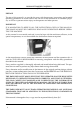
BOOM LIFT MODELS X17JPLUS JLG 2. TECHNICAL INFORMATION 2.1. DESCRIPTION OF THE MACHINE The JLG machine is a self‑propelled hydraulic lifting device, equipped with a rotating work basket positioned at the top of an extendable articulated structure, which also rotates. The JLG lifting device is destined for the POSITIONING OF PERSONS AND THEIR EQUIP‑ MENT AND MATERIALS IN HIGH POSITIONS WITH RESPECT TO GROUND LEVEL. 2.1.
BOOM LIFT MODELS X17JPLUS JLG CONTROL POSITION ON THE GROUND: There is a second control position available for the tracked part of the machine. This is not in a fixed position but rather can be located on the ground within a radius of 2.5 m from the basket attachment. To control the machine from this position, the operator uses the same remote control, removing it from its housing in the basket and using the cable provided.
BOOM LIFT MODELS X17JPLUS JLG If an operator is in the basket, it is forbidden to move the structure from the ground posi‑ tion, unless in an emergency situation (sudden operator illness, technical fault). PHOTO 1 PHOTO 2 There is a control position available only for scheduled and unscheduled maintenance opera‑ tions, placed near the electrical components compartment on the machine.
BOOM LIFT MODELS X17JPLUS JLG 2.1.2 MACHINE IDENTIFICATION PLATE The manufacturer plate is placed on the protection of the aerial part hydraulic distributor. The drawing is shown below. xsm1;Manufactured by HINOWA S.p.A. Via Fontana 37054 NOGARA (VR) ITALY JLG Industries. Inc - McConnellsburg. PA - USA Model Serial number Date of manufacture kg G.V.W. (Dry) 1° MAXIMUM ALLOWABLE OPERATING INCLINATION = + MAX 12.
BOOM LIFT MODELS X17JPLUS JLG 2.1.3 OVERALL DIMENSIONS OF THE MACHINE Maximum length in travel configuration with basket installed ......................4529 mm Track width ..............................................................................................................798/1086 mm Maximum height in travel configuration with foot plates removed ..............2000 mm Maximum attachment angle..................................................................................
BOOM LIFT MODELS X17JPLUS JLG 2.1.4 TECHNICAL SPECIFICATIONS PLATFORM CAPACITY 230 kg PLATFORM HEIGHT (floor) 14,96 m MAX WORKING HEIGHT 17,06 m STANDARD BASKET DIMENSIONS 1335 x 690 x H1100 mm HORIZONTAL EXTENSION 7,00 m MAX HORIZONTAL OUTREACH 7,50 m ROTATION (non-continuous) 360° BASKET ROTATION MAX GROUND REACTION FORCE FOR EACH STABILISER MAX GROUND PRESSURE FOR EACH STABILISER 124° (+/- 62°) NO. OF OPERATORS NO.
BOOM LIFT MODELS X17JPLUS JLG 2.1.4.1 TECHNICAL DATA – PETROL ENGINE Make/Model ................................................................................HONDA iGX440 Fuel/Cooling ................................................................................PETROL/AIR Power SAEJ1349 ..........................................................................9,5 Kw (12,7cv) / 3600rpm Max speed ....................................................................................3600 rpm Maximum torque ..
BOOM LIFT MODELS X17JPLUS JLG 2.1.4.4 ELECTRICAL SYSTEM TECHNICAL SPECIFICATIONS THERMIC Battery ................................................................................55 Ah ‑ 240 A ‑ 12V Alternator petrol engine ..................................................20 A (3600 rpm) Alternator diesel engine ..................................................14 A (3000 rpm) Electric motor: ‑ rated voltage..........................................230 V ‑ frequency ..........................................
BOOM LIFT MODELS X17JPLUS JLG 2.1.5 TERMINOLOGY To make the contents of this manual easier to understand, the diagram provided below illu‑ strates the terms used to identify the parts of the platform.
BOOM LIFT MODELS X17JPLUS JLG 2.2 GENERAL SAFETY STANDARDS DANGER ATTENZIONE The functioning of the MEWPS must be in compliance with international standards of refe‑ rence (see paragraph “NORMATIVE REFERENCES” in the first pages of the manual) and national or regional standards if stricter. The operator must read, understand and follow all the instructions and warnings, contained in this manual and on the machine, regarding the safe use of the MEWPS.
BOOM LIFT MODELS X17JPLUS JLG IMPORTANTE WARNING USE THE TYPE‑APPROVED AND CERTIFIED SAFETY HARNESSES. BEFORE WORKING AT A HEIGHT, MAKE SURE THAT THE SAFETY HARNESSES ARE COR‑ RECTLY FASTENED AND CONNECTED TO THE ANCHORAGE POINTS ON THE BASKET. THE USE OF HARNESSES IS COMPULSORY IN ACCORDANCE WITH LOCAL LEGISLATION IN EACH INDI‑ VIDUAL COUNTRY. IN COUNTRIES WHERE THE LAW DOES NOT REQUIRE THE USE OF SUCH SAFETY SYSTEMS, THE EMPLOYER AND/OR USER IS RESPONSIBLE FOR CHOOSING THE SYSTEM TO BE USED.
BOOM LIFT MODELS X17JPLUS JLG • Cleaning the machine Always park the machine as shown in the figure in point 2.1.5. DANGER ATTENZIONE When washing the machine, the ignition block must be disengaged, the key removed and the emergency stop button pressed. • Washing the outside of the machine Never use flammable liquids. Adopt the above safety measures to prevent sparks due to short‑circuits.
BOOM LIFT MODELS X17JPLUS JLG IMPORTANTE WARNING Only use dry detergents, in accordance with the manufacturer’s instructions. Never remove covers, guards and the like. ‑ Clean the electrical system using a dry, non‑metallic brush and low pressure air. • After cleaning Dry the machine carefully before starting it again (for example using compressed air).
BOOM LIFT MODELS X17JPLUS JLG 2.3 SAFETY WARNINGS 2.3.1 GENERALITIES To avoid accidents, before starting work and before performing any maintenance operations, it is necessary to read, understand and follow all the precautions and warnings contained in this manual. The user/operator of the machine must decline all responsibility for operation until having read this manual and fully understood how to use the machine under the supervision of an expert and qualified operator.
BOOM LIFT MODELS X17JPLUS JLG 2.3.3 PICTOGRAMS POSITIONED ON THE MACHINE Here we report the positions of the various boards with pictograms on the machine.
BOOM LIFT MODELS X17JPLUS JLG 24 X17JPR0020413
BOOM LIFT MODELS X17JPLUS JLG POS. CODE Q.ty POS. CODE Q.
BOOM LIFT MODELS X17JPLUS JLG LANGUAGE STICKERS POS. Q.ty POS. 1 5 2 2 1 L1 L2 L3 L4 L5 CODE 172428DE 06562800 06561200 06462900 06462300 073191DE L1 L2 L3 L4 L5 172428ES 06562900 06561200 06463000 06462400 073191ES 1 5 2 2 1 172428NL 06563000 06561200 06463100 06462500 073191NL 1 5 2 2 1 CODE Q.
BOOM LIFT MODELS X17JPLUS JLG X17JPR0020413 27
BOOM LIFT MODELS X17JPLUS JLG 28 X17JPR0020413
BOOM LIFT MODELS X17JPLUS JLG X17JPR0020413 29
BOOM LIFT MODELS X17JPLUS JLG Pos Code qty 1001125483 06506400 3 1 06520600 2 17 07264700 1 17 (from serial number C170000330) 1 2 3 4 5 6 7 8 9 07394800 1 LANGUAGE STICKERS Pos Code qty Pos Code qty 1 171877IT 30 1 07188700 1 1 171877GB 07201700 13 07188100 1 13 07202100 1 Pos Code qty Pos Code qty 1 171877FR 07201800 1 1 171877DE 07188800 1 13 07202200 1 13 07188200 1 X17JPR0020413
BOOM LIFT MODELS X17JPLUS JLG Pos Code 1 171877ES 07201900 13 Pos Code qty 1 1 171877NL 07188900 1 07202300 1 13 07188300 1 Pos Code qty Pos Code qty 1 171877PT 07202000 1 1 171877SW 07189000 1 13 07202400 1 13 07188400 1 Pos Code qty Pos Code qty 1 171877DA 07189100 1 1 171877NO 07189200 1 13 07188500 1 13 07188600 1 X17JPR0020413 qty 31
BOOM LIFT MODELS X17JPLUS JLG Name Description Identikit 06040300 WARNING KEEP SAFE DISTANCE 06040500 SENSE OF MOVING UNDERCARRIAGE 06040800 CRUSHING HAZARD PERSON 06040500 06040300 Code DEFINED AS THE DIRECTION FORWARD 06040900 OBLIGATION TO READ THE MANUAL BEFORE USE OF MACHINE 1703814 FIXING POINT FOR TRANSPORT 06040900 06040800 INDICATES CORRECT FIXING POINT FOR TRANSPORT OF THE MACHINE 1703814A 06041300 32 INDICATES AREAS WHERE THERE IS A CRUSHING HAZARD DANGER OF CRU‑ PERSON SHI
BOOM LIFT MODELS X17JPLUS JLG Code Name 06056300 DANGER HIGHT TEMPERATURE 06060000 ENGINE OIL LEVEL INDICATES CORRECT LIFTING POINTS FOR LIFT THE MACHINE 06085900 0606 00 00 00 63 05 06 LIFTING POINT Identikit 0 60 4 40 0 0 06044000 Description EMERGENCY DEVI‑ CE FOR AERIAL PART 06086000 DEVICE THAT ALLOWS TO EXCLUDE THE EMERGENCY DEVI‑ SAFETY OF THE CE FOR UNDERCAR‑ UNDERCARRIAGE IN RIAGE CASE OF EMERGENCY OPERATIONS 06086600 WARNING KEEP SAFE DISTANCE AND CRUSHING HAZARD PERSON 060866
BOOM LIFT MODELS X17JPLUS JLG 06165000 HYDRAULIC OIL LEVEL 1701499 FORBIDDEN LIFTING POINT Description Identikit 6 5 0 00 Name 0 61 Code 1701499 1001125483 DO NOT WASH WITH WATER GROUNDING 06998800 HAND PUMP LEGEND QUICK INSTRUCTIONS FOR USING THE EMER‑ GENCY HAND PUMP BE CAREFULL AT WORK USING SAFETY HAR‑ NESSES, USE PROTECTI‑ VE EQUIPMENT (HEL‑ MET), PROHIBITION OF WELD ON THE MACHI‑ NE, PROHIBITION OF USE SYSTEMS TO INCREASE THE AREA OF WORK INSIDE THE BASKET , PROHIBITION OF WORKING I
BOOM LIFT MODELS X17JPLUS JLG Code Name Description Identikit WARNING Explosion, Electric Shock and Corrosion Hazard BATTERY PACK WARNINGS Li-ion - Only qualified service personnel are authorized to handle and replace the battery pack and the fuse. - Operating and recharging outside temperature range: 0°C to 40°C. Do not leave for a long time in direct sunlight or an unventilated place. - Recharge only in a dry and isolated place that is away from flammable materials.
BOOM LIFT MODELS X17JPLUS JLG Description 1704277 ANCHOR POSITION IN BASKET INDICATES THE POSI‑ TION OF THE ANCHOR HOOKS TO WHICH FASTEN THE OPERA‑ TOR’S SAFETY SLING 07350300 LIFTING POINTS WITH FORKLIFT INDICATES THE LIF‑ TING POINTS WITH FORKLIFT Identikit 1704277A Name 07350300A Code REPLACE STICKERS AND PLATES IF THERE IS ANY SIGN OF WEAR. FAILURE TO HEED ANY WARNINGS DUE TO A SAFETY STICKER BEING DAMAGED, LOST OR IGNORED MAY CAUSE SERIOUS ACCIDENTS.
BOOM LIFT MODELS X17JPLUS JLG 3 SAFETY DEVICES The information given below concerning the safety devices are provided to the user in order to allow him/her to understand the machine behaviour and possible work sequences; moreo‑ ver, in this way it is possible to identify any breakdowns with greater precision and to sup‑ ply more detailed information to the after‑sales service for quicker, less expensive interven‑ tions.
BOOM LIFT MODELS X17JPLUS JLG 3.1 BATTERY CUTOUT SWITCH THERMIC MOTOR LITHIUM MOTOR This device, located on the left side of the electrical components compartment, is used to iso‑ late the machine’s electrical circuit, stopping any movements. It is well‑visible and easily accessed without using tools. It only needs to be activated for prolonged machine downtime or maintenance operations.
BOOM LIFT MODELS X17JPLUS JLG 3.3 CYLINDER STOP VALVES The stabiliser cylinders have a double stop valve which in case of system breakdown or hose breakage stops the cylinder preventing dangerous platform instability situations. All cylinders that move the aerial part of the platform structure are fitted with a stop valve which in case of system breakdown or hose breakage stops the cylinder preventing the basket from falling due to gravity.
BOOM LIFT MODELS X17JPLUS JLG 3.5 STABILISER POSITION MICROSWITCHES, STANDARD VERSION The position of the stabilisers and their contact with the ground are detected by 4 microswit‑ ches positioned near the stabiliser cylinder rod fastening pin. The microswitches fixed to the stabiliser must be released when the stabiliser rests on the ground. Check the correct operation of the microswitches every day. 3.
BOOM LIFT MODELS X17JPLUS JLG 3.7 BASKET LOAD SENSOR The load sensor on the basket is made up of a basket sup‑ port with two shafts that only allow the vertical move‑ ment of the basket. The basket support is supplied by the load cell itself. Two strain gauges are positioned inside the sensor positioned under the basket and convert the relative weight inside the basket into an electrical signal.
BOOM LIFT MODELS X17JPLUS JLG 3.8 CONTROL PROTECTION A protection structure is provided to protect the remote control against the accidental fall of objects from above and involuntary activation by the operator. Always make sure that this protection structure is intact before using the machine. 3.9 SPIRIT LEVEL The spirit level is positioned on the turret and it is readily visible from the basket and from the ground.
BOOM LIFT MODELS X17JPLUS JLG 3.10 PIN LOCKING BOLTS AND NUTS 1 2 3 All the pins used on the JLG platform were treated against wear and are fitted with flanges (1) to prevent them from rotating inside their seat. Some pins have bolts to stop rotation (2) while others pins have a joint in the structure of the machine. The pins in the most delicate positions are threaded at the ends and are fitted with self‑ locking nuts (3) or self‑locking threaded ring nuts to prevent the structure from subsiding.
BOOM LIFT MODELS X17JPLUS JLG 4 INSTRUMENTS AND CONTROLS Below is a description of all the controls and indicators present on the platform; each device has a sticker that briefly describes its function applied nearby, often containing symbols that are used to ensure quick and clear understanding. Before using the platform, the following descriptions must be read in order to gain in‑depth knowledge of the functions of each devi‑ ce and to be aware of any suggestions provided by the manufacturer.
BOOM LIFT MODELS X17JPLUS JLG 4.1.1 DISPLAY The display is used to view the status of the machine and the operating information neces‑ sary or useful for the operator. When the machine’s main control board is powered via the engine key, the information to be shown on the display is sent to the remote control. This operation has a variable duration.
BOOM LIFT MODELS X17JPLUS JLG POSITION 3: Position 3 displays the engine/motor selection and the engine status. Petrol/diesel engine Electric motor An X on the icon indicates that the engine/motor is off, no X indicates that it is on. POSITION 4: Position 4 displays the selected speed or the reduced speed for the Lithium: SLOW NORMAL FAST REDUCED POSITION 5: Position 5 displays the icon confirming that overhead movements are enabled.
BOOM LIFT MODELS X17JPLUS JLG When the load sensor measures a load exceeding the allowed work load ‑ 230 kg ‑ the main screen disappears for three seconds, replaced by the overload error display, the audible war‑ ning is activated, then the overload icon appears in position 5 in place of the icon enabling the overhead movements. OVERLOAD ERROR DISPLAY POSITION 6: Position 6 displays the icon confirming that track movements (stabilisers, tracks, track exten‑ sion) are enabled.
BOOM LIFT MODELS X17JPLUS JLG POSITION 7: Position 7 is used for functional signals: Emergency STOP pressed Signals that one of the emergency stop buttons on the machine has not been released. BATTERY VOLTAGE BELOW MINIMUM LIMIT. Indicates that the battery charge level is below the minimum limit allowed. If this message appears, it is advisable to recharge the battery, either by keeping the diesel or petrol engine on, or by connecting to the network.
BOOM LIFT MODELS X17JPLUS JLG The angular position control does not work correctly The machine has a CANBUS line connection fault. A faulty or incorrect electronic board (card) has been installed, or alter‑ natively an incorrect software version has been loaded. POSITION 8: Position 8 displays the battery charge status or the icon indicating the battery is being recharged in the Lithium version.
BOOM LIFT MODELS X17JPLUS JLG 1 2 3 4 5 6 7 8 FORWARDS 5 07071000B 6 BACKWARDS 9 MOVEMENT CONTROLLED JOYSTICK JOYSTICK SHIFTING DIRECTION AERIAL MOVEMENTS ENABLED FORWARDS LEFT TRACK FORWARDS BACKWARDS LEFT TRACK BACKWARDS FORWARDS 1st‑2nd ARM UP BACKWARDS 1st‑2nd ARM DOWN FORWARDS 3rd ARM UP BACKWARDS 3rd ARM DOWN FORWARDS EXTENSION ARM IN BACKWARDS EXTENSION ARM OUT FORWARDS BASKET ANTICLOCKWISE ROTATION BACKWARDS BASKET CLOCKWISE ROTATION 1 2 3 4 5 50 X17JPR002
BOOM LIFT MODELS X17JPLUS JLG FORWARDS JIB OPENING BACKWARDS JIB FOLDING FORWARDS ANTICLOCKWISE ROTATION BACKWARDS CLOCKWISE ROTATION FORWARDS RIGHT TRACK FORWARDS BACKWARDS RIGHT TRACK BACKWARDS R CLOSE BASKET LEVELLING L OPEN BASKET LEVELLING 6 7 8 9 4.1.3 PUSH BUTTONS The buttons have a dual function: they can be used to select machine functions or as numeri‑ cal keys in the service submenus.
BOOM LIFT MODELS X17JPLUS JLG BUTTON 2: Enters the menu for the manual movements of the individual stabilisers. BUTTONS 3‑9: Used to extend and narrow the tracked undercarriage. BUTTON 4 Used to enable control of the emergency descent from the basket. Confirmation that the ope‑ ration is enabled is displayed on the screen in position 8.
BOOM LIFT MODELS X17JPLUS JLG BUTTON 5: Used to select the travel speed and the engine/motor speed. There are three speeds available: • SLOW: engine at 1,500 rpm for the operation of the aerial part, at 2,200 rpm for the operation of the carriage. Minimum possible speed for the tracks. • NORMAL: variable rpm according to the selected movement. Travel motors always with maxi‑ mum displacement, therefore medium travel speed • FAST: variable rpm according to the selected movement.
BOOM LIFT MODELS X17JPLUS JLG BUTTON 10 (ONLY PETROL VERSION): Allows the preheating of the petrol engine. One pressure on the button sets the engine at 2200 rpm for 20 seconds, in order to heat the engine and improve the initial phases of use. BUTTON 11: Allows the engine to be switched on/off. If the button is pressed with the engine on, this will be stopped. BUTTON 12: Allows the electric motor to be switched on/off. If the button is pressed with the engine on, this will be stopped.
BOOM LIFT MODELS X17JPLUS JLG 4.2 FOOTSWITCH Inside of the basket is fitted a footswitch device that must be pushed to allow the movement of the machine from the basket. If you try to move the machine without the footswitch pushed the movement will be prohibited and a message on the display will appear infor‑ ming that it is necessary push the pedal to work. If you have not made moves to 7 seconds after pressing the pedal this must be release and pressed again to resume work. 4.
BOOM LIFT MODELS X17JPLUS JLG 5 EMERGENCY DEVICES The following information concerning the emergency devices is provided to help understand the behaviour of the machine and the possible work sequences; moreover, the devices can thus be identified more clearly and quicker action can be taken if emergencies occur. It is important that before starting any operation the operator checks the perfect working order of the emergency devices. 5.
BOOM LIFT MODELS X17JPLUS JLG 5.2 HAND PUMP A B 06998800A 2 1 The hand pump (2) is used to pressurise oil for emergency movements made necessary by any breakdown of the main hydraulic system. The hand pump has a manual switch (1) used to select whether to control the two left stabili‑ sers (Position A) or to control the two right stabilisers and the aerial part of the structure (Position B). 5.
BOOM LIFT MODELS X17JPLUS JLG 5.4 SAFETY DEVICE BYPASS KEY The machine has a key device that acts on the electrical circuit, bypassing the platform safety systems. The device is situated on the cover of the electrical components compartment. The use of this selector switch is illustrated in the following paragraphs on how to use the machine.
BOOM LIFT MODELS X17JPLUS JLG 5.5 EMERGENCY POSITION CONTROLS ‑ SELECTION PANEL, EMERGENCY STOP AND STARTING ELECTRIC MOTOR START ENGINE START AERIAL PART MOVEMENTS ENABLED LIGHT AERIAL PART MOVEMENTS ENABLED LIGHT THERMIC MOTOR LITHIUM MOTOR This panel houses the following controls: ‑ Three‑position control for selecting the control position.
BOOM LIFT MODELS X17JPLUS JLG CONNECTING THE REMOTE CONTROL TO USE IT FROM THE GROUND The remote control in the basket (or an optional second remote control) can be used for maintenance operations by connecting it to the special socket on the machine. To do this, proceed as follows: ‑ If not already in your possession procure the appropriate service kit from ground in an authorized JLG centre.
BOOM LIFT MODELS X17JPLUS JLG ‑ AERIAL PART HYDRAULIC DISTRIBUTOR The hydraulic distributor is fitted with levers and buttons for the selection of the required movement, its direction and speed. The structure is moved by using the levers after holding the key in position. The meanings of the levers on the distributor are described below: 1 Ref.
BOOM LIFT MODELS X17JPLUS JLG 2 1 Moving lever 2 downwards: basket rotates clockwise Basket rotation control Moving lever 2 upwards: basket rotates anticlockwise Moving lever 1 downwards: basket opens Basket levelling control Moving lever 1 upwards: basket closes Moving lever 7 upwards: clockwise rotation 7 Rotation control Moving lever 7 downwards: anticlockwise rotation TRACKED UNDERCARRIAGE HYDRAULIC DISTRIBUTOR 1 62 2 3 4 5 6 7 X17JPR0020413
BOOM LIFT MODELS X17JPLUS JLG 2 3 4 5 6 Rear left stabiliser control Front left stabiliser control Left track control Track extension control Right track control Pictogram near the control Moving lever 1 downwards: rear L stabiliser down Moving lever 1 upwards: rear L stabiliser up Moving lever 2 downwards: front L stabiliser down Moving lever 2 upwards: front L stabiliser up Moving lever 3 upwards: moves left track forward Moving lever 3 downwards: moves left track backward Moving lever 4 downw
BOOM LIFT MODELS X17JPLUS JLG 6. USING THE MACHINE 6.1 SAFETY STANDARDS TO ADOPT BEFORE USING THE PLATFORM 6.1.1 RISK OF ELECTROCUTION If the machine must be used near electric power lines, the user must remain at a suitable distance from the latter. The table below supplies the values relating to the minimum distan‑ ce from electric power lines depending on the type of voltage.
BOOM LIFT MODELS X17JPLUS JLG 6.1.2 DANGER DUE TO ATMOSPHERIC CONDITIONS DO NOT WORK IN UNFAVOURABLE ATMOSPHERIC CONDITIONS Do not work in the presence of storms, snow, fog or wind exceeding 12 m/s. Do not operate the machine when the ambient temperature drops below–10°C or exceeds +40°C. Do not recharge the machine when the temperature is below 0°C or above 40°C.
BOOM LIFT MODELS X17JPLUS JLG 6.2 PROCEDURES FOR CORRECT USE Below find the procedures for use of the platform as declared by the Constructor. Any use different to that stated below, unless authorised in writing by the Constructor. is prohibited. 6.2.1 SUMMARY TABLE OF OPERATOR SAFETY STANDARDS The summary table shown below lists the general safety standards that must be followed scrupulously by the operator before using the platform.
BOOM LIFT MODELS X17JPLUS JLG • • • working height. Always operate the controls slowly and smoothly, without reversing movements suddenly. Remember that the basket must only be loaded and unloaded FROM THE GROUND. Do not use the machine at temperatures below ‑10°C and above 40°C. Do not recharge the batteries at temperatures below 0°C and above 40°C.
BOOM LIFT MODELS X17JPLUS JLG 6.
BOOM LIFT MODELS X17JPLUS JLG 6.4 USE OF THE ELEVATING WORK PLATFORM (MEWP) WARNING IMPORTANTE In the explanations contained in the following paragraphs, it is assumed that the operator has already read and understood the contents of the previous sections of this manual. The‑ refore, warnings and photos which are already provided in other sections of this document will be repeated only when absolutely necessary.
BOOM LIFT MODELS X17JPLUS JLG ‑ When climbing into the basket, fasten the safety harnesses immediately to the appro‑ priate fixing points before carrying out any operations. Remember that the safety har‑ nesses must be checked and TESTED PERIODICALLY. ‑ If the pressure of the stabilisers on the ground exceeds the allowable pressure on the ground, the support surface must be increased by inserting appropriate plates or a sub‑ strate of stable material (e.g.
BOOM LIFT MODELS X17JPLUS JLG 6.4.
BOOM LIFT MODELS X17JPLUS JLG ment at the necessary speed. See paragraph concerning the functions of the remote control before using this option. THE ENGINE MUST BE STARTED WITH ALL THE CONTROL BUTTONS AND JOY‑ STICKS IN NEUTRAL POSITION. Always make sure there are no foreign objects (e.g. branches) that may accidentally operate a control, as the platform may move suddenly out of the operator’s control and cause serious harm to things and/or people.
BOOM LIFT MODELS X17JPLUS JLG ‑ Make sure that all the emergency STOP buttons are released; this condition can be checked on the remote control display, where no icon should appear in position 7. If the operator attempts to start the machine with the emergency stop button still pres‑ sed, an error message will appear on the display when the start button is pressed.
BOOM LIFT MODELS X17JPLUS JLG 6.4.4 STOPPING THE ENGINE/MOTOR To stop the engine, press again button 11 on the remote control; it allows the engine to be switched off or on depending on its status. To stop the electric motor, press button 12; it allows the electric motor to be switched off or on depending on its status. 6.4.5 STOPPING THE MOTOR LITHIUM VERSION To switch off the electric motor, release the button or the lever on the remote control or relea‑ se the emergency control key.
BOOM LIFT MODELS X17JPLUS JLG 6.4.6 TRAVEL The JLG machine is a self‑propelled machine able to easily move on any type of ground, over steep slopes (up to 15°) and, considering the small dimensions, to enter narrow openings. One condition for travel is that the four stabilisers are lifted from the ground and the machi‑ ne is in the transport or stabilisation configuration.
BOOM LIFT MODELS X17JPLUS JLG TRAVEL PROCEDURE Before travelling, proceed as follows: ‑ Check that all instructions previously given in this chapter have been complied with; ‑ Make sure that the ground is compact and can support the weight of the machine; ‑ Check that there are no obstacles in the travel area, considering the overall dimensions of the machine; ‑ The machine is completely closed and aligned, in the transport or stabilisation position or with the jib arm partially or totally lifted in the tra
BOOM LIFT MODELS X17JPLUS JLG WARNING IMPORTANTE The machine is equipped with an automatic system of inclination sensing during transla‑ tion, the possible translation speeds are adjusted according to the weight in basket, undercarriage closed or opened, position of JIB and inclination of the ground. In case of approach to dangerous inclinations for machine’s stability, both lateral and longitu‑ dinal, a beeper is activated and afterwards the translation is forbidden.
BOOM LIFT MODELS X17JPLUS JLG 6.4.7 JIB ARM MOVEMENT FOR TRAVEL To take on slopes from 10° to 15° in a longitudinal direction during travel, the jib arm can be raised. DANGER ATTENZIONE PERFORM THIS OPERATION ONLY WHEN REALLY NECESSARY. IN ALL OTHER SITUATIONS, TRAVEL WITH THE MACHINE CLOSED AND ALIGNED. Enabling of the jib is indicated by the icon in position 5 on the remote control. The jib arm can be raised during travel only from the control position on the ground.
BOOM LIFT MODELS X17JPLUS JLG After the conditions described above have been checked, make sure there are no obstacles in the working area of the jib arm, and proceed as follows: ‑ Use joystick 6 to move the jib arm. If another joystick is used, an error message will be shown on the display: ‑ ‑ ‑ AFTER PASSING THE INCLINE THAT REQUIRED THE JIB ARM TO BE OPENED, RETURN THE MACHINE TO THE CLOSED CONFIGURATION TO CONTINUE TRAVELLING.
BOOM LIFT MODELS X17JPLUS JLG 6.4.8 PARKING THE MACHINE ON A SLOPE OR ON UNEVEN GROUND When parking the machine on a slope or uneven ground with the stabilisers closed, make sure that the carriage is in the open position and block the tracks using chocks to prevent the machine from moving. ‑ Do not use the second travel speed to drive on sloping or uneven ground and when not driving in a straight line. 6.4.
BOOM LIFT MODELS X17JPLUS JLG The complete closure and alignment is displayed by the arrows on the machine (SEE PHOTO) and the display of the icon in position 6 on the remote control. ‑ Stabilisation can be carried out from the control position in the basket or on the ground.
BOOM LIFT MODELS X17JPLUS JLG ‑ Stabilisation will be completed when the machine is in horizontal position with toleran‑ ce of 1° and lifted at least 5 cm from the ground. Correct stabilisation will be confirmed by the icon in position 5 on the display. Always check the spirit level and make sure the slope is actually less than 1°.
BOOM LIFT MODELS X17JPLUS JLG bubble it contains is completely inside the green area (see photo below) the machine is in conditions that allow operation. Please note that stabilize the machine on slopes greater than allowable limits (see technical data of the machine) does not permit correct stabilization and is a serious danger for users. On each stabiliser (see photo below), near the cylinder coupling, there is an orange light. This light flashes to indicate that the stabiliser is resting on the ground.
BOOM LIFT MODELS X17JPLUS JLG If working with the machine stabilised on slippery surfaces (marble, porphyry, polished cement, smooth damp surfaces etc.) check that the movements of the basket do not cause the tracks to move. If so, stop the operations and restore the safe operating conditions prescribed by the manufacturer. DANGER ATTENZIONE Make sure that the stabilisers rest on horizontal ground. DO NOT REST THE STABILISERS ON VERTICAL OR INCLINED SURFACES. 6.4.
BOOM LIFT MODELS X17JPLUS JLG OK If the selfstabilization procedure has not been completed and the OK message has not appea‑ red on the display it will not be possible to move the aerial part of the machine and at every attempt to do it an error message will appear: AUTOSTAB NO. Repeat the Selfstabilization operation to enable movements. After the end of the procedure, always control that the spirit level is in the green zone. If this does not occur contact JLG after sales service.
BOOM LIFT MODELS X17JPLUS JLG The end of the automatic stabiliser raising cycle is shown on a screen for a few seconds. If this screen is not shown, the automatic stabiliser raising procedure can still be considered completed once all the four stabilisers have been completely retracted and consequently the relevant cylinders are at the end of their stroke. WARNING IMPORTANTE If problems occur during either of these procedures, immediately release the selected but‑ ton to stop all the movements.
BOOM LIFT MODELS X17JPLUS JLG 6.4.12 MOVING THE BASKET Once the machine has been stabilised correctly (check the icon in pos. 5), the basket can be moved. • It is prohibited to load material of any type into the basket if the machine is not stabi‑ lised and completely closed. To load and unload the basket the icon in position 6 on the remote control must be displayed. Loading material into the basket when it is lif‑ ted (e.g. from roofs, balconies etc.
BOOM LIFT MODELS X17JPLUS JLG PROCEDURE FOR ROUTINE MOVEMENT OF THE AERIAL PART • Before moving the aerial part, make sure that: ‑ all instructions provided in this chapter have been complied with; ‑ there are no obstacles in the work area; ‑ all the conditions necessary for working at a height are met: the machine is stabilised and levelled: icon 5 shown on the display, the weight in the basket is below the maximum allowed, the remote control is positioned in the basket.
BOOM LIFT MODELS X17JPLUS JLG OVERLOAD ALARM If during the basket loading phases the max allowable load is exceeded based on the position of the jib arm, all movements of the aerial part will be disabled and an error message will be shown on the display, first on the entire screen and then in position 5. The alarm will only be reset when the overload is removed. Normal machine operation can be resumed only then.
BOOM LIFT MODELS X17JPLUS JLG ROTATION WITH 1ST‑2ND ARM FOLDED AND 1ST‑2ND ARM DESCENT ON THE THERMIC/LITHIUM ENGINE If the turret is rotated with the first or second arm folded or nearly folded, there is the risk of the first arm hitting against the engine. For this reason, free rotation areas and limited rota‑ tion areas are defined. LIMITED ROTATION AREA: is an area near the engine where this may be hit by the first arm.
BOOM LIFT MODELS X17JPLUS JLG 6.4.13 MANUAL LEVELLING OF THE BASKET The JLG elevating work platform is provided with an automatic basket levelling device that was designed so that the basket floor is always parallel to the ground independently of the movements of the arms. However, due to causes such as leaks and malfunctions, it may be necessary to operate manually to bring the basket to the optimal position.
BOOM LIFT MODELS X17JPLUS JLG 6.5 EMERGENCY OPERATIONS FOR THE AERIAL PART The machine was designed considering possible emergency situations such as mechanical and electrical breakdowns, sudden operator illness etc. In all of these cases the machine can be operated both from the basket and from the ground so as to bring it back to the transport configuration or however in such a way as to rescue the occupant/occupants from the basket. These operations are described below.
BOOM LIFT MODELS X17JPLUS JLG 6.5.2 OPERATING THE MACHINE FROM THE EMERGENCY CONTROL POSITION ON THE GROUND IF THE OPERATOR IS TAKEN ILL This function is only used if the operator in the basket becomes suddenly ill and unable to perform ordinary movements and the emergency descent of the basket. The sole purpose of the emergency descent from the ground is to operate in the event of system breakdown and to bring the basket to the ground, all other uses are prohibited.
BOOM LIFT MODELS X17JPLUS JLG 6.5.3 EMERGENCY DESCENT IN THE CASE WHERE THE STABILISERS ARE ACCI‑ DENTALLY RETRACTED While it is recommended to follow the instructions provided in the paragraph on stabilising the machine, for various reasons one of the stabilisers may lose contact with the ground, thus changing the angle of the machine or causing a foot plate to lift from the ground. If this occurs when the machine is at a height, movements are stopped and disabled immediately.
BOOM LIFT MODELS X17JPLUS JLG The display on the remote control shows the safety device BYPASS icon. Control the machine with the remote control ONLY carrying out operations that allow the machine to be closed: first/second arm folding, extension arm in, jib arm folding. The third arm can be rotated and lowered only with the extension arm completely retracted. DO NOT CARRY OUT ANY OPERATIONS OTHER THAN THOSE LISTED OR OPERATIONS THAN MAY AFFECT THE STABILITY OF THE MACHINE.
BOOM LIFT MODELS X17JPLUS JLG 6.5.4 EMERGENCY DESCENT CONTROLLED FROM THE GROUND USING THE HAND PUMP IN THE EVENT OF FAULTS ON ALL ENERGY SUPPLY SYSTEMS This emergency descent function is only used if the electrical system and motors break down, meaning one of the previous emergency operations cannot be performed. The sole purpose of the emergency descent from the ground is to operate in the event of system breakdown and to bring the basket to the ground, all other uses are prohibited.
BOOM LIFT MODELS X17JPLUS JLG ‑ Use the levers and/or buttons corresponding to the ON‑OFF coils accessible from the bottom of the distributor protection so as to enable the required movement, following the instructions on the sticker positioned near the controls, and at the same time operate the hand pump to obtain the movement. The sequence of movements is the following: ‑ retract extension arm ‑ fold jib arm ‑ fold first‑second arm ‑ fold third arm.
BOOM LIFT MODELS X17JPLUS JLG 6.5.5 EMERGENCY OPERATIONS ON THE CARRIAGE: MOVING THE PLATFORM STABILISERS USING THE HAND PUMP TO ALLOW THE MACHINE TO BE TRAN‑ SPORTED THE HYDRAULIC HAND PUMP CAN BE USED TO MOVE THE STABILISERS AND SET THE MACHINE IN THE TRANSPORT CONFIGURATION ONLY AFTER CLOSING COMPLETELY THE AERIAL PART OF THE PLATFORM.
BOOM LIFT MODELS X17JPLUS JLG 6.5.6 EMERGENCY OPERATION OF THE UNDERCARRIAGE IN THE EVENT OF MOVEMENTS OF THE AERIAL PART THE MANOEUVRE DESCRIBED BELOW MUST BE CARRIED OUT ONLY AND EXCLUSIVELY WITH THE MACHINE CLOSED. During transport, the aerial part of the machine may turn, con‑ sequently becoming misaligned. If this occurs, one of the two EMERGENCY PROCEDURES described below can be applied: A) Machine realignment: ‑ Open the electrical components compartment.
BOOM LIFT MODELS X17JPLUS JLG B) Moving the undercarriage with the machine not aligned: OPERATION ALLOWED ONLY TO REACH THE CONDITIONS NECESSARY TO PERFORM THE PROCEDURE DESCRIBED UNDER POINT A). ANY OTHER USE IS PROHIBITED. ‑ Open the electrical components compartment. ‑ Place the emergency key on the electrical components compartment, removing it from the machine’s key holder, where it is sealed with lead (see photo). ‑ Turn the emergency key clockwise and hold it in position (see sticker).
BOOM LIFT MODELS X17JPLUS JLG 6.6 ELECTRICAL DISCONNECTION OF THE REMOTE CONTROL WARNING IMPORTANTE The electrical disconnection/connection of the remote control MUST be carried out exclu‑ sively with the motor key in position OFF and with the mains power disconnected. • Disconnect the cable from the remote control using the corresponding screw connection. • Make sure there is no moisture in the remote control connector and close the remote control sealing plug.
BOOM LIFT MODELS X17JPLUS JLG 6.7 RECHARGING THE BATTERY To check the battery charge, always use the special indicator shown on the display on the remote control. The batteries can be recharged even when using the machine (obviously the recharging times in this case will be longer). The batteries can be recharged even when they are not completely down. If the charge is less than 20% an audible warning signal will be activated whenever the electric motor is started, to warn the user to charge the machine.
BOOM LIFT MODELS X17JPLUS JLG DANGER ATTENZIONE The battery charger supplied with the elevating platform was designed to ensure safety and reliable performance. It is already fitted on the machine and does not need any adjustment or configuration by the user; nonetheless, to avoid injury and damage to the battery charger, the following essential precautions should be observed: • Carefully read the installation instructions contained in this manual. For future reference, keep the manual in a safe place.
BOOM LIFT MODELS X17JPLUS JLG LED Indicator Colour Description Red steady Current delivered between 12.5 and 25 A Red flashing Current delivered between 6 and 12.5 A Orange steady Current delivered less than 6 A Orange flashing (4s ON – 1s OFF) Standby phase awaiting restart Orange flashing (1s ON – 1s OFF) Alarm TECHNICAL SPECIFICATIONS T=25°C unless otherwise specified.
BOOM LIFT MODELS X17JPLUS JLG DANGER ATTENZIONE Before use, carefully read the instruction booklet. Make sure that the charge curve selected is suitable for the type of battery being rechar‑ ged.
BOOM LIFT MODELS X17JPLUS JLG 6.8 MAIN INTENDED USES OF THE PLATFORM Below are the specific warnings for the most frequent uses of the machine. The information provided must be considered as an addition to and not a replacement for the contents of the User and Operation manual. 6.8.1 SYSTEMS Make sure the parts where maintenance is to be performed are not live, if in doubt request verification from personnel on the ground. Do not operate near power lines.
BOOM LIFT MODELS X17JPLUS JLG 6.8.4 REPAIR AND MAINTENANCE OF ROOFING AND GUTTERS Remember that it is prohibited to use the platform for the transport of material at a height even if this is within the capacity limits specified by the manufacturer; the MEWP is not a lif‑ ting device. It is also very important to remember that once the basket has been lifted from the chassis it is prohibited to load objects. Remember that no safety device can help if the basket is over‑ loaded at a height.
BOOM LIFT MODELS X17JPLUS JLG 7. MAINTENANCE 7.1 SAFETY INSTRUCTIONS FOR GREASING AND LUBRICATION • Errors can be extremely dangerous. Before greasing or making repairs read the user and operation manual carefully. • Handle all parts with special care. Keep hands and fingers away from concealed spaces, gearing and similar. Always use approved safety devices, such as goggles, gloves and safety footwear.
BOOM LIFT MODELS X17JPLUS JLG Pakelo Hydraulic EP Extra ISO 68 Pakelo Hydraulic EP Extra ISO 46 Pakelo Hydraulic EP Extra ISO 32 Pakelo Hydraulic EP Extra ISO 22 SHELL TELLUS S3V 68 SHELL TELLUS S3V 46 SHELL TELLUS S3V 32 SHELL TELLUS S3V 22 * ** *** 180 160 160 180 180 160 160 180 HYDRAULIC EP EXTRA ISO 22 V.I.180 / SHELL TELLUS S3V 22 V.I.
BOOM LIFT MODELS X17JPLUS JLG 7.
BOOM LIFT MODELS X17JPLUS JLG 7.4 GREASING THE TELESCOPIC ARM Use a brush to apply grease onto the telescopic exten‑ sion arms. 7.5 SAFETY INSTRUCTIONS FOR MAINTENANCE OPERATIONS WARNING IMPORTANTE • Spare parts must correspond to the technical provisions established by the Constructor. This is guaranteed by the use of original spare parts. • Errors can be extremely dangerous. Before greasing or making repairs read the user and operation manual carefully. • Handle all parts with special care.
BOOM LIFT MODELS X17JPLUS JLG • Fluid that leaks under pressure may penetrate the skin. Always discharge pressure befo‑ re removing the hydraulic hoses and tighten connections correctly before pressurising. Keep hands and body away from small holes and nozzles where high‑pressure liquids may be released. Use cardboard or paper to identify leaks. Heavy parts must be lifted using a lifting device with suitable capacity.
BOOM LIFT MODELS X17JPLUS JLG 7.
BOOM LIFT MODELS X17JPLUS JLG HATZ DIESEL ENGINE PART INTERVENTION CHECK, CLEAN DRY AIR FILTER BEFORE STARTING INTERVAL (HOURS) AS NEEDED 10 50 100 250 CHECK LEVEL • • •* • • CLEAN ENGINE OIL FILTER • CHANGE CLEAN • • CHANGE WATER SEPARATOR COOLING SYSTEM CLEAN AND DRAIN WATER • CHECK FLUID LEVEL • •* • TOP UP/CHANGE FLUID • • CHECK LEVEL HYDRAULIC OIL • CHANGE HYDRAULIC OIL CHANGE CARTRIDGE FILTER ARTICULATED JOINT GREASE POINTS BATTERY REDUCTION GEAR OIL MACHINE EXTENS
BOOM LIFT MODELS X17JPLUS JLG www.honda‑engines‑eu.com / www.hatz‑diesel.com # Anyway every year. If the tightening is not correct replace the nuts with two new with the same specifications and restore the connection without using oil or grease. 7.8 ELECTRIC MOTOR The electric motor is located inside of the carriage distributor support cover. 7.8.1 ELECTRIC MOTOR MAINTENANCE Periodically check the condition of the following electric motor components.
BOOM LIFT MODELS X17JPLUS JLG 7.9 INSPECTION AND MAINTENANCE All JLG aerial platforms must be inspected, tested and serviced according to the following instructions. See the user and operation manual for the complete list of recommended inspection intervals and the correct checking and servicing procedures.
BOOM LIFT MODELS X17JPLUS JLG 2. Hydraulic oil filters for cracks and leaks, pieces of metal on the filter that may cause pump, motor or cylinder malfunction; rubber particles on the filter that may indicate deterioration of hoses, o‑rings or other rubber components. 3. Fuel filters. 4. Fan belt adjustment and excessive wear (diesel engine only). 5. Hydraulic hoses for cracks, leaks and buckling, and signs of excessive abrasion on all hoses and pipes. 6.
BOOM LIFT MODELS X17JPLUS JLG maintenance and inspection records. The structural inspection must be carried out under the supervision of a professional engi‑ neer. This inspection must: 1. 2. 3. 4. 5.
BOOM LIFT MODELS X17JPLUS JLG 7.11 MAINTENANCE ON THE RUBBER TRACKS 7.11.1 CHECKING THE TRACK TENSION Stop the machine on solid, level ground. Lift the machine so that it is safe and place stable supports under the undercarriage chassis for total support. Parallel with the central roller of the undercarriage, measure distance A from the bottom of the roller to the rigid inside of the rubber belt. Track tension is normal if the distance A is between 10 and 15 mm.
BOOM LIFT MODELS X17JPLUS JLG 5. To tighten the track, connect a grease gun to grease nipple 2 and add grease until tension is within the specified values. DANGER PERICOLO It is anomalous if the track remains tightened after the valve 1 has been turned anticlockwise or if the track is still loose after grease has been added to the greaser 2.
BOOM LIFT MODELS X17JPLUS JLG ‑ incorrect contact between sprocket and track; ‑ internal breakage of rollers; ‑ operation on sandy ground. C) Separation of the metal cores The metal core acts as a sort of adhesive for the rubber between the core itself and the steel wires. Separation may be caused by excessive tension, for the following reasons: ‑ the metal cores have been wound by the worn sprocket as shown in the figure.
BOOM LIFT MODELS X17JPLUS JLG 7.11.4 CHANGING THE RUBBER TRACKS DANGER PERICOLO The grease contained in the hydraulic track is pressurised. For this reason, do not loosen grease nipple 1 more than 1 turn; if the nipple is loosened excessively, it may be expelled due to the pressure of the grease, putting the safety of the operator at risk. Never loosen grease nipple 2. When gravel or mud is stuck between the sprocket and the track links, remove it before loo‑ sening. Removing the rubber track 1.
BOOM LIFT MODELS X17JPLUS JLG idler roller. 4. Turn the sprocket in reverse (7) pushing the track shoes insi‑ de the chassis (8). 7 52 02 02 BH 19 5. Position the track using a steel pipe and turn the sprocket again. 6. Ensure that the track links are correctly engaged in the sprocket and in the idler roller. 8 7. Adjust the track tension. 8. Rest the undercarriage on the ground. 7.
124 0,00604 0,00661 0,00909 0,01015 0,01400 0,01474 0,01750 0,02000 0,0318 0,0364 Sq In 0,0524 0,0580 0,0775 0,0878 0,1063 0,1187 0,1419 0,1599 0,1820 0,2030 0,2260 0,2560 0,3340 0,3730 0,4620 0,5090 0,6060 0,6630 0,7630 0,8560 0,9690 1,0730 1,1550 1,3150 1,4050 1,5800 In 0,3125 0,3125 0,3750 0,3750 0,4375 0,4375 0,5000 0,5000 0,5625 0,5625 0,6250 0,6250 0,7500 0,7500 0,8750 0,8750 1,0000 1,0000 1,1250 1,1250 1,2500 1,2500 1,3750 1,3750 1,5000 1,5000 Sq In LB 3340 3700 4940 5600 6800 7550 9050 10700 11
X17JPR0020413 Sq In 0,0524 0,0580 0,0775 0,0878 0,1063 0,1187 0,1419 0,1599 0,1820 0,2030 0,2260 0,2560 0,3340 0,3730 0,4620 0,5090 0,6060 0,6630 0,7630 0,8560 0,9690 1,0730 1,1550 1,3150 1,4050 1,5800 In 0,3125 0,3125 0,3750 0,3750 0,4375 0,4375 0,5000 0,5000 0,5625 0,5625 0,6250 0,6250 0,7500 0,7500 0,8750 0,8750 1,0000 1,0000 1,1250 1,1250 1,2500 1,2500 1,3750 1,3750 1,5000 1,5000 Sq In 0,00604 0,00661 0,00909 0,01015 0,01400 0,01474 0,01750 0,02000 0,0318 0,0364 0,1120 0,1120 0,1380 0,1380 0,1640 0
126 2,5 3 22 24 8,78 1120 817 694 561 459 353 303 245 192 115 157 84,30 58,00 20,10 14,20 2,19 487,0 355,5 302,0 244,0 199,5 153,5 132,0 106,5 83,5 50,0 68,3 36,7 25,2 15,9 12,6 8,74 6,18 3,82 2,95 164 4090 2560 1990 1460 1080 737 581 426 3070 1920 1490 1100 810 553 436 320 226 219 301 105 66 38 19 13 7,9 4,6 2,3 1,6 1,0 [N.m] Torque (Lub) 140 88 50 26 18 11 6,2 3,1 2,1 1,3 [N.
BOOM LIFT MODELS X17JPLUS JLG 7.13 CHECKING THE HYDRAULIC OIL LEVEL A B The check must be carried out with the platform (EWP) and the stabilisers in the resting position on flat ground. Check the oil level on indicator A; the oil must be half way up the level indicator. If this is not the case, top up through cap B. 7.13.1 HYDRAULIC OIL For top‑up or replacement of hydraulic oil ONLY use JLG oil. 7.
BOOM LIFT MODELS X17JPLUS JLG 7.15 CHECKING THE CONDITION OF THE FILTER CARTRIDGE A The cartridge must be replaced on every oil change and according to the intervals specified in the maintenance table. NOTE: it is very important to replace the cartridge for the first time after 50 operating hours, to eliminate hose and hydraulic component processing residues from the hydraulic system. 1. 2. 3. Unscrew the cap A and remove the filter cartridge.
BOOM LIFT MODELS X17JPLUS JLG 7.17 CHECKING THE OPERATING PRESSURES IN THE HYDRAULIC SYSTEM A pressure gauge, with a minimum scale of 250 bars, must be used to carry out this check. ‑ ‑ ‑ Make sure that the machine is closed and in the resting position. Make sure that no one is standing within the machine operating range. All the specified checks must be carried out from the control position in the basket.
BOOM LIFT MODELS X17JPLUS JLG 7.19 CHECKING WEAR ON THE EXTENSION ARM INTERNAL SLIDING RING IMPORTANTE WARNING It is important to check the wear on the extension arm internal sli‑ ding ring secured to the end of the extension arm cylinder, obser‑ ving the schedule indicated in the Routine maintenance table. If the wear on the radius of the ring exceeds 3 mm, it must be repla‑ ced. RING MAX 3mm 7.20 CHECKING WEAR ON THE TELESCOPIC ARM SLIDES ‑ ‑ ‑ 130 visually check the play on the extension arms.
BOOM LIFT MODELS X17JPLUS JLG 7.21 CHECKING TIGHTNESS OF THE TURNTABLE BOLTS Check the correct tightness of the top and bottom bolts on the turntable according to the intervals specified in the routine maintenance table. The bolts must be tightened to a torque of 248 Nm. 7.22 BATTERY: CHECKS AND MAINTENANCE THERMIC VERSION ‑ ‑ ‑ ‑ ‑ Do not use naked flames or produce sparks near the battery (explosive gases). The battery contains diluted sulphuric acid, which is highly explosive.
BOOM LIFT MODELS X17JPLUS JLG 7.22.2 RECHARGING THE BATTERY THERMIC VERSION ‑ ‑ ‑ The battery must be recharged in well ventilated places, away from naked flames and possible sources of sparks. Do not disconnect the cables with the engine running. The machine is equipped with an internal battery charger. To recharge the battery, con‑ nect the machine to the mains power supply and press the corresponding switch (photo). DANGER ATTENZIONE Before connecting the machine to the mains power supply.
BOOM LIFT MODELS X17JPLUS JLG 7.22.3 REPLACING THE BATTERY THERMIC VERSION ‑ Do not disconnect the cables with the engine running. ‑ Before disconnecting the cables, turn the engine key to position OFF. ‑ Disconnect the battery terminals, always starting from the negative pole (‑). ‑ Reconnect the cables, always starting from the positive pole (+). When the battery cannot accumulate electric energy any longer, replace it with a new one having the same characteristics.
BOOM LIFT MODELS X17JPLUS JLG 7.23 BATTERY PACK OPERATING SPECIFICATIONS The battery pack must be used and handled with care to ensure safe operation and maxi‑ mum machine performance. The battery pack has a rated voltage of 48 Vdc; any modifications made by unauthorised per‑ sonnel invalidate the warranty and may cause damage to the machine and harm to people and things. Only qualified personnel are authorised to handle and access the battery pack.
BOOM LIFT MODELS X17JPLUS JLG 7.23.1 COMPONENTS AND DIAGRAMS BATTERIES The battery pack must be used and handled with care to ensure safe operation and maxi‑ mum machine performance. The battery pack has a rated voltage of 48 Vdc; any modifications made by unauthorised per‑ sonnel invalidate the warranty and may cause damage to the machine and harm to people and things. Only JLG technical personnel are authorised to handle and access the battery pack.
BOOM LIFT MODELS X17JPLUS JLG EXPLODED DIAGRAM OF SYSTEM COMPONENTS 1) 2) 3) 4) 5) 6) 7) 8) 9) 10) 11) 12) 13) 14) 15) 136 Battery case cover Remote control switch 100A 48V fuse 12V 12Ah battery Starter Suction fan Inverter 48V/12V DC/DC Relay Fuses Battery management system Battery charge indicator Blower fan Battery case 15 cells (90Ah) X17JPR0020413
BOOM LIFT MODELS X17JPLUS JLG 7.23.2 PERSONAL PROTECTIVE EQUIPMENT When recharging the battery pack and during any other maintenance operation on the bat‑ tery pack, it is necessary to use at least the Personal Protective Equipment (PPE) listed below. Eye protection devices Protective glasses in accordance with EN 166, for protection against sprays of hazardous materials. Hand protection devices Hand protection gloves in accordance with EN 60903, for protection and insula‑ tion during work on live parts.
BOOM LIFT MODELS X17JPLUS JLG 7.23.3.1 PROCEDURE FOR HANDLING HOT CELLS As soon as it has been established that the temperature of a cell has risen considerably, the first action is the evacuation of personnel from the affected area. The area has to be isolated and nobody can enter if not strictly necessary. If possible, before leaving the area, the person who first identified the problem has to check if there is an external short‑circuit and resolve it as soon as possible.
BOOM LIFT MODELS X17JPLUS JLG 7.23.3.2 PROCEDURE FOR HANDLING VENTED CELLS In normal conditions a cell does not show leaks or venting, however a cell may vent or relea‑ se substances if the critical temperature is reached or if the protective glass‑metal seal breaks due to severe mechanical conditions. The severity of the leak consequent to venting ranges from slight leak around the seal to a violent leak of substances through the vent.
BOOM LIFT MODELS X17JPLUS JLG SKIN Wash in cold water under a shower, remove contaminated garments. Continue washing for at least 15 minutes. Seek medical help where necessary. RESPIRATORY TRACT Move the casualty outdoors into the open air. If the casualty has difficulty breathing, have oxygen administered by trained personnel. If breathing stops, apply mouth‑to‑ mouth resuscitation and immediately seek emergency medical help. 7.23.3.
BOOM LIFT MODELS X17JPLUS JLG ‑ Place the contaminated material in a sealable plastic bag and remove the excess air. Seal the bag. ‑ Place a cup of vermiculite in a second bag, place the first bag in the second and seal it. ‑ Clean the area with plenty of water and keep cleaning with water and soap. ‑ Dispose of the hazardous material in accordance with the local legislation in force.
BOOM LIFT MODELS X17JPLUS JLG 7.23.3.4 LITHIUM BATTERY FIRE All metals may burn in certain conditions, which depend on certain factors such as: physical state, presence of oxidising atmospheres and severity of the source of ignition. Alkali metals such as lithium may burn in normal atmospheres. In addition, lithium reacts explosively with water to form hydrogen and the presence of small quantities of water may set fire to the material and the hydrogen gas that is released.
BOOM LIFT MODELS X17JPLUS JLG rous materials located near the fire. Completely cover the fire with extinguishing material. Never leave the fire unattended as it may develop again. ‑ If necessary, extinguish the secondary fires with suitable extinguishers. ‑ After all the material has burned and cooled down, carefully mix the residual material to prevent resumption of the fire. ‑ Put the material in a metal drum, cover the surface with plenty of extinguishing mate‑ rial.
BOOM LIFT MODELS X17JPLUS JLG 7.24 SERVICING THE ENGINE THERMIC VERSION Refer to the engine manual provided herewith. DANGER ATTENZIONE AFTER ANY MAINTENANCE OPERATION, BEFORE USING THE MACHINE TO WORK AT A HEIGHT IT IS COMPULSORY TO PERFORM ALL THE MOVEMENTS CONTROLLING THEM FROM THE GROUND , IN ORDER TO MAKE SURE THAT THE HYDRAULIC AND ELECTRICAL SYSTEM ARE IN GOOD WORKING ORDER. MAKE SURE THAT ALL THE SAFETY DEVICES ARE FUNCTIONING AND ARE CORRECTLY SHOWN ON THE REMOTE CONTROL.
BOOM LIFT MODELS X17JPLUS JLG 8 SAFETY STANDARDS FOR TRANSPORT WARNING IMPORTANTE Always make sure that the vehicle used to transport the platform has suitable capacity and that no part of the MEWP protrudes from the size limits prescribed by the road traffic regu‑ lations. DURING TRANSPORT, COVER THE REMOTE CONTROL WITH THE SPECIAL PROTECTION CASING PROVI‑ DED, OR DISCONNECT IT AND STORE IT IN A SAFE PLACE. 8.
BOOM LIFT MODELS X17JPLUS JLG 8.2 LOADING AND UNLOADING THE MACHINE ON TRANSPORT VEHICLES USING RAMPS RAMPS CHOCKS The JLG platform offers high manoeuvrability and stability even in travelling configuration. Despite this, the user must work with care even when carrying out the simplest operations.
BOOM LIFT MODELS X17JPLUS JLG 8.3 LIFTING THE MACHINE To lift the machine, first of all a lifting device is required that has a suitable capacity depen‑ ding on the distance and the height to which the MEWP is to be lifted. • • • • For lifting operations necessary for maintenance or loading onto transport vehicles, only use machinery (e.g. forklifts, crane, overhead cranes etc.) and load pick‑up devices (e.g.
BOOM LIFT MODELS X17JPLUS JLG 8.3.1 LIFTING THE MACHINE USING A FORKLIFT The machine is equipped with two tubulars designed to lift the machine using a forklift of suitable capacity. It is absolutely forbidden to lift the machine if it is not completely closed and aligned in tran‑ sport position with the 4 stabilizers completely closed and lifted from ground. Before proceeding verify the weight of the machine in the technical data of this manual and make sure that the forklift is suitable for this weight.
BOOM LIFT MODELS X17JPLUS JLG 8.3.2 LIFTING THE MACHINE USING ROPES OR CHAINS To lift the platform it must be attached to each stabiliser using the appropriate fixing rings as indicated in the photo below. DANGER PERICOLO All four feet must be attached, otherwise the machine may not be balanced. Moreover, it is obligatory to use four different ropes, chains or slings; in this way, breakage or incorrect anchorage of one connection device would not cause dangerous load movements.
BOOM LIFT MODELS X17JPLUS JLG 8.4 TRANSPORTING THE MACHINE Once on the trailer the machine must be fixed using tie rods as shown in the photo below. Make sure that the dimensions of the machine and the trailer are compatible with road traffic regulations. FIXING HOOK The fixing system connection points are identified by the sticker. Do not make connections in points other than those identified by the sticker. This could cause permanent damage to the structure with risk of collapse.
BOOM LIFT MODELS X17JPLUS JLG 9 SERVICE MENU ON THE REMOTE CONTROL A SERVICE button is available on the remote control (ref. button 6) and is used to display the status of the machine parameters and as assisting device for the safety checks to be carried out on the machine, as specified in this manual. Pressing button 6 accesses a numerical menu, controlled by the number buttons on the remo‑ te control. The meaning of these menus is explained in this manual.
BOOM LIFT MODELS X17JPLUS JLG ESSICAE A ESSICAE B ESSICCA A ESSICCA B EM.TERRA A EM.TERRA B FOTOA FOTOB EMTEL TERR ST1‑2 CHIUSI ST3‑4 CHIUSI ALL.TEMP A ALL.TEMP B If both are ON, the safety devices for the aerial part have been disabled using special key. ALTERN. COM EMERG MICROFUNI MARCIA MOTO TEMP.MOTO PRESS.MOTO TER/NAV A MICROJIB A MICROJIB B PEDALE EMNAV A EMNAV B POSM 1A POSM 1B POSM 2A POSM 2B POSM 3A POSM 3B POSM 4A POSM 4B TEL.CESTO INCLIN. X INCLIN. Y PESO. POS. 1E2 POS.
BOOM LIFT MODELS X17JPLUS JLG 9.2 ERROR MENU Indicates correspondence between the double sensors, either (OK) or (FAULT). The sensors are listed on different pages: 1 PREC ACCESS THE PREVIOUS PAGE 2 SUCC ACCESS THE SUCCESSIVE PAGE 9 EXIT If the OK symbol is shown next to the sensor, this means that both elements on the same sen‑ sor are sending congruent information. If the FAULT symbol is shown next to the sensor, this means that the elements on the same sensor are sending incongruent information.
BOOM LIFT MODELS X17JPLUS JLG 10. TROUBLESHOOTING FAULT CAUSE SOLUTION The pump is very noisy.
BOOM LIFT MODELS X17JPLUS JLG FAULT CAUSE SOLUTION After work the stabilisers cannot be raised •Aerial part has not been put perfectly at rest •Photoelectric cells faulty/poorly adjusted • Repeat procedure to place aerial part at rest and check correct signal from photoelec‑ tric cells When operating the aerial •Telescopic arm and slides part vibrations and judde‑ poorly lubricated ring are felt when extending •Slides worn and retracting the arm • Lubricate arm and slides • Adjust slides The work p
BOOM LIFT MODELS X17JPLUS JLG ALARMS INVERTER FAULT CODES CODE 156 MEANING 1 Wrong Config Cause: EEPROM memory not configured. Solution: Contact after‑sales service. 8 Watch Dog Cause: Inverter cannot start or stop electric motor. Solution: Check connections and continuity of electric motor. If OK, replace inverter. 13 Eeprom KO Cause: EEPROM hardware or software problem. Solution: Replace inverter. 16 Aux output KO Cause: Problem with electromechanical brake.
BOOM LIFT MODELS X17JPLUS JLG CODE 37 38 MEANING Contactor closed Cause: Relay remains closed when power to coil is disconnected. Solution: Check relay. Contactor Open Cause: Inverter supplies power to relay coil but contact doesn’t close. Solution: Check relay and power supply to coil. 49 I=0 Ever Cause: Feedback current from motor sensor not constantly at 0. Solution: Check connection to motor. 53 STBY I high Cause: Internal fault detected in the inverter.
BOOM LIFT MODELS X17JPLUS JLG CODE MEANING 74 Driver shorted Cause: Relay power supply fault. Solution: Check relay power supply. This is generally a temporary problem due to certain working conditions. If problem persists, replace inverter. 75 Driver shorted Cause: Relay power supply fault. Solution: Check relay power supply. This is generally a temporary problem due to certain working conditions. If problem persists, replace inverter. 76 Coil shorted Cause: Problem detected with relay coil.
BOOM LIFT MODELS X17JPLUS JLG BMS FAULT CODES CODE A99E01 A99E02 A99E03 A99E04 A99E05 A99E06 A99E07 A99E08 A99E09 A99E10 A99E11 A99E12 A99E13 A99E14 A99E15 A99E16 A99E17 A99E18 A99E19 A99E20 A99E21 A99E22 A99E23 A99E99 TYPE OF ERROR Configuration error Incorrect voltage Incorrect temperature Excess discharge current Excess charge current Pre‑charge error No 12 V power supply No 12 V power supply High battery compartment temperature High electronic board temperature Incorrect self‑protection device temperat
BOOM LIFT MODELS X17JPLUS JLG BATTERY CHARGER FAULT CODES CODE DESCRIPTION STATUS 8 Internal logic fault. Contact service dept. or Battery charger stops working. change product. 13 Communication pro‑ Contact service dept. or blem with external Battery charger stops working. change product. memory. 19 Internal logic fault. Battery charger stops working. Contact service dept. or change product. 242 Error when reading internal memory on microcontroller. Battery charger stops working.
BOOM LIFT MODELS X17JPLUS JLG CODE 248 249 DESCRIPTION Temperature inside battery charger too high. Battery temperature too high. STATUS ACTION If internal temperature exceeds 80°C, battery charger reduces power to 80%, while it stops operating altogether if internal temperature exceeds 90°C. Bat‑ tery charger starts at full power again when internal temperature falls below 70°C. If temperature exceeds 55°C or is less than ‑20°C, battery char‑ ger stops working.
BOOM LIFT MODELS X17JPLUS JLG CODE DESCRIPTION STATUS ACTION 253 Mains voltage higher than maximum ope‑ rating range toleran‑ ce. Battery charger won’t start charging until mains voltage returns within normal opera‑ ting range. Make sure mains voltage is within correct operating parameters. 244 Mains voltage lower than maximum ope‑ rating range toleran‑ ce. Battery charger won’t start charging until mains voltage returns within normal opera‑ ting range.
BOOM LIFT MODELS X17JPLUS JLG 12. HYDRAULIC SYSTEM 12.
BOOM LIFT MODELS X17JPLUS JLG 12.1.1 KEY TO THE HYDRAULIC SYSTEM DIAGRAM THERMIC VERSION 1 2 3 4 5 6 7 8 9 10 11 12 13 14 15 16 17 18 19 20 21 22 23 24 25 26 27 28 29 30 31 164 Hand pump 2.
BOOM LIFT MODELS X17JPLUS JLG 12.
BOOM LIFT MODELS X17JPLUS JLG 12.2.
BOOM LIFT MODELS X17JPLUS JLG 13 WIRING DIAGRAM • PETROL AND DIESEL ENGINE WIRING DIAGRAM ‑ THERMIC VERSION AERIAL PROPORTIONAL VALVE GROUND PROPORTIONAL VALVE RIGHT Inp B Prop C Inp A Prop D Inp B Cur F A Inp A Cur F B Inp B Cur F C Inp A Inp B Out F B6 EMERGENCY DESCEND 3 & 4 ARM Out F B5 EMERGENCY DESCEND 1 & 2 ARM Out F B4 KLAXON B3 ELECTRIC DIVERTER Out F Inp A Inp B Inp A Inp B STABILIZER 4 FORWARD STABILIZER 4 REWIND STABILIZER 3 FORWARD STABILIZER 3 REWIND Undercarriage OPE
BOOM LIFT MODELS X17JPLUS JLG GROUND PROPORTIONAL VALVE RIGHT Inp B Prop C Inp A Prop D Inp B Cur F A Inp A Inp B Cur F B Cur F C Inp A Inp B Out F B5 Out F B6 EMERGENCY DESCEND 1 & 2 ARM EMERGENCY DESCEND 3 & 4 ARM Out F B4 KLAXON B3 ELECTRIC DIVERTER Out F Inp A Inp B Inp A Inp B Inp A Inp B Vin P A Vin P B FIRST POSITION ARM Undercarriage OPEN / CLOSED Out C Out C Out C Out C Out C Out C Inp C Inp C Inp C Inp C Vin P C RPM In Out C Pulsante marcia motore elettrico Telecoman
BOOM LIFT MODELS X17JPLUS JLG • ENGINE WIRING DIAGRAM ‑ LITHIUM VERSION GROUND PROPORTIONAL VALVE LETF STABILIZER N°1 AT THE GROUND, LINE A AERIAL PROPORTIONAL VALVE STABILIZER N°1 AT THE GROUND, LINE B GROUND PROPORTIONAL VALVE RIGHT FREE A FREE B STABILIZER N°2 AT THE GROUND, LINE A STABILIZER N°2 AT THE GROUND, LINE B FREE A FREE B ELECTRIC DIVERTER STABILIZER N°3 AT THE GROUND, LINE A KLAXON STABILIZER N°3 AT THE GROUND, LINE B EMERGENCY DESCEND 1 & 2 ARM FREE A EMERGENCY DESCEND 3 & 4 ARM FRE
TRANSFER OF OWNERSHIP To Product Owner: If you now own but ARE NOT the original purchaser of the product covered by this manual, we would like to know who you are. For the purpose of receiving safety-related bulletins, it is very important to keep JLG Industries, Inc. updated with the current ownership of all JLG products. JLG maintains owner information for each JLG product and uses this information in cases where owner notification is necessary.
Corporate Office JLG Industries, Inc. 1 JLG Drive McConnellsburg PA. 17233-9533 USA (717) 485-5161 (717) 485-6417 JLG Worldwide Locations JLG Industries (Australia) P.O. Box 5119 11 Bolwarra Road Port Macquarie N.S.W. 2444 Australia +61 2 65 811111 +61 2 65 810122 JLG Deutschland GmbH Max-Planck-Str. 21 D - 27721 Ritterhude - Ihlpohl Germany +49 (0)421 69 350 20 +49 (0)421 69 350 45 JLG Polska UI. Krolewska 00-060 Warsawa Poland +48 (0)914 320 245 +48 (0)914 358 200 JLG Latino Americana Ltda. Rua Eng.