Service and Maintenance Manual Models X14JH X14J - X390AJ X17J X19J - X550AJ X23J - X700AJ P/N - 3121448 June 6, 2012
INTRODUCTION SECTION A. INTRODUCTION - MAINTENANCE SAFETY PRECAUTIONS A GENERAL C This section contains the general safety precautions which must be observed during maintenance of the aerial platform. It is of utmost importance that maintenance personnel pay strict attention to these warnings and precautions to avoid possible injury to themselves or others, or damage to the equipment. A maintenance program must be followed to ensure that the machine is safe to operate.
INTRODUCTION REVISON LOG Original Issue A-2 - June 6, 2012 – JLG Lift – 3121448
TABLE OF CONTENTS SECTION NO. TITLE PAGE NO. SECTION A - INTRODUCTION - MAINTENANCE SAFETY PRECAUTIONS A B C General . . . . . . . . . . . . . . . . . . . . . . . . . . . . . . . . . . . . . . . . . . . . . . . . . . . . . . . . . . . . . . . . . . . . . .A-1 Hydraulic System Safety . . . . . . . . . . . . . . . . . . . . . . . . . . . . . . . . . . . . . . . . . . . . . . . . . . . . . . . . .A-1 Maintenance . . . . . . . . . . . . . . . . . . . . . . . . . . . . . . . . . . . . . . . . . . . . . . . .
TABLE OF CONTENTS SECTION NO. TITLE PAGE NO. SECTION 3 - CHASSIS & TURNTABLE 3.1 3.2 3.3 3.4 3.5 3.6 3.7 3.8 3.9 3.10 3.11 3.12 3.13 3.14 RUBBER TRACK MAINTENANCE. . . . . . . . . . . . . . . . . . . . . . . . . . . . . . . . . . . . . . . . . . . . . . . . . .3-1 Checking track tension . . . . . . . . . . . . . . . . . . . . . . . . . . . . . . . . . . . . . . . . . . . . . . . . . . . . . 3-1 Operations for loosening/tightening the track. . . . . . . . . . . . . . . . . . . . . . . . . . . . . . . .
TABLE OF CONTENTS SECTION NO. 6.6 6.7 6.8 6.9 6.10 6.11 6.12 6.13 6.14 6.15 TITLE PAGE NO. MENU INPUT . . . . . . . . . . . . . . . . . . . . . . . . . . . . . . . . . . . . . . . . . . . . . . . . . . . . . . . . . . . . . . . . . .6-25 LANGUAGE . . . . . . . . . . . . . . . . . . . . . . . . . . . . . . . . . . . . . . . . . . . . . . . . . . . . . . . . . . . . . . . . . . .6-35 MENU ERRORS. . . . . . . . . . . . . . . . . . . . . . . . . . . . . . . . . . . . . . . . . . . . . . . . . . . . . . . . .
TABLE OF CONTENTS SECTION NO. 7.36 7.37 7.38 7.39 7.40 iv TITLE PAGE NO. COMPONENTS LOCATION . . . . . . . . . . . . . . . . . . . . . . . . . . . . . . . . . . . . . . . . . . . . . . . . . . . . . .7-68 Z1 - BATTERY PACK AND BMS . . . . . . . . . . . . . . . . . . . . . . . . . . . . . . . . . . . . . . . . . . . . . . . . . . .7-69 Z2 - RELAIS - FUSES - 12V BATTERY . . . . . . . . . . . . . . . . . . . . . . . . . . . . . . . . . . . . . . . . . . . . . .
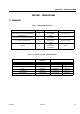
SECTION 1 - SPECIFICATIONS SECTION 1. SPECIFICATIONS 1.1 CAPACITIES Table 1-1. DRIBE HUB CAPACITIES TYPE DRIBE HUB SPEED MACHINE CAPACITIES BONFIGLIOLI 7C 00 1 G 40 HC0 5.25 065RT01P 3WH LZ 1V X14JH X14J-X390AJ 0,340 kg (0,75 lbs) BONFIGLIOLI 7C 00 1G 40 HC0 5.25 080RT01P 3WI1 LA 1V X17J X19J-X550AJ 0,340 kg (0,75 lbs) BONFIGLIOLI 7C 01 2 K A L 53 G018VP34 LA 2V X23J-X700AJ 0,620 kg (1,37 lbs) 2V X14JH X17J X14J-X390AJ X19J-X550AJ NO OIL EATON Table 1-2.
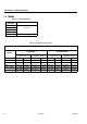
SECTION 1 - SPECIFICATIONS 1.2 TRACKS Table 1-3. Track Specifications MODEL MACHINE TRACK DIMENSIONS X14JH X14J-X390AJ 180x37x72 X17J X19J-X550AJ X23J-X700AJ 230x39x96 Table 1-4.
SECTION 1 - SPECIFICATIONS 1.3 ENGINE DATA NOTE: RPM Tolerances are ± 50. HONDA ENGINE GX270 - GX390 Table 1-5. SPECIFICATIONS HONDA ENGINE GX270-GX390 Model Description code Type GX270 GX390UT2 GCALK GCBCT 4 stroke, overhead valve, single cylinder, inclined by 25° Displacement 270 cm3 (16.5 cu–in) 389 cm3 (23.7 cu–in) Bore x stroke 77.0 x 58.0 mm (3.0 x 2.3 in) 88.0 x 64.0 mm (3.5 x 2.5 in) 6.7 kW (9 HP) / 3,600 min-1 (rpm) 8.7 kW (11.
SECTION 1 - SPECIFICATIONS HONDA ENGINE IGX440 Table 1-6. SPECIFICATIONS HONDA ENGINE iGX440 Model iGX440U Description code Type GCAWK 4-stroke, overhead camshaft, single cylinder, inclined by 15° Displacement 438 cm3 (26.7cu-in) Bore x stroke 88.0 x 72.1 mm (3.46 x 2.84 in) Maximum horsepower 11.2 kW (15.2 HP) / 3,600 min-1 (rpm) Recommended maximum operation bhp 8.0 kW (10.8 HP) / 3,600 min-1 (rpm) Maximum torque 29.8 N·m (3.
SECTION 1 - SPECIFICATIONS HATZ ENGINE 1B30 - 1B40 Table 1-7. SPECIFICATIONS HATZ ENGINE 1B30-1B40 Type 1B30 Design 1B40 Air-cooled four-stroke diesel engine Combustion system Direct injection Number of cylinders 1 1 80 / 69 mm 88 / 76 mm 347 cm3 462 cm3 Lubricating oil capacity without oil sump with oil sump 1.1 1) l, approx. 2.8 1) l, approx. 1.5 1) l, approx. 3.2 1) l, approx. Difference between “max” and “min” levels without oil sump with oil sump 0.5 1) l, approx. 1.8 1) l, approx.
SECTION 1 - SPECIFICATIONS 1.4 SPECIFICATIONS AND PERFORMANCE DATA Reach Specifications Table 1-9. Reach Specifications X14J X14J-H X17J X19J X23J Platform Height w 120 kg capacity 38' 7" (11.80 m) 39' 2" (11.90 m) 48' 5" (14.81 m) 54' 6" (16.67 m) 69' 2" (21.10 m) Platform Height w 200 kg capacity 33' 2" (10.15 m) 34'7" (10.58 m) 43' (13.12 m) 49' (14.96 m) 64' 6" (19.70 m) Horizontal Outreach (Std Platform w 120kg) 20' 5" (6.26 m) 21' 3" (6.50 m) 25' 1" (7.68 m) 19' 3" (5.
SECTION 1 - SPECIFICATIONS Table 1-10. Reach Specifications X390AJ Gasoline Engine X550AJ X700AJ Honda GX270 Honda iGX440 Honda iGX440 9 hp (6.7 kW) 15 hp (11.1 kW) 15 hp (11.1 kW) Hatz 1B30 Hatz 1B40 Perkins 402.05 7 hp (5.22 kW) 10 hp (7.46 kW) 14 hp (10.44 kW) 90Ah 48V Lithium-Ion 90Ah 48V Lithium-Ion 90Ah 70V Lithium-Ion 1.4 gal. (5.3 L) 1.5 gal. (5.9 L) 1.5 gal. (5.9 L) or Honda iGX390 13 hp (9.
SECTION 1 - SPECIFICATIONS Chassis Table 1-12. Chassis specifications X14J X14J-H X17J X19J X23J Gradeability 36% 33.5% 36% 38% 40% Maximum operating slope 10° 10° 11° 11° 13 Front 20° / Rear 20° Front 24.5° / Rear 18.5° Front 20° / Rear 21° Front 21° / Rear 21° Front 22° / Rear 25° Max. Approach / Depart angles Track size - McLaren low profile 1.24 m x 0.18 m 1.24 m x 0.18 m 1.24 m x 0.18 m 1.24 m x 0.18 m black rubber x 0.30 m x 0.30 m x 0.30 m x 0.
SECTION 1 - SPECIFICATIONS 1.5 FUNCTION SPEEDS Table 1-13.
SECTION 1 - SPECIFICATIONS 1.6 PRESSURE SETTINGS - PSI (BAR) Table 1-14. Pressure settings Model X14JH UNDERCARRIAGE Left and Right Control Valve Bar 175 PSI 2540 165 2400 160 2320 TOWER Control Valve X14J-X390AJ X17J X19J-X550AJ X23J-X700AJ Bar 180 PSI 2610 165 2400 180 2610 215 3120 185 2685 Table 1-15.
SECTION 1 - SPECIFICATIONS 1.7 SERIAL NUMBER LOCATION A serial number plate is affixed on to the frame or the basket A frame. The following illustrations showing the position on each model. Figure 1-1. Plate Figure 1-3. Plate location on X14J-X390AJ Figure 1-2. Plate location on X17J 3121448 Figure 1-4.
SECTION 1 - SPECIFICATIONS Figure 1-5.
SECTION 1 - SPECIFICATIONS NOTES: 3121448 – JLG Lift – 1-13
SECTION 2 - GENERAL SECTION 2. GENERAL 2.1 MACHINE PREPARATION, INSPECTION, AND MAINTENANCE General This section provides the necessary information needed by those personnel that are responsible to place the machine in operation readiness and maintain its safe operating condition. For maximum service life and safe operation, ensure that all the necessary inspections and maintenance have been completed before placing the machine into service.
SECTION 2 - GENERAL Table 2-1. Inspection and Maintenance Primary Responsibility Service Qualification Prior to use each day; or At each Operator change. User or Operator User or Operator Operator and Safety Manual Pre-Delivery Inspection Prior to each sale, lease, or rental delivery. Owner, Dealer, or User Qualified JLG Mechanic Service and Maintenance Manual and applicable JLG inspection form.
SECTION 2 - GENERAL Component Disassembly and Reassembly Hydraulic Lines and Electrical Wiring When disassembling or reassembling a component, complete the procedural steps in sequence. Do not partially disassemble or assemble one part, then start on another. Always recheck your work to assure that nothing has been overlooked. Do not make any adjustments, other than those recommended, without obtaining proper approval.
SECTION 2 - GENERAL fied intervals required in the Lubrication Chart in Section 1. Always examine filters for evidence of metal particles. 3. Cloudy oils indicate a high moisture content which permits organic growth, resulting in oxidation or corrosion. If this condition occurs, the system must be drained, flushed, and refilled with clean oil. 4. It is not advisable to mix oils of different brands or types, as they may not contain the same required additives or be of comparable viscosities.
SECTION 2 - GENERAL 2.5 PINS AND COMPOSITE BEARING REPAIR GUIDELINES Filament wound bearings. 1. Pinned joints should be disassembled inspected if the following occurs: and a. Excessive sloppiness in joints. b. Noise originating from the joint during operation. 2. Filament wound bearings should be replaced if any of the following is observed: a. Frayed or separated fibers on the liner surface. b. Cracked or damaged liner backing. 2.
SECTION 2 - GENERAL NOTES: 2-6 – JLG Lift – 3121448
SECTION 3 - CHASSIS & TURNTABLE SECTION 3. CHASSIS & TURNTABLE 3.1 RUBBER TRACK MAINTENANCE 4. When correct track tension has been obtained, turn valve (1) in a clockwise direction and tighten it. Clean all traces of grease. Checking track tension Stop the machine on solid, level land. Lift the machine into safe conditions and place stable supports under the undercarriage frame for total support.
SECTION 3 - CHASSIS & TURNTABLE Checking The Rubber Tracks 3. Separation of the metal cores g PATTERN WORN PARTS Figure 3-4. SPROCKET STEEL WIRE HOLE WHEEL SIDE METAL CORE a. The metal core acts as a type of adhesive of the rubber between the core itself and the steel ropes. Separation may be caused by excessive tension as breakage of the ropes for the following reasons: Figure 3-3. Rubber Track Structure The structure of the rubber track is illustrated in Figure 3-3.
SECTION 3 - CHASSIS & TURNTABLE 4. If the grease does not start to drain, turn the track slowly. and progressive damage, they allow the track to continue working. The development of the damage indicated in point 3 leads to the exposure of the metal cores and if they are exposed for more than half of the track circumference, it means that it is time to replace them. It can however still be used. 5. Insert three steel pipes (4) inside the track in the space between the rollers.
SECTION 3 - CHASSIS & TURNTABLE 7 52 02 02 BH 19 8 Figure 3-8. Checking tightness of nuts and bolts Depending on the use of the platform, it is indispensable to check the parts and the nuts and bolts in general, which are subject to loosening. Pay particular attention to the frame components, such as track-tensioning wheels, traversing geared motors, driving wheels and guide rollers. Check that they are tightened sufficiently as indicated in the following table.
3121448 – JLG Lift – Sq In 0,0524 0,0580 0,0775 0,0878 0,1063 0,1187 0,1419 0,1599 0,1820 0,2030 0,2260 0,2560 0,3340 0,3730 0,4620 0,5090 0,6060 0,6630 0,7630 0,8560 0,9690 1,0730 1,1550 1,3150 1,4050 1,5800 In 0,3125 0,3125 0,3750 0,3750 0,4375 0,4375 0,5000 0,5000 0,5625 0,5625 0,6250 0,6250 0,7500 0,7500 0,8750 0,8750 1,0000 1,0000 1,1250 1,1250 1,2500 1,2500 1,3750 1,3750 1,5000 1,5000 Sq In 0,00604 0,00661 0,00909 0,01015 0,01400 0,01474 0,01750 0,02000 0,0318 0,0364 0,1120 0,1120 0,1380 0,1380
3-6 – JLG Lift – Sq In 0,0524 0,0580 0,0775 0,0878 0,1063 0,1187 0,1419 0,1599 0,1820 0,2030 0,2260 0,2560 0,3340 0,3730 0,4620 0,5090 0,6060 0,6630 0,7630 0,8560 0,9690 1,0730 1,1550 1,3150 1,4050 1,5800 In 0,3125 0,3125 0,3750 0,3750 0,4375 0,4375 0,5000 0,5000 0,5625 0,5625 0,6250 0,6250 0,7500 0,7500 0,8750 0,8750 1,0000 1,0000 1,1250 1,1250 1,2500 1,2500 1,3750 1,3750 1,5000 1,5000 Sq In 0,00604 0,00661 0,00909 0,01015 0,01400 0,01474 0,01750 0,02000 0,0318 0,0364 0,1120 0,1120 0,1380 0,1380 0,16
3121448 8,78 28,90 36,60 1 1,25 1,5 1,75 2 2 2,5 2,5 2,5 3 3 3,5 3,5 4 4,5 7 8 10 – JLG Lift – 12 14 16 18 20 22 24 27 30 33 36 42 487,0 355,5 302,0 244,0 199,5 153,5 132,0 106,5 83,5 50,0 68,3 36,7 25,2 15,9 12,6 8,74 6,18 3,82 2,95 164 4090 2560 1990 1460 1080 737 581 426 3070 1920 1490 1100 810 553 436 320 226 219 301 105 66 38 19 13 7,9 4,6 2,3 1,6 1,0 [N.m] Torque (Lub) 140 88 50 26 18 11 6,2 3,1 2,1 1,3 [N.
SECTION 3 - CHASSIS & TURNTABLE 3.2 UNDERCARRIGE COMPONENTS Replacement wheel drive and Motor a. Stabilize the machine on level ground. b. Fully extend the undercarriage. c. Remove the tracks (see paragraph 3.1). 11 d. Remove the key ignition, and a tag with warning do not start the machine. 10 12 1 11 9 8 12 6 7 Figure 3-12. Figure 3-14. 1. Stabilize the machine on level ground. Replacement roller lower wheel and tracks adjuster 2. Fully extend the undercarriage. 3.
SECTION 3 - CHASSIS & TURNTABLE Table 3-1. Final drive torque valves n.
SECTION 3 - CHASSIS & TURNTABLE 3.3 CYLINDERS AND ENLARGEMENT GUIDE 19. Using a suitable lifting (minimum 200kg) to remove the track frame. 5 6 3 4 Figure 3-18. 20. Remove screw and nut 3-6. Figure 3-15. 21. Remove the pin 4. 12. Stabilize the machine on level surface. 13. Extend the undercarriage. 22. Disconnect, tag and plug the hydraulic hoses from the cylinder extension. 14. Engine and key off. 23. Remove the cylinder. 15.
SECTION 3 - CHASSIS & TURNTABLE 3.4 DRIVE GEAR MOTOR TABLE Table 3-2. SECTION TYPE SPEED 3.5 BONFIGLIOLI 7C 00 1 G 40 HC0 5.25 065RT01P 3WH LZ 1V X14JH X14J-X390AJ 065 3.5 BONFIGLIOLI 7C 00 1G 40 HC0 5.25 080RT01P 3WI1 LA 1V X17J X19J-X550AJ 080 3.6 BONFIGLIOLI 7C 01 2 K A L 53 G018VP34 LA 2V X23J-X700AJ 3.
SECTION 3 - CHASSIS & TURNTABLE 3.5 TRACK DRIVE - BONFIGLIOLI (MT700C077) Table 3-3. TYPE SPEED BONFIGLIOLI 7C 00 1 G 40 HC0 5.25 065RT01P 3WH LZ 1V BONFIGLIOLI 7C 00 1G 40 HC0 5.25 080RT01P 3WI1 LA 1V MACHINE MOTOR X14JH X14J-X390AJ 065 X17J -X500AJ X19J-X550AJ 080 INFORMATION FOR ALL ENQUIRIES REGARDING GENERAL INFORMATION ON THE PRODUCT, SPARE PARTS, ASSISTANCE ETC, ALWAYS GIVE THE IDENTIFICATION DATA STAMPED ON THE ID PLATE.
SECTION 3 - CHASSIS & TURNTABLE TECHNICAL INFORMATIONS PRODUCT DESCRIPTION The TRASMITAL BONFIGLIOLI gear motors of the series described in this manual are designed and built for application as track drive for crawled machines equipped with open loop hydraulic circuit.
SECTION 3 - CHASSIS & TURNTABLE An important piece of advice given is “to perfectly“ design the main hydraulic system. The illustrations show the parts and the main functions of the gearmotor. Figure 3-22.
SECTION 3 - CHASSIS & TURNTABLE Figure 3-23.
SECTION 3 - CHASSIS & TURNTABLE INSTALLATION INFORMATIONS MOUNTING THE PRODUCT TO THE MACHINE 3. Move the gearmotor in the mounting area applying lifting methods. INSTALLATION PROCEDURE 4. Install the motor gearbox connecting it to the machine frame and to the sprocket using all screws as the thread holes on to the flanges. Lock the screws with the tightening torque shown in the following scheme. Before proceeding with installation, follow the instructions given below. 1.
SECTION 3 - CHASSIS & TURNTABLE FILLING-UP THE GEARBOX WITH LUBRICATING OIL Before starting up the motor gearbox, check the level of lubricating oil in the gearbox. Check that the gearbox axis is horizontal. If necessary, refill with lubricant oil. INFORMATION This procedure is undertaken following the indications given below. D O N O T M I X T O G E T H E R O I L S O F D I F F E RE N T BRANDS OR CHARACTERISTICS. Figure 3-27.
SECTION 3 - CHASSIS & TURNTABLE 8. Rotate the gearbox housing, so that the plug (1) is on the top of the cover. CHARACTERISTICS OF THE HYDRAULIC SYSTEM 9. Unscrew the two plugs (1-2) and fill from the upper hole until the oil flows out from the hole (2). The oil in the hydraulic system (which also lubricates the hydraulic motor) must reflect the ISO VG 46 characteristics.
SECTION 3 - CHASSIS & TURNTABLE FIRST START UP AND RUNNING IN MAINTENANCE INFORMATIONS In this first stage it is advised to follow the measures given below. PERIODIC MAINTENANCE 11. Bleed air from every part of the hydraulic circuit and add oil in the tank if necessary. INFORMATION THE PRESENCE OF RESIDUAL AIR IN THE HYDRAULIC CIRCUIT WILL MANIFEST ITSELF WITH THE PRESENCE OF FOAM IN THE TANK AND WILL LEAD TO A JERKING OF THE MOTOR AS WELL AS EXCESSIVE NOISE COMING FROM THE MOTOR AND THE VALVES. 12.
SECTION 3 - CHASSIS & TURNTABLE TROUBLESHOOTING The following table is a guideline to identify the troubles in the track drive. Table 3-5.
SECTION 3 - CHASSIS & TURNTABLE MOTORGEARBOX DISASSEMBLY In the case that it was necessary to undergo a (partial or total) revision, it will be necessary to dismount the gearmotor from the machine. As this is known as an out of the ordinary maintenance procedure, it is important that only personnel with specific skills and experience undertake it. It is also important that this procedure is undertaken in a workshop that is adequately tooled.
SECTION 3 - CHASSIS & TURNTABLE Figure 3-29.
SECTION 3 - CHASSIS & TURNTABLE Figure 3-30.
SECTION 3 - CHASSIS & TURNTABLE Figure 3-31.
SECTION 3 - CHASSIS & TURNTABLE Figure 3-32.
SECTION 3 - CHASSIS & TURNTABLE DISASSEMBLING METHOD Initial inspection can be made without disassembling the sprocket and the track drive from the machine.Before track drive disassembling, make sure that the oil is discharge. 3. Remove the O-ring seal (28) from the hydraulic motor seat. GEARBOX DISASSEMBLY 1. Unscrew the 4 socket head screws M8x45 (29), grade 12.9, and the 2 socket head screws M8x75 (54), grade 12.9, which fix the hydraulic motor to the gearbox. Figure 3-35. 4.
SECTION 3 - CHASSIS & TURNTABLE 5. Mark the position of the springs (27) as a reference for the reassembling step. GEROUSLY DURING THE DISASSEMBLING PROCEDUREINDICATED AT THE FOLLOWING STEP. Figure 3-39. 7. Inflate compressed air into the brake port until the brake piston (26) comes out. Figure 3-37. 6. Take out the springs (27). Figure 3-40. Figure 3-38. 8. Remove the brake piston (26). TIGHTEN NOS.
SECTION 3 - CHASSIS & TURNTABLE 9. Remove the O-ring seals (23-24) and the backup rings (22-25) from their seats in the flanged hub (15). 12. Take out the brake disc unit (20-21). Figure 3-45. Figure 3-42. 13. Take out the sun gear (17). 10. Take out the brake shaft (19). Figure 3-46. Figure 3-43. 11. Remove the circlip (18) from the brake shaft (19). 14. Turn the gearbox upside down and by using a screwdriver remove the circlip (1). Figure 3-44. 3-28 Figure 3-47.
SECTION 3 - CHASSIS & TURNTABLE 15. Place the wrench into the plug (2), jack and remove the end cover (4). 17. Remove the O-ring seal (5) from its seat in the gearbox housing (9). Figure 3-50. Figure 3-48. 16. By using a puller remove the pad (3) from the end cover (4). 18. By using pliers remove the circlips (6) from the planet assemblies (7). INFORMATION THE ABOVE OPERATION MUST BE EXECUTE ONLY IN CASE OF REPLACEMENT OF THE PAD. Figure 3-51. 19. By using a puller remove the planet assemblies (7).
SECTION 3 - CHASSIS & TURNTABLE 20. By using pliers remove the circlip (8) from its seat in the flanged hub (15). 21. Fix the equipment (ATZ.05.014.0) at the bearing (14). Figure 3-53. Figure 3-55. NOTE: In order to proceed with the gearbox disassembly, it is now necessary to remove it from the ma-chine and bring it to a properly equipped workshop. By using a puller, push on the metal stopper and remove the flanged hub (15) from the gearbox housing (9). 22.
SECTION 3 - CHASSIS & TURNTABLE 23. By using a screwdriver remove the half seal (14) from the flanged hub (15). 25. By using pliers remove the circlip (12) from its seat in the gearbox housing (9). Figure 3-57. 24. Remove the O-Ring seal (13) from its seat in the gearbox housing (9). Figure 3-59. 26. By using a puller, push on the metal stopper and remove in the same time the spacer (11) and the bearing (10) from the gearbox housing (9). Figure 3-58. Figure 3-60.
SECTION 3 - CHASSIS & TURNTABLE HYDRAULIC MOTOR DISASSEMBLY head screws M8 (43), grade 10.9, and remove the washers (42). 1. Unscrew the 2 socket head screws M5x40 (55) grade 10.9, which fix the counterbalance valve to the hydraulic motor. Figure 3-63. 4. Remove the motor cover (41). Figure 3-61. 2. Remove the counterbalance valve. Figure 3-64. 5. Remove the O-ring seal (38) from the motor cover (41). Figure 3-62. 3. Place the hydraulic motor on the support with the output side downwards.
SECTION 3 - CHASSIS & TURNTABLE 6. Remove the roller gerotor (40) together with the distibutor plate (39) to prevent the parts from falling out (rolls ans stator). 8. Remove the O-ring seal (38) from the motor housing (36a). Figure 3-68. Figure 3-66. 9. Remove the 2 ball. 7. Split the distributor plate (39) from the roller gerotor (40). From this one, remove the O-ring seal (38) from its seat. Figure 3-69. 10. Rimove the Seeger (30). Figure 3-67. Figure 3-70.
SECTION 3 - CHASSIS & TURNTABLE 11. Reverse the hydraulic motor body (36a) and hammer on the shaft 36b. 14. Remove the joint float (37) and remove the tree distributor (36b). Figure 3-74. Figure 3-71. 15. Decompose the cover (31), the thrust bearing shim (32) and the cover (31). 12. You must present the case. Figure 3-75. 16. Remove O-Ring (35) from cover (31). Figure 3-72. 13. Remove distributor shaft bearing (34) the fifth wheel shim (32) and the cover (31) . Figure 3-76. Figure 3-73.
SECTION 3 - CHASSIS & TURNTABLE COUNTERBALANCE VALVE DISASSEMBLY 3. Remove the O-Ring seals (45) from valve plugs (48). 1. Remove the O-Ring seals (49-50) from their seat in the valve housing (56). Figure 3-79. 4. Remove the springs (46) from their seats in the valve housing (56). Figure 3-77. 2. Fix the valve (56) without damaging the motor matching surface and uscrew the valve plugs (48). Figure 3-80. Figure 3-78.
SECTION 3 - CHASSIS & TURNTABLE 5. Remove the spool (53) by sliding it and remove the spring seat (47). Figure 3-83. Figure 3-81. 6. Remove the other spring seat (47). EVALUATION OF THE PIECES TO BE REPLACED The pieces that are subject to general wear and tear are the following. Gears Bearings All the seals Replace the used or irregular parts respecting the following steps. 1. Accurately remove dirt, and in particular properly clean the seals, bearings and locking rings seating. 2.
SECTION 3 - CHASSIS & TURNTABLE Reassembling method 3. Insert the springs (46) into the valve housing (56). COUNTERBALANCE VALVE REASSEMBLY 1. Slide the spool (53) into the valve housing (56). Figure 3-86. 4. Assemble the O-ring seals (45) on the valve plugs (48). Figure 3-84. 2. Insert the spring seats (47) into the valve housing (56). Figure 3-87. 5. Insert the valve plugs (48) and tighten them by a torque wrench at 100 Nm torque. Figure 3-85. Figure 3-88.
SECTION 3 - CHASSIS & TURNTABLE 6. Assemble the O-ring seals (49-50) in their seats in the valve housing (56). INFORMATION BE CAREFUL TO THE CORRECT DIRECTION OF ASSEMBLY. Figure 3-89. Figure 3-91. HYDRAULIC MOTOR REASSEMBLY 7. Place the motor housing (36a) on the support with the output side upwards. If removed, apply Loctite 542 on the plug (44) and tighten, by a torque wrench, at 50 Nm torque. 9. Apply a slight coat of grease all over the internal diameter.
SECTION 3 - CHASSIS & TURNTABLE 12. Apply a slight coat of grease on the O-ring seat on the motor housing (36a). INFORMATION BE CAREFUL TO THE CORRECT DIRECTION OF ASSEMBLY. Figure 3-95. Figure 3-93. 11. Insert the internal cover (31) sub assembly on the timing shaft (36b) being careful that the axial bearing (34) is properly placed on its seat. 13. Place the O-ring seal (35) into its seat in the motor housing (36a). Figure 3-96. Figure 3-94. 3121448 14.
SECTION 3 - CHASSIS & TURNTABLE BECAUSE OF THE VERY TIGHT CLEARANCE, CLEAN THE PARTS VERYWELL AND GUIDE THE SHAFT CAREFULLY INTO THE MOTOR HOUSING TO PREVENT IT FROM TILTING. ROTATE THE TIMING SHAFT (36B) UNTIL THE MARK IS PLACED ON THE MOTOR AXIS OF SYMMETRY, OIL PORT SIDE. Figure 3-97. Figure 3-99. 15. Insert the 6 socket head screws M6x12 (30), grade 8.8 and tighten by a torque wrench, at 10 Nm torque. 17. Apply a slight coat of grease on the O-ring seat on the motor housing (36a). Figure 3-100.
SECTION 3 - CHASSIS & TURNTABLE 18. Place the O-ring seal (38) into its seat. 21. Apply a slight coat of grease on the O-ring seat of the gerotor (40). Figure 3-101. 19. Place the distributor plate (39) onto the motor housing (36a) with the holes lined up. Figure 3-104. 22. Place the O-ring seal (38) into its seat. Figure 3-102. Figure 3-105. 20. Insert the cardan shaft (37). FIND THE AXIS OF SYMMETRY OF THE ROLLER GEROTOR (40) AND DEFINE THE POSITION WHERE A TOOTH OF THE ROTOR IS Figure 3-103.
SECTION 3 - CHASSIS & TURNTABLE THE MOST INSIDE TWO ROLLS (CALLED “MINIMUM VOLUME CHAMBER”). 24. Apply a slight coat of grease on the O-ring seat of the motor cover (41). Figure 3-108. Figure 3-106. 23. Place the roller gerotor (40) on the cardan shaft with theO-ring seal (38) faced down towards the distributor plate. 25. Place the O-ring seal (38) into its seat.
SECTION 3 - CHASSIS & TURNTABLE 27. Place the 7 washers (42) and insert the 7 exagonal head screws M8 (43), grade 10.9. 29. Place the counterbalance valve on the hydraulic motor. Figure 3-113. Figure 3-111. 28. Tighten the 7 exagonal head screws M8 (43) grade 12.9, by a torque wrench at 25 Nm torque. INFORMATION 30. Fix the counterbalance valve to the hydraulic motor by 2 flathead screws M5x45 (55) grade 10.9, tightened by a torque wrench at 7,5 Nm torque. THIS IS ONLY A FIRST STEP TIGHTENING.
SECTION 3 - CHASSIS & TURNTABLE 31. Connect P1 and P2 ports to an hydraulic power unit with 10 l/min oil flow and run the motor unloaded. 32. Tighten the screw (43) by a torque wrench, at 38 Nm torque. Figure 3-117. Figure 3-115. INFORMATION WHILE THE MOTOR IS RUNNING UNLOADED, COMPLETE THE TIGHTENING OF THE HEXAGONAL HEAD SCREWS M8 (43), GRADE 10.9 FOLLOWING THE INDICATED ORDER. REASSEMBLY OF THE GEARBOX 1. Place the bearing (10) inside the gearbox housing (9). Figure 3-116. Figure 3-118.
SECTION 3 - CHASSIS & TURNTABLE 2. By using a press and a metal stopper, push the bearing (10) against the shoulder on the gearbox housing (9) until assembly is complete. Figure 3-121. Figure 3-119. 3. Assemble the spacer (11) on the gearbox housing (9). 5. Assemble the O-ring seal (13) into its seat in the gearbox housing (9). Figure 3-122. Figure 3-120. 3121448 4. By using pliers fit the circlip (12) into its seat in the gearbox housing (9).
SECTION 3 - CHASSIS & TURNTABLE Make ready of the lifetime seal: PLACE THE BEARING (14) IN THE GEARBOX HOUSING (9) WITH THE LAPPED SIDE UPWARDS. Carefully clean the seats ("A" and "B") using, if necessary, metal brushes or solvent (surfaces in contact with or ("C") must be perfectly clean and dry). Make sure that sealing surfaces "D" of metal rings "E" are free from scratches, dinges or foreign substances; metal ring surfaces must be perfectly clean and dry.
SECTION 3 - CHASSIS & TURNTABLE 8. By means of the tool (ATZ.04.008.0), carry out the assembly of the half seal (14) on the flanged hub (15). 10. Place the flanged hub (15) inside the gearbox housing (9). Figure 3-129. Figure 3-127. 9. Clean carefully the metallic faces of the lifetime seal (14), and Lube them with a thin oil film. 11. By using a press and a metal stopper push the flanged hub (15) against the gearbox housing shoulder (9) until assembly of the unit is complete. Figure 3-128.
SECTION 3 - CHASSIS & TURNTABLE 12. By using pliers, place the circlip (8) into its seat in the flanged hub (15). 14. By using a rubber hammer and a stopper, push the planet assemblies (7) against the flanged hub pin shoulders (15). Figure 3-131. Figure 3-133. 13. Place correctly the planet assemblies (7) on the flanged hub (15). 15. By using pliers, assemble the circlips (6) in the flanged hub pin seats (15). Figure 3-132. Figure 3-134.
SECTION 3 - CHASSIS & TURNTABLE 16. Fit the O-ring seal (5) into its seat in the gearbox housing (9). 19. By using pliers, place the circlip (1) into its seat in the gearbox housing (9). Figure 3-135. 17. Place the pad (3) on the end cover (4) and by using a puller push it against the shoulder untill assembling is complete. Figure 3-138. 20. Turn the gearbox upside down and insert the sun gear (17). Figure 3-139. Figure 3-136. 18. Place the end cover (4) on the gearbox housing (9). 21.
SECTION 3 - CHASSIS & TURNTABLE 22. Assemble the brake shaft (19). bronze discs and 8 steel discs have been assembled. Figure 3-141. 23. Assemble the brake discs package according to the following order: firstly, insert one steel disc with external teeth (21). Figure 3-143. 25. Apply in the seals' seats, inside the flanged hub (15) a thin oil film and assemble the O-ring seals (23-24) and the back-rings (22-25). Figure 3-142. Figure 3-144. 24.
SECTION 3 - CHASSIS & TURNTABLE ACCORDING THE MUTUAL POSITION AS SHOWN IN THE SCHEME. 28. Insert the springs (27) into the holes of the brake piston (26) marked previously. Figure 3-145. 26. Insert the brake piston (26) inside the flanged hub (15), being careful not to damage the seals already fitted. Figure 3-148. 29. Assemble the O-ring seal (16) in the brake port seat on the flanged hub (15). Figure 3-149. Figure 3-146. 27.
SECTION 3 - CHASSIS & TURNTABLE socket head screws M8x75 (54) grade 12.9, tightened by a torque wrench at 42 Nm torque. Figure 3-150. 30. Assemble the O-ring seal (28) into the hydraulic motor seat. Figure 3-153. 33. Fill the gearbox with the lubricant oil as shown in section 3.4. Insert the washers and the plugs (2) into the oil draing-filling holes of the end cover (4).Tighten the plugs by a torque wrench at 10±2 Nm torque. Figure 3-151. 31. Place the hydraulic motor on the flanged hub (15).
SECTION 3 - CHASSIS & TURNTABLE 3.6 TRACK DRIVE - BONFIGLIOLI (2T701C2K042002) TYPE SPEED BONFIGLIOLI 7C 01 2 K A L 53 G018VP34 LA 2V MACHINE MOTOR X23J-X700AJ Product Identification The identification data of the unit are shown on a name plates put on it. INFORMATION FOR ALL ENQUIRIES REGARDING GENERAL INFORMATION ON THE PRODUCT, SPARE PARTS, ASSISTANCE ETC, ALWAYS GIVE THE IDENTIFICATION DATA STAMPED ON THE ID PLATE. Figure 3-155.
SECTION 3 - CHASSIS & TURNTABLE TECHNICAL INFORMATION PRODUCT DESCRIPTION The BONFIGLIOLI TRASMITAL motor gearboxes of the series described in this manual are designed and built for application as track drive for crawled machines equipped with open loop hydraulic circuit. The track drive functional scheme shown in the sketch below.
SECTION 3 - CHASSIS & TURNTABLE An important piece of advice given is “to perfectly” design the main hydraulic system. The illustrations show the parts and the main functions of the gearmotor.
SECTION 3 - CHASSIS & TURNTABLE Figure 3-157.
SECTION 3 - CHASSIS & TURNTABLE INSTALLATION INFORMATION Direction of rotation INSTALLATION PROCEDURE Oil port inlet Before proceeding with installation, follow the instructions given below. • Properly clean the product by removing packaging and all remains of protection padding. Oil port outlet Direction of rotation (view from motor) P1 P2 Clockwise P2 P1 Counterclockwise • Prepare the parts to be coupled using the installation drawing as a guide.
SECTION 3 - CHASSIS & TURNTABLE Installation of the track drive on the machine Sprocket fixing to the track drive 10. Clean the mating surfaces from oils or paint and assemble the sprocket to the gearmotor. INFORMATION THE ENTIRE INSTALLATION PROCESS MUST BE PLANNED AS EARLY AS THE GENERAL DESIGN PHASE OF THE MACHINE. THE PERSON AUTHORISED TO DO THE WORK MUST, IF NECESSARY, SET OUT A SAFETY PLAN TO PROTECT THE HEALTH AND SAFETY OF ALL PERSONS DIRECTLY INVOLVED AND APPLY ALL APPLICABLE LEGISLATION. 11.
SECTION 3 - CHASSIS & TURNTABLE Hydraulic system connection The drain pressure must be lower than the values shown below. 12. Make sure that the entire hydraulic system meets the cleaning standard as given in level 9 according NAS 1638 or 22/18/15 ISO/DIS 4406. Motor drain pressure INFORMATION Continuous running Less than 1 bar CLEAN HOSES THOROUGHLY PRIOR TO CONNECTION AND REMOVE ANY INTERNAL OBSTRUCTIONS.
SECTION 3 - CHASSIS & TURNTABLE Gearbox lubrication The motor and the gearbox have separate lubrication. The gearbox is lubricated by oil splashing. The recommended oil type should have EP characteristics according to MIL-L-2105 C & API GL5. – For standard conditions, the recommended oil is: 1.Mineral oil SAE 80W/90. 2.Synthetic oil SAE 75W/90. INFORMATION – For heavy duty conditions (high loads, high duty cycles or high ambient temperatures), the recommended oil is: 1.Mineral oil SAE 85W/140.
SECTION 3 - CHASSIS & TURNTABLE Oil filling Characteristics of the hydraulic system BEFORE THE STARTING UP, CHECK THE LEVEL OF LUBRICATING OIL. IF NECESSARY, REFILL WITH LUBRICANT OIL. This procedure is undertaken following the indications given below. 1. Check that the gearbox axis is horizontal. Rotate the gearbox housing until the plug (1) is on the top on the vertical axis of the end cover. 2. Unscrew the oil plugs (1-2). 3. Fill from the hole (1) until the lubricant flows out from the hole (2). 4.
SECTION 3 - CHASSIS & TURNTABLE First start up and running in During the running-in stage follow the steps given below. In this first stage it is advised to follow the measures given below: 5. Check the correct revolution and direction of rotation. 1. Check the correctly lubrication of the unit. 6. Make sure that the functioning is regular and without any excessive noises and vibrations. 2. Fill the motor housing with hydraulic oil from the drain port (T1) (see the following picture). 3.
SECTION 3 - CHASSIS & TURNTABLE MAINTENANCE INFORMATION PERIODIC MAINTENANCE The gearmotor only requires the scheduled maintenance procedures set out by the manufacturer (see table below). Good maintenance will ensure an on going functioning in time as well as maximum reliability. Should irregularities in function arise, it will be necessary to consult the troubleshooting checklist to find the most adequate solution.
SECTION 3 - CHASSIS & TURNTABLE OIL DRAINING AND REPLACEMENT 11. Check that the gearbox axis is horizontal. Rotate the gearbox housing until the plug (1) is on the bottom of the vertical axis of the end cover. REMOVE THE OIL PLUGS WITH CARE. WHEN THE GEARBOX IS WARM, THE AIR INSIDE CAN BE PRESSURIZED AND THIS CAN CAUSE THEIR STRONGLY EXPULSION TOWARDS THE WORKER. 12. Unscrew the plugs (1-2) and let the oil flow in a large enough container; in order to facilitate the draining must be oil still warm. 13.
SECTION 3 - CHASSIS & TURNTABLE Troubleshooting The following table is a guideline to identify the troubles in the track drive.
SECTION 3 - CHASSIS & TURNTABLE DISASSEMBLY In the case that it was necessary to undergo a (partial or total) revision, it will be necessary to dismount the gearmotor from the machine. As this is known as an out of the ordinary maintenance procedure, it is important that only personnel with specific skills and experience undertake it. It is also important that this procedure is undertaken in a workshop that is adequately tooled.
SECTION 3 - CHASSIS & TURNTABLE 3121448 – JLG Lift – 3-67
SECTION 3 - CHASSIS & TURNTABLE 3-68 – JLG Lift – 3121448
SECTION 3 - CHASSIS & TURNTABLE Gearbox disassembly 3. Place the wrench into the plug (2), jack and remove the end cover (4). Initial inspection of the gears, can be made without disassembling the track and the track drive from the machine. INFORMATION THE COMPONENTS CAN BE VERY HEAVY AND LARGE DIMENSIONS: PAY ATTENTION DURING THE HANDLING. Before track drive disassembling, make sure that the oil is discharged according to instructions specified. 1. Unscrew the nos.
SECTION 3 - CHASSIS & TURNTABLE 9. By using pliers remove the circlip (11) from its seat in the hydraulic motor (17). 6. Remove the 1st reduction assembly (7). Figure 3-169. 7. By using pliers remove the circlips (8) from their seats placed in the hydraulic motor's pins (17). Figure 3-172. INFORMATION IN ORDER TO PROCEED WITH THE GEARBOX DISASSEMBLY, IT IS NOW NECESSARY TO REMOVE IT FROM THE MACHINE AND BRING IT TO A PROPERLY EQUIPPED WORKSHOP. 10.
SECTION 3 - CHASSIS & TURNTABLE 13. Remove the spacer (14) from the gearbox housing (10). INFORMATION IN CASE OF OIL LEAKAGES, IT MIGHT BE NECESSARY TO CHECK AND EVENTUALLY REPLACE THE LIFETIME SEALS (15), WHICH MEANS BOTH THE METAL RINGS PARTS AND THE O-RING SEALS. 11. Remove the 1st half seal (15) from the hydraulic motor (17). Figure 3-176. 14. By using pliers remove the circlip (13) from its seat in the gearbox housing (10). Figure 3-174. 12.
SECTION 3 - CHASSIS & TURNTABLE 16. By using a puller and a metal stopper, remove the bearing (12) from the gearbox housing (10). Hydraulic motor disassembly ANTICAVITATION VALVE DISASSEMBLY 18. Loosen the plugs (61) of the relief valves from the valve housing (66). Figure 3-179. 17. Remove the bearing (12) from the gearbox housing (10). 19. Unscrew the nos. 3 socket head screws M8x35 (68), grade 10.9, of the valve housing (66) by a male hex head wrench. Figure 3-180.
SECTION 3 - CHASSIS & TURNTABLE 20. Remove the valve housing (66). 23. Remove the O-ring seal (62) from each plug (61). 21. Remove the O-ring seals (67) from their seats in the valve housing (66). 24. By using pliers remove the nos. 2 springs (63). 22. Remove the plugs (61) of the anticavitation valve from the valve housing (66) previously loosened. 3121448 25. Remove the spool (65) from the anticavitation valve housing (66).
SECTION 3 - CHASSIS & TURNTABLE 26. Take out the nos. 2 spring seats (64) from the anticavitation spool (65). Disassembly of the base plate 27. View of the loose parts. 29. Loosen the plug (56) of the two speed control without remove it. 28. Loosen the counterbalance valve plugs (46) from the base plate (40) without remove them. 30. Unscrew the two speed control connector (57) from the base plate (40).
SECTION 3 - CHASSIS & TURNTABLE 31. Remove the O-ring seal (55) from its seat in the two speed control connector (57). 32. Unscrew the nos. 6 socket head screws M10x20 (58), grade 12.9, of the base plate (40) by a male hex head wrench. REMOVE CAREFULLY THE BASE PLATE (40) UNTIL PINS (39) ARE COMPLETELY OUT. 3121448 33. Take out the two speed spool (53). 34. Take out the spring (54). 35. View of the loose parts.
SECTION 3 - CHASSIS & TURNTABLE 39. Unscrew and remove the plugs (T11) from the base plate (T15). Disassembly of the counterbalance valve 36. Unscrew the counterbalance valve plugs (46), previously loosened, from the base plate (40). 40. Unscrew and remove the orifices (T12) from the base plate (T15). 37. Remove the valve plate (M21). 41. Unscrew the plugs (41) from the base plate (40). 38. By using a puller, remove the bearing (M22) from the base plate (T15).
SECTION 3 - CHASSIS & TURNTABLE 42. Remove the O-ring seals (42) from its seat in the plugs (41). 45. Remove the O-ring seals (45) from its seat in the plugs (46). Disassembly of the two speed control 46. Remove the nos. 2 springs (44). 43. Remove the plug (56) of the two speed control, previously loosened, from the base plate (40). 44. Remove the O-ring seal (55) from its seat in the plug (56). 3121448 47. Push right the counterbalance spool assy (47) to remove easily the spring seat (43).
SECTION 3 - CHASSIS & TURNTABLE 48. Take out the 1st spring seat (43) from the counterbalance spool assy (47). Disassembly of motor shaft and cylinder block 49. Remove the springs (M28) from the brake piston (M27). 50. Remove the O-ring seal (M6) from its seat in the flanged hub (M2). 51. Remove the cylinder block assy (M16).
SECTION 3 - CHASSIS & TURNTABLE 55. Take out the pistons (M11) from the retainer plate (M12). 52. Take out the spherical retainer plate holder (M13). 53. Take out the nos.3 pins (M15) from their seats in the cylinder block (M16). 54. Disassemble the pistons and the retainer plate (M11M12). 3121448 56. By using a puller, turn the screw until the brake piston (M27) comes out. 57. Remove the O-ring seals (M24-M25) and the backup rings (M23-M26) from their seats in the brake piston (M27).
SECTION 3 - CHASSIS & TURNTABLE 58. Take out the brake disc (M14). 61. Take out the nos.2 two speed control springs (M4) from their seats in the flanged hub (M2). 59. Remove the swash plate (M10) from the flenged hub (M2). 60. Take out the nos. 2 two speed control pistons (M5) from the flanged hub (M2). 3-80 62. Take out the nos.2 steel balls (M3) from their seats in the flanged hub (M2). 63. By using a puller, take out the motor shaft (M9) and the bearing (M8) from the the flanged hub (M2).
SECTION 3 - CHASSIS & TURNTABLE 64. By using a puller, take out the bearing (M8) from the motor shaft (M9). INFORMATION THE DISASSEMBLY ENDS WITH THE ABOVE OPERATION. ALL ITEMS ARE NOW AVAILABLE FOR THE NECESSARY INSPECTIONS. EVALUATION THAT PIECES TO REPLACE The pieces that are subject to general wear and tear are the following: Gears Pinion shaft Bearings Seals 65. By using a screwdriver remove the back-up ring (21) from its seat in the flanged hub (18).
SECTION 3 - CHASSIS & TURNTABLE Reassembling Method 3. By using the tool (ATZ.06.027) and a rubber hammer push the seal ring (M7) against the seat shoulder. REASSEMBLY OF MOTOR SHAFT AND CYLINDER BLOCK 1. Place the seal ring (M7) into its seat in the flanged hub (M2). 4. Assemble the nos.2 steel balls (M3) into their seats in the flanged hub (M2). 2. Apply a coat of grease on the seal ring (M7). 5. Assemble the nos.2 two speed springs (M4) into their seats in the flanged hub (M2).
SECTION 3 - CHASSIS & TURNTABLE 6. Assemble the nos.2 two speed pistons (M5) into their seats inside the flanged hub (M2). 9. Place the bearing-motor shaft sub-assembly (M8-M9) in the seat inside the flanged hub (M2). BE SURE THAT THE PISTONS CAN MOVE FREELY INTO THE SEATS. BE CAREFUL WHEN INSERTING THE SHAFT INSIDE THE MOTOR SEAL, THAT MUST BE GREASED. 7. Place the bearing (M8) on the motor shaft (M9). 10.
SECTION 3 - CHASSIS & TURNTABLE 11. Insert the swash plate (M10) inside the flanged hub (M2) being careful that spherical housings matches with the 2 steel balls (M3). 14. Piston orifice (M11) must be open and free of dust or dirt. 12. Assemble the nos.3 pins (M15) in their seats in the cylinder block (M16). 15. Assemble correctly the nos.9 pistons (M11) in the retainer plate (M12). 13. Assemble the spherical retainer holder (M13) on the cylinder block (M16). 16.
SECTION 3 - CHASSIS & TURNTABLE 17. Insert the brake disc (M14) in the cylinder block (M16). 20. Assemble the O-ring seals (M25-M24) into its seat in the brake piston (M27). Assemble the backup ring (M23) into its seat as shown on the sketch below. 18. Assemble the cylinder block sub assembly (M16) into the flanged hub (M2) on the motor shaft spline (M9). INFORMATION THE O-RING (A) AND A THE BACKUP (B) RING MUST BE FITTED IN THE SEAT ACCORDING THE MUTUAL POSITION AS SHOWN IN THE SCHEME. 19.
SECTION 3 - CHASSIS & TURNTABLE 21. Insert the brake piston (M27) inside the flanged hub (M2), being careful not to damage the seals already fitted. Reassembly of the base plate 1. Insert the orifices (51) in the base plate (40) and tighten by a torque wrench at 2,5 ± 0,5 Nm torque. 22. Assemble the O-ring seal (M6) into its seat in the flanged hub (M2). 2. Seal the thread of the plugs (52) by "Teflon" tape. INFORMATION BE SURE THAT THE TAPE IS CORRECTLY WINDED AROUND THE PLUGS (52). 23.
SECTION 3 - CHASSIS & TURNTABLE 3. Tighten the plugs (52) in the base plate (40) by a torque wrench at 5 ± 0,5 Nm torque. 6. Place the base plate (40) on the flanged hub (18). THE BASE PLATE IS CENTERED BY TWO PINS (39) AND THE SECOND SPEED OIL PASSAGES MUST MATCH TOGETHER. 4. Assemble the bearing (37) into its seat in the base plate (40). 7. Fix the base plate (40) to flanged hub (18) by using nos. 8 socket head screws M10x20 (58), grade 12.9, tightened by a torque wrench at 64 ± 5 Nm torque. 5.
SECTION 3 - CHASSIS & TURNTABLE 8. By using the stopper (6689962090) assemble the Oring (42) in its seat in the plug (41). 11. Tighten the plug (56) of the two speed control by a torque wrench at 54 ± 5 Nm torque. 9. Tighten the plug (41) by a torque wrench at 23,5 ± 1 Nm torque. 12. Insert the spring (54) in the two speed spool (53). Reassembly of the two speed control 13. Insert the two speed spool (53) in the base plate (40). 10.
SECTION 3 - CHASSIS & TURNTABLE Reassembly of the counterbalance valve 16. Insert the orifices (50) in the base plate (40) and tighten by a torque wrench at 2,5 ± 0,5 Nm torque. 14. By using the stopper (6689960740) assemble the Oring seal (55) in its seat in the two speed control connector (57). 15. Tighten the two speed control connector (57) by a torque wrench at 54 ± 5 Nm torque. 3121448 17. Slide the counterbalance valve spool (47) inside the base plate (40). 18. Insert the nos.
SECTION 3 - CHASSIS & TURNTABLE 19. Insert the nos. 2 springs (44) on the counterbalance valve spool (47). Anticavitation valve reassembly 20. Fit the O-ring seals (45) into their seats in the plug (46). 23. Insert the nos. 2 spring seats (64) on the spool (65). 21. Tighten the counterbalance valve plugs (46) by a torque wrench at 240 ± 5 Nm torque. 3-90 22. Assemble the spool (65) into the anticavitation valve housing (66). 24. Insert the nos. 2 springs (63) on the spool (65).
SECTION 3 - CHASSIS & TURNTABLE 25. By using the stopper (6689960740) assemble the Oring seals (62) in their seats in the plug (61). 26. Manually housing (66). screw the nos. 2 plugs (61) in the valve 27. Assemble the O-rings (67) into their seats in the valve housing (66). 3121448 28. Place the anticavitation valve (66) on the base plate (40). 29. Tighten the nos. 3 socket head screws M8x35 (68), grade 10.9, by a male hex head torque wrench at 37 ± 2 Nm torque. 30. Tighten the nos.
SECTION 3 - CHASSIS & TURNTABLE Gearbox reassembly 1. Place the bearing (12) inside the gearbox housing (10). 2. By using a press and a metal stopper, push the bearing (12) against the shoulder on the gearbox housing (10) until assembly is complete. Make ready of the lifetime seal: 1. Carefully clean the seats (A and B) using, if necessary, metallic brushes or solvent (surfaces in contact with or (C) must be perfectly clean and dry). 2.
SECTION 3 - CHASSIS & TURNTABLE INFORMATION CORRECT LIFETIME SEAL ASSEMBLY CHECK (15). 6. Assemble the 1st half seal (15) on the gearbox housing (10). 7. Assemble, by using the same tool (6689962100), the 2nd half seal (15) on the hydraulic motor (17). 3121448 8. Place the gearbox housing (10) putting the bearing (12) on the tool.
SECTION 3 - CHASSIS & TURNTABLE 9. Clean carefully the seal faces (15). 11. By using a press push the hydraulic motor (17) against the shoulder on the gearbox housing (10) until assembling of the unit is complete. APPLY A THIN OIL FILM ON THE ENTIRE METALLIC FACE OF ONE OR BOTH SEALS. OIL MUST NOT CONTACT SURFACES OTHER THAN THE SEALING FACES. 12. Turn the gearbox upside down and, by using pliers, place the circlip (11) into its seat in the hydraulic motor (17). 10.
SECTION 3 - CHASSIS & TURNTABLE 14. By using a rubber hammer and a metal stopper, push the planet assemblies of the 2nd reduction (9) against the hydraulic motor pin shoulders (17). 15. By using pliers, assemble the circlips (8) in the hydraulic motor pin seats (17). 16. Insert the 1st reduction assembly (7). 3121448 17. Insert the 1st reduction sun gear (6). 18. Fit the O-ring seal (5) into its seat in the gearbox housing (10). 19. Place the end cover (4) on the gearbox housing (10).
SECTION 3 - CHASSIS & TURNTABLE 20. By using a rubber hammer push the cover (4) against the gearbox housing shoulder (10). 22. Fill the gearbox with the lubricant oil. Insert the plugs (2) into the oil draining-filling holes of the end cover (4).Tighten the plugs by a torque wrench at 20 ÷ 30 Nm torque. 21. Fit the elastic ring (1) into its seat in the gearbox housing (10). FINAL TEST AND REINSTALLATION Check the product by remounting it to the machine. Check the function of the transmission.
SECTION 3 - CHASSIS & TURNTABLE 3.7 DRIVE HUB - EATON TYPE SPEED EATON 2V Spindle/wheel ass’y, Endcover ass’y MACHINE MOTOR X14JH X17J -X500AJ X14J-X390AJ X19J-X550AJ TR* series Orbit Motor Maintenance Manual INTRODUCTION This manual shows the way of disassembly and reassembly of TR* series ORBIT MOTOR . Please see the attached papers, Assembly drawing: TRCV49C2204-A (AZ7663B) Place the motor in a vise with the Geroler part. Clamp across the Endcover ass’y.
SECTION 3 - CHASSIS & TURNTABLE Remove the bolt (28) and Seal washer (30). Remove Valve plate (15) from the motor used Eyebolt and Screw driver. Remove the Geroler cover (16). Remove the drive (24). Remove the Geroler (1). 3-98 Remove the X-ring (26).
SECTION 3 - CHASSIS & TURNTABLE Reassenbly Remove the Valve ass’y (17). Check all mating surfaces. Replace any parts that have scratches or burrs that could cause leakage. Clean all metal parts in clean solvent. Blow-dry with air. Do not wipe dry with paper towel because lint or other matter can get in the hydraulic system and cause damage. Do not file or grind motor parts. Note: Please replace all old seals with new seals and lubricant all seals (prior to installation) with petroleum such as Vaseline.
SECTION 3 - CHASSIS & TURNTABLE Install the O-ring (31), (32). Pour the Gear oil into the Spindle / wheel ass’y (5). four holes Install the Endcover ass’y (36), and the bolts (29). Align four holes the wheel ass’y with the Endcover. Quantity TRC series: 100 cm3 TRB series: 55 cm3 Torque all 4 bolts alternately to 35 N-m. Gear oil: SHELL SPIRAX EP90 Install the Spacer (25) in the wheel ass’y.
SECTION 3 - CHASSIS & TURNTABLE Please mark to Valve ass’y(17). Pin (23) Install the X-ring (26) in the wheel ass’y. marking Install the Valve ass’y (17) in the wheel ass’y. Align the Pin (23) with the hole. Please attend these holes. Install the O-ring (31) in the valve plate (15).
SECTION 3 - CHASSIS & TURNTABLE Install the Valve plate (15) on the wheel ass’y. Please attend these holes and top of Star. Install the Drive (24) into the motor. Align the marked spline with the Valve’s marking. Align the marked spline with the above Valve plate holes. Install the O-ring (31) on the Valve plate (15). Install the Geroler (1) on the Valve plate (15). Align top of Star with marked Drive spline. Marked spline If you mistake the valve timing, motor turns in the opposite direction.
SECTION 3 - CHASSIS & TURNTABLE Please attend these holes. Please daub Loctit #242 with the Bolt (28) Install the Bolt (28) and Seal washer (30). Torque all 7 bolts alternately to 30 N-m Install the O-ring (31) on the Geroler cover (16). Install the Geroler cover (16) on the Geroler (1). Align holes with the Geroler’s holes. Please daub Loctit #242 with the Bolt (27), Install the Bolt (27). Torque all bolts alternately to 57 N-m TRC and TRB-B type series have ten bolts. TRB-C type has seven bolts.
SECTION 3 - CHASSIS & TURNTABLE Troubleshooting Condition Motor will not turn Cause No oil Correction Fill reservoir to proper oil level. Replace pump. Pomp broken Slow operation Erratic motor operation Motor turns in wrong direction Fluid leakage Relief valve stuck open or set too low Clean and free relief valve spool and Adjust to proper setting. Low oil viscosity Use proper viscosity oil. Worm pomp Repair or replace pump.
SECTION 3 - CHASSIS & TURNTABLE 3.8 SWING DRIVE (IMO) WD-L SERIES (LIGHT SERIES) The lighter series is designated as the WD-L series. The drive motor (hydraulic/electric) is optional. Additional optional components are potentiometers, permanent brake or front-end brake. TECHNICAL DATA – TYPE PLATE Figure 3-181. Type plate The type plate is on the housing and contains the following information: • Manufacturer • Drawing no./type Figure 3-182. Slew drive WD-L 1.
SECTION 3 - CHASSIS & TURNTABLE TRANSPORTING UNPACKED SLEW DRIVES Attachment: 1. Screw the 3 eye bolts into the 3 threads that are distributed uniformly on the circumference of the slew drive. SCREW IN THE EYE BOLTS TO THE FULL THREAD LENGTH! IMPROPERLY ATTACHED, UNSUITABLE, OR DAMAGED EYE BOLTS MAY CAUSE THE SLEW DRIVE TO FALL AND CAUSE LIFETHREATENING INJURIES. 2. Attach lifting gear to the eye bolts. 3. Start the transport. Figure 3-183.
SECTION 3 - CHASSIS & TURNTABLE INSTALLATION AND COMMISSIONING Preparation Cleaning the slew drive and mounting structure Wear the following additional protective equipment for cleaning work: Face protection to protect the eyes and face from solvents. Figure 3-185. Do not let cleaning agents get into the slew drive Chemical-resistant protective gloves to protect hands from aggressive substances. Check protective gloves for leaks prior to use.
SECTION 3 - CHASSIS & TURNTABLE DETERMINATION OF FLATNESS DEVIATION, AND PERPENDICULARITY DEVIATION AND DEFORMATION OF THE MOUNTING STRUCTURE IMPORTANT IF THERE ARE IMPERMISSIBLY HIGH DEVIATIONS IN FLATNESS AND PERPENDICULARITY IN THE MOUNTING STRUCTURE, THEN ROTATIONAL RESISTANCE OF THE SLEW DRIVE MAY SIGNIFICANTLY INCREASE AND DAMAGE THE ENTIRE SLEW DRIVE. IN THE WORST CASE THE SLEW DRIVE MAY BLOCK.
SECTION 3 - CHASSIS & TURNTABLE Figure 3-188. Permissible flatness deviation of the mounting structure δp = flatness deviation max. δp = maximum flatness deviation U = circumference • The maximum residual value for flatness deviation δp in the circumferential direction should only be reached once on half of the circumference. The gradient must look like a sinus curve that slowly rises or falls. Perpendicularity deviation Figure 3-189.
SECTION 3 - CHASSIS & TURNTABLE δw = perpendicularity deviation B = flange width • The permissible perpendicular deviation dw (tilting) is based on the actual flange width and should only be half of the values from the tables below. Figure 3-190. Drawing number The size of the slew drive (WD-H) or of the running circle diameter DL (WD-L/SP) is indicated in the drawing number at position (1) and is shown in all documents and the type plate.
SECTION 3 - CHASSIS & TURNTABLE Permissible flatness and perpendicularity deviation for series WD-L and SP slew drives ≥ 100 Running circle diameter [mm] Permissible flatness deviation including perpendicularity deviation per support surface ≥ 250 ≥ 500 ≥ 750 ≥ 1000 ≥ 1250 [mm] 0.04 0.06 0.08 0.09 0.10 0.11 [in] 0.0016 0.0024 0.0032 0.0036 0.0040 0.
SECTION 3 - CHASSIS & TURNTABLE Permissible deformation of the mounting structure, under maximum load for series WD-H slew drives ≥ 146 Size of the slew drive Permissible deformation of the mounting structure per support surface ≥ 220 ≥ 300 ≥ 373 ≥ 490 ≥ 625 [mm] 0.10 0.11 0.12 0.13 0.15 0.16 [in] 0.0040 0.0044 0.0048 0.0052 0.0059 0.0063 • Select bolt length to ensure that the minimum insertion depth is reached.
SECTION 3 - CHASSIS & TURNTABLE TIGHTENING BOLTS WITH A TORQUE WRENCH MOUNTING STRUCTURES WITH FRACTURE STRENGTH UNDER 500 N/MM² OR 72520 LBS/IN² ARE PROHIBITED. Normally the mounting bolts are adequately secured through correct pretension. ds = bolt diameter lk = grip length le = insertion depth Permissible interfacial pressure for various materials Material DO NOT USE IMPACT SCREWDRIVERS. USING AN IMPACT SCREWDRIVER MAY CAUSE IMPERMISSIBLE DEVIATIONS BETWEEN THE BOLT TIGHTENING FORCES.
SECTION 3 - CHASSIS & TURNTABLE 1) MA in accordance with VDI guideline 2230 (February 2003) for μK=0.08 and μG=0.12 2) F M in accordance with VDI guideline 2230 (February 2003) for μG=0.1 Tightening torques and bolt tightening forces for inch thread in accordance with ANSI B1.1 when using a torque wrench: Mounting bolt dimensions Tightening torque MA 1) Strength class 8 in Mounting pretension force FM 2) Strength class 8 in Nm ft-lbs kN lbs 0.1900 – 24 UNC 4.80 3.54 7.15 1607 0.
SECTION 3 - CHASSIS & TURNTABLE POSITIONING THE SLEW DRIVE MOUNT THE SLEW DRIVE IN UNSTRESSED STATE. 1. Determine the main load-carrying zone. The main load-carrying zone is that area of the slewing ring that is subject to the highest load, taking all aggressive forces and torques, and all occurring load cases into account.
SECTION 3 - CHASSIS & TURNTABLE DETERMINING THE TILTING CLEARANCE Table 3-7. Mounting bolt dimensions Mounting pretension force Tilting clearance increases as raceway system wear increases. To determine the increase in tilting clearance a basic measurement must be executed in installed status and prior to first-time operation. This is the only way to determine changes. FM 1) Strength class 10.
SECTION 3 - CHASSIS & TURNTABLE 7. Slew Drive 8. Lower mounting structure Procedure: Tilting clearance measurement 9. Switch off the system and safeguard it from being turned on again. 10. Permanently mark the measuring point in the main load direction on the housing and on the bearing ring. 11. Attach the dial gauge as shown in Fig. 24. 12. Apply defined tilt torque, at least 50% of max. operating load, in direction "A". 13. Set dial gauge to zero. 14. Apply defined tilt torque, at least 50% of max.
SECTION 3 - CHASSIS & TURNTABLE MAINTENANCE SCHEDULE Maintenance tasks are described in the sections below that are required for optimal and trouble-free operation. If increased wear is detected during regular inspections, then reduce the required maintenance intervals according to the actual indications of wear. If you have questions concerning maintenance tasks and intervals, please contact our customer service.
SECTION 3 - CHASSIS & TURNTABLE If comparable results are not available, the following table can be used as a guide value: Work conditions Lubricating interval To be executed by Approx. every 300 operating hours, at least every 6 months Specialist Approx.
SECTION 3 - CHASSIS & TURNTABLE CHECKING THE TILTING CLEARANCE MAINTENANCE TASKS INSPECTING THE MOUNTING BOLTS IMPORTANT TO COMPENSATE FOR SETTLING, THE BOLTS MUST BE RETIGHTENED WITH THE PRESCRIBED TIGHTENING TORQUE. RETIGHTENING MUST BE EXECUTED WITHOUT EXERTING ADDITIONAL EXTERNAL STRESS ON THE BOLTED UNION. Wear in the raceway system results in an increase in tilting clearance. Consequently it is necessary to check the tilting clearance in accordance with the maintenance intervals.
SECTION 3 - CHASSIS & TURNTABLE LUBRICATING THE SLEW DRIVE IMPORTANT REGULARLY LUBRICATE THE SLEW DRIVES TO PROLONG THEIR SERVICE LIFE AND ENSURE SAFE OPERATION. IMPORTANT ALWAYS USE THE LUBRICANTS SPECIFIED IN THE ORDER DRAWING. IF USING OTHER LUBRICANTS PAY ATTENTION TO THE RELATIVE MIX ABILITY OF THE SUBSTANCES. THE STANDARD LUBRICANTS USED ARE "R.TECC NORPLEX LKP2" FROM RHENUS, OR THE GREASE "OPTIMOL LONGTIME PD0" FROM CASTROL.
SECTION 3 - CHASSIS & TURNTABLE 3.9 HONDA ENGINE GX270 - GX390 SPECIFICATIONS SERIAL NUMBER LOCATION The engine serial number (1), type (2) and model (3) is stamped on thecrankcase.Refer to it when ordering parts or making technical inquiries.
SECTION 3 - CHASSIS & TURNTABLE ENGINE SPECIFICATIONS Table 3-9. Model GX270 GX390UT2 Description code GCBCT Type 4 stroke, overhead valve, single cylinder, inclined by 25° Displacement 270 cm3 (16.5 cu–in) 389 cm3 (23.7 cu–in) Bore x stroke 77.0 x 58.0 mm (3.0 x 2.3 in) 88.0 x 64.0 mm (3.5 x 2.5 in) Net power (SAE J1349)*1 6.7 kW (9 HP) / 3,600 min-1 (rpm) 8.7 kW (11.7 HP) / 3,600 min-1 (rpm) Continuous rated power 7.0 kW (9.4 HP) / 3,600 min-1 (rpm) Maximum net torque (SAE J1349)*1 19.
SECTION 3 - CHASSIS & TURNTABLE SERVICE INFORMATION TORQUE VALUES ENGINE TORQUE VALUES Item Crankcase cover bolt Cylinder head bolt Oil drain plug bolt Connecting rod bolt Rocker arm pivot bolt Rocker arm pivot adjusting nut Oil level switch nut Flywheel nut Fuel tank nut/bolt Fuel tank joint Air cleaner elbow nut Muffler nut Exhaust pipe nut Gear case cover bolt (With reduction) Primary drive gear bolt (With reduction) Engine stop switch tapping screw Recoil starter center screw Fuel strainer cup Tread
SECTION 3 - CHASSIS & TURNTABLE HARNESS AND TUBE ROUTING Connection of regulator/rectifier, charge/lamp coil, sub wire harness, and auto throttle solenoid are depending on the application of the engine, therefore, it does not indicate those parts in this manual.
SECTION 3 - CHASSIS & TURNTABLE ALL TYPE GOVERNOR ARM ENGINE WIRE HARNESS HIGH-TENSION CORD CARBURETOR INSULATOR CONTROL BASE ASSY. CYLINDER BARREL RIB CONTROL BASE ASSY.
SECTION 3 - CHASSIS & TURNTABLE WITH CHARGE COIL / LAMP COIL 10A CHARGE COIL TYPE: 12 V-50 W LAMP COIL TYPE: 18A CHARGE COIL TYPE: CORD CLAMPER CORD CLAMPER CORD GROMMET COIL CORD COIL CORD CORD GROMMET 1 A / 3 A CHARGE COIL TYPE: 12 V - 15 W / 12 V-25 W LAMP COIL TYPE: CORD CLAMPER CORD GROMMET COIL CORD 3121448 – JLG Lift – 3-127
SECTION 3 - CHASSIS & TURNTABLE MAINTENANCE SCHEDULE REGULAR SERVICE PERIOD (2) ITEM Perform at every indicated month or operating hour interval, whichever comes first. Engine oil Air cleaner Check level Change Check Clean Each use First month or 20 hrs. Every 3 months or 50 hrs. Every 6 months or 100 hrs.
SECTION 3 - CHASSIS & TURNTABLE ENGINE OIL LEVEL CHECK SAE 10W - 30 is recommended for general use. Other viscosities shown in the chart may be used when the average temperature in your area is within the recommended range. Place the engine on a level surface. Remove the oil filler cap (1), and wipe the oil level gauge (2) clean. Insert the oil filler cap without screwing it into the oil filler neck (3).
SECTION 3 - CHASSIS & TURNTABLE USED ENGINE OIL CONTAINS SUBSTANCES THAT HAVE BEEN IDENTIFIED AS CARCINOGENIC. IF REPEATEDLY LEFT IN CONTACT WITH THE SKIN FOR PROLONGED PERIODS, IT MAY CAUSE SKIN CANCER. WASH YOUR HANDS THOROUGHLY WITH SOAP AND WATER AS SOON AS POSSIBLE AFTER CONTACT WITH USED ENGINE OIL. Install a new drain plug washer (3) and tighten the drain plug bolt (2) to the specified torque. TORQUE:22.5 N·m (2.
SECTION 3 - CHASSIS & TURNTABLE INNER FILTER (PAPER) TYPE: Turn the fuel cock lever (1) to the OFF position. Tap the inner filter (1) lightly several times on a hard surface to remove excess dirt, or blow compressed air lightly (207 kPa (2.11 kgf/cm2, 30 psi) or less) through the paper filter from the inside out. Never try to brush the dirt off; brushing will force dirt into the fibers. Remove the sediment cup (2) and the O-ring (3).
SECTION 3 - CHASSIS & TURNTABLE SPARK PLUG CHECK/ADJUSTMENT 0.7 0.8 mm (0.028 0.031 in) IF THE ENGINE HAS BEEN RUNNING, THE ENGINE WILL BE VERY HOT. ALLOW IT TO COOL BEFORE PROCEEDING. Remove the spark plug cap, and then remove the spark plug (1) using a spark plug wrench (2). (2) (1) A LOOSE SPARK PLUG CAN BECOME VERY HOT AND CAN DAMAGE THE ENGINE. OVERTIGHTENING CAN DAMAGE THE THREADS IN THE CYLINDER BLOCK. INSTALL THE SPARK PLUG CAP SECURELY. Visually check the spark plug.
SECTION 3 - CHASSIS & TURNTABLE CLEANING A LOOSE SPARK PLUG CAN BECOME VERY HOT AND CAN DAMAGE THE ENGINE. OVERTIGHTENING CAN DAMAGE THE THREADS IN THE CYLINDER BLOCK. INSTALL THE SPARK PLUG CAP SECURELY. SPARK ARRESTER CLEANING BE CAREFUL TO AVOID DAMAGING THE SCREEN. Clean the carbon deposits from the spark arrester screen (1) with a wire brush (2).Check the spark arrester screen for damage. If the screen is damaged, replace the spark arrester.Install the spark arrester in the reverse order of removal.
SECTION 3 - CHASSIS & TURNTABLE VALVE CLEARANCE CHECK/ADJUSTMENT Insert a thickness gauge (1) between the valve rocker arm (2) and valve stem (3) to measure the valve clearance. Remove the head cover bolt (1), the head cover (2),and the head cover packing (3). VALVE CLEARANCE: IN: 0.15 ± 0.02 mm EX: 0.20 ± 0.02 mm (2) (3) If adjustment is necessary, proceed as follows. (3) (1) (1) Disconnect the spark plug cap from the spark plug.
SECTION 3 - CHASSIS & TURNTABLE COMBUSTION CHAMBER CLEANING (2) Remove the cylinder head (page 13-3). Clean any carbon deposits from the combustion chamber (1). (1) VALVE STEM (1) (2) To increase valve clearance: screw out. To decrease valve clearance: screw in.
SECTION 3 - CHASSIS & TURNTABLE FUEL TUBE CHECK FUEL TANK AND FILTER CLEANING GASOLINE IS HIGHLY FLAMMABLE AND EXPLOSIVE. YOU CAN BE BURNED OR SERIOUSLY INJURED WHEN HANDLING FUEL. GASOLINE IS HIGHLY FLAMMABLE AND EXPLOSIVE. YOU CAN BE BURNED OR SERIOUSLY INJURED WHEN HANDLING FUEL. •KEEP HEAT, SPARKS, AND FLAME AWAY. •HANDLE FUEL ONLY OUTDOORS. •WIPE UP SPILLS IMMEDIATELY. Check the fuel tube (1) for deterioration, cracks or signs of leakage. •KEEP HEAT, SPARKS, AND FLAME AWAY.
SECTION 3 - CHASSIS & TURNTABLE TROUBLESHOOTING BEFORE TROUBLESHOOTING •Use a known-good battery for troubleshooting. •Check that the connectors are connected securely. •Check for sufficient fresh fuel in the fuel tank. •Read the circuit tester's operation instructions carefully, and observe the instructions during inspection. •Disconnect the battery cable before continuity inspection.
SECTION 3 - CHASSIS & TURNTABLE TROUBLESHOOTING STARTING •Check the engine oil level before troubleshooting. Without starter motor: Cannot be cranked Pull the recoil starter and check whether the engine cranks. Cranks With starter motor: Does not crank Turn the combination switch to the START position and check whether the engine cranks. Check the recoil starter.
SECTION 3 - CHASSIS & TURNTABLE Perform the cylinder compression test . Compression is too high Compression is too low Check the valve clearance and then perform the cylinder compression test. If the cylinder compression is too high, remove carbon deposits in the combustion chamber. Check the valve clearance, and then perform the cylinder compression test. If the cylinder compression is too low, perform a leak down test. If there is no air leakage in the engine, check the following.
SECTION 3 - CHASSIS & TURNTABLE ENGINE SPEED DOES NOT INCREASE OR STABILIZE Check the air cleaner element. Clogged Clean the air cleaner element. Clean Abnormal Check the valve clearance. Adjust the valve clearance. Normal Remove the spark plug and check the electrodes for carbon and propergap . Abnormal Inspect the spark plug and adjust the spark plug gap. Replace if necessary . Normal Check the main jet for blockage. Clogged Disassemble and clean the carburetor .
SECTION 3 - CHASSIS & TURNTABLE Abnormal Check the ignition coil air gap. Adjust the ignition coil air gap. Normal Check the ignition coil. Replace the ignition coil if abnormalities are found, and recheck. ENGINE DOES NOT STOP WHEN COMBINATION/ ENGINE STOP SWITCH IS TURNED OFF • Check the engine oil level before troubleshooting. Check the combination/ engine stop switch . Abnormal Replace the combination / engine stop switch.
SECTION 3 - CHASSIS & TURNTABLE ENGINE DOES NOT STOP WHEN ENGINE OIL LEVEL IS SLOW Check the oil level switch (If equipped) . . Abnormal Replace the oil level switch. Normal Check the wire harness connecting the oil level switch and ignition coil for open or short circuit and proper connection. No continuity Replace or repair the engine wire harness. ENGINE WIRE HARNESS Y C3 Continuity Check the ignition coil. Replace the ignition coil if abnormalities are found, and recheck.
SECTION 3 - CHASSIS & TURNTABLE COVER COVERFAN COVER REMOVAL/INSTALLATION Remove the recoil starter. Remove the auto throttle (If equipped). Open the harness clip and disconnect the engine stop switch connector (Without control box type). When installing, refer to the HARNESS ROUTING. TUBE CLIP TAPPING SCREW (3 x 6 mm) (2) 0.45 N·m (0.046 kgf·m, 0.33 lbf·ft) HARNESS CLIP FLANGE BOLT (6 x 12 mm) (6) FAN COVER REMOVAL: The fan cover can be removed with the recoil starter assembly installed.
SECTION 3 - CHASSIS & TURNTABLE FUEL SYSTEM FUEL FILLER CAP REMOVAL/INSTALLATION Turn the fuel level gauge (1) to align the fuel filler capt ether hole (2) with the cutout (3) of the fuel filler neck, and then remove the fuel filler cap (4). Before installing, check the air vent hole of the fuel filler cap for clogs. If necessary, clean it using low-pressure compressed air.
SECTION 3 - CHASSIS & TURNTABLE FUEL TANK REMOVAL/INSTALLATION (TYPE B) GASOLINE IS HIGHLY FLAMMABLE AND EXPLOSIVE.YOUCAN BE BURNED OR SERIOUSLY INJURED WHEN HANDLING FUEL. •KEEP HEAT, SPARKS, AND FLAME AWAY. •HANDLE FUEL ONLY OUTDOORS. •WIPE UP SPILLS IMMEDIATELY. Turn the fuel valve lever to the OFF position. Set a commercially available tube clip to the fuel tube. FUEL FILLER CAP FUEL FILLER CAP PACKING INSTALLATION: Before installing, check for deterioration or cracks.
SECTION 3 - CHASSIS & TURNTABLE AIR CLEANER REMOVAL/INSTALLATION Dual element type: NUT BREATHER TUBE AIR CLEANER COVER INSTALLATION: After installing the air cleaner elbow, insert the breather tube to the hole of the cylinder head cover as shown.
SECTION 3 - CHASSIS & TURNTABLE CARBURETOR REMOVAL/INSTALLATION Dual element or cyclone type air cleaner: GASOLINE IS HIGHLY FLAMMABLE AND EXPLOSIVE.YOUCAN BE BURNED OR SERIOUSLY INJURED WHEN HANDLING FUEL. •KEEP HEAT, SPARKS, AND FLAME AWAY. •HANDLE FUEL ONLY OUTDOORS. •WIPE UP SPILLS IMMEDIATELY. Turn the fuel valve lever to the OFF position.Remove the air cleaner. Set a commercially available tube clip to the fuel tube. Disconnect the fuel tube from the carburetor.
SECTION 3 - CHASSIS & TURNTABLE CARBURETOR DISASSEMBLY/ASSEMBLY Dual element or cyclone type air cleaner: GASOLINE IS HIGHLY FLAMMABLE AND EXPLOSIVE.YOUCAN BE BURNED OR SERIOUSLY INJURED WHEN HANDLING FUEL. •KEEP HEAT, SPARKS, AND FLAME AWAY. •HANDLE FUEL ONLY OUTDOORS. •WIPE UP SPILLS IMMEDIATELY. TO PREVENT SERIOUS EYE INJURY, ALWAYS WEAR SAFETYGOGGLES OR OTHER EYE PROTECTION WHEN USING COMPRESSED AIR. Remove the carburetor. Before disassembly, clean the outside of the carburetor.
SECTION 3 - CHASSIS & TURNTABLE CHOKE CONTROL STAY DISASSEMBLY/ ASSEMBLY Remove the choke diaphragm.
SECTION 3 - CHASSIS & TURNTABLE CHOKE DIAPHRAGM DISASSEMBLY/ASSEMBLY MANUAL CHOKE ROD CHOKE ROD GROMMET DIAPHRAGM STAY E RING CHOKE ROD GUIDE THRUST WASHER (2.
SECTION 3 - CHASSIS & TURNTABLE CARBURETOR BODY CLEANING Pilot screw hole (1) Pilot jet hole (2) TO PREVENT SERIOUS EYE INJURY, ALWAYS WEAR SAFETY GOGGLES OR OTHER EYE PROTECTION WHEN USING COMPRESSED AIR. Pilot air jet (3) Main air jet (4) Transition ports (5) Pilot outlet (6) SOME COMMERCIALLY AVAILABLE CHEMICAL CLEANERS ARE VERY CAUSTIC. THESE CLEANERS MAY DAMAGE PLASTIC PARTS SUCH AS THE O-RING, THE FLOAT AND THE FLOAT SEAT OF THE CARBURETOR. CHECK THE CONTAINER FOR INSTRUCTIONS.
SECTION 3 - CHASSIS & TURNTABLE CARBURETOR INSPECTION FLOAT LEVEL HEIGHT FLOAT VALVE Place the carburetor in the position as shown. Measure the distance between the float top and carburetor body when the float just contacts the seat without compressing the valve spring. Check the float valve (1) and its seat (2) for wear orcontamination. Before installation, check for wear or a weak spring (3). Check the operation of the float valve.
SECTION 3 - CHASSIS & TURNTABLE CHOKE DIAPHRAGM INSPECTION PILOT SCREW REPLACEMENT Check for smooth operation by pressing the rod with a finger. Leave the pilot screw(1) and limiter cap(2) in place during carburetor cleaning. Remove only if necessary for carburetor repair.Removal of the limiter cap requires breaking the pilot screw. A new pilot screw and limiter cap must be installed. Connect a vacuum pump to the choke diaphragm and apply vacuum. The diaphragm should hold.
SECTION 3 - CHASSIS & TURNTABLE GOVERNOR SYSTEM GOVERNOR SYSTEMGOVERNOR ARM/ CONTROL BASE ASSY. REMOVAL/ INSTALLATION MANUAL OPERATION TYPE Remove the following parts. 1.Air cleaner 2.Muffler 3.Fuel tank 4.Tube clamp Installation is in the reverse of removal.Adjust the maximum speed. SCREW (5 x 16 mm) (If equipped) CONTROL BASE ASSY.
SECTION 3 - CHASSIS & TURNTABLE MANUAL OPERATION A TYPE Remove the following parts. 1. Air cleaner 2. Muffler 3. Fuel tank 4. Tube clamp Installation is in the reverse of removal.Adjust the maximum speed. SCREW (5 x 16 mm) (If equipped) CABLE HOLDER (If equipped) CONTROL BASE ASSY. REMOTO CABLE (If equipped) (Commercially available) SCREW (4 x 6 mm) GOVERNOR SPRING (If equipped) INSTALLATION: Install with the long end of the spring toward the control base assy.
SECTION 3 - CHASSIS & TURNTABLE CONTROL BASE ASSY. DISASSEMBLY/ ASSEMBLY MANUAL OPERATION TYPE Remove the control base assy. SELF-LOCK NUT (6 mm) CONTROL LEVER WASHER ASSEMBLY: Install the control lever washer by aligning the cutout of the control lever washer with the claw of the control base. ASSEMBLY: After tightening the nut fully, loosen it 11/2 turns. LEVER SPRING SCREW (4 x 6 mm) (If equipped) ASSEMBLY: Note the installation direction.
SECTION 3 - CHASSIS & TURNTABLE MAXIMUM SPEED ADJUSTMENT Remove the fuel tank. Loosen the 6 mm nut (1) of the governor arm. Turn the governor arm (2) counter clockwise to fully open the carburetor throttle valve (3). Rotate the governor arm shaft (4) as far as it will go in the same direction the governor arm moved to open the throttle valve. Tighten the 6 mm nut securely. Install the fuel tank. Start the engine and allow it to warm up to normal operating temperature.
SECTION 3 - CHASSIS & TURNTABLE CHARGING SYSTEM SYSTEM DIAGRAM Bl Y Bu G R W 10A / 18A CHARGE COIL TYPE: Black Yellow Blue Green Red White Br O Lb Lg P Gr Brown Orange Light blue Light green Pink Gray CONTROL BOX C10 (W) (W) 18A CHARGE COIL TYPE: 10A CHARGE COIL TYPE: (W) Gr Gr W W Bl 3 C8 1 4 6 1 2 3 5 T2 Gr Gr Gr W T1 C9 Gr Gr Bl/Y W Bl W/Bu 2 ( Bl ) ( Gr ) 4 ( Gr ) C11 ( Gr ) (W) (W) T4 T3 CHARGE COIL 3-158 REGULATOR/ RECTIFIER BATTERY – JLG Lift – STARTER MO
SECTION 3 - CHASSIS & TURNTABLE BEFORE TROUBLESHOOTING • Use a known-good battery for troubleshooting. • Check that the connectors are connected securely. • Read the circuit tester's operation instructions carefully, and observe the instructions during inspection. • Disconnect the battery cable before continuity inspection. CHARGING SYSTEM TROUBLESHOOTING Abnormal Replace the fuse . Check the fuse. Normal Abnormal Check the charge / lamp coil. Replace the charge coil / lamp coil .
SECTION 3 - CHASSIS & TURNTABLE COOLING FAN/FLYWHEEL REMOVAL/ INSTALLATIONREMOVAL Remove the following parts: –Fan cover. –Ignition coil. FLYWHEEL (With starter) SPECIAL WOODRUFF KEY (25 x 18 mm) STARTER PULLEY (With screen) FLYWHEEL (Without starter) STARTER PULLEY (Without screen) COOLING FAN FLYWHEEL SPECIAL NUT (16 mm) REMOVAL: REMOVAL: Hold the flywheel with a commercially available strap wrench and use the special tool to remove the flywheel.
SECTION 3 - CHASSIS & TURNTABLE INSTALLATION Clean the tapered parts (1) of dirt, oil, grease, and other foreign material before installation. Be sure there are nome tal parts or other foreign material on the magnet part(2) of the flywheel. Set the 25 x 18 mm special woodruff key (3) in the key groove (4) of the crankshaft securely. Set the flywheel (5) by aligning the key slot (6) with special woodruff key on the crankshaft.
SECTION 3 - CHASSIS & TURNTABLE CHARGE / LAMP COIL (IF EQUIPPED) REMOVAL/INSTALLATION Remove the following parts: –Fan cover. –Ignition coil. –Remove the flywheel. Remove the coil connector or connectors.Installation is in the reverse of removal.Install the cord clamp. Adjust the governor.
SECTION 3 - CHASSIS & TURNTABLE CHARGE COIL INSPECTION 10 A / 18 A CHARGE COIL /12 V-15W /12 V-25 W LAMP COIL TYPE Disconnect the charge/lamp coil connectors. Measure the resistance between the terminals of the charge/lamp coil. 10 A / 18 A CHARGE COIL /12 V15W / 12 V-25 W LAMP COIL TYPE: Resistance: charge coil 10 A:0.16 - 0.24 . 18 A CHARGE COIL / 12 V-15W / 12 V-25 W LAMP COIL TYPE: charge coil 18 A:0.10 - 0.30 . lamp coil 12 V-15 W:1.04 - 1.56 . lamp coil 12 V-25 W:0.30 - 0.46 .
SECTION 3 - CHASSIS & TURNTABLE IGNITION SYSTEM IGNITION SYSTEMSYSTEM DIAGRAM C1 ( Bl ) C3 Bl Y Bu G R W ( Bl ) C2 (R) (R) ( Bl ) BAT EXT ( - ) ST EXT ( + ) EXT ( + ) 2 EXT ( - ) LED 1 OIL_ALT 3 COMBINATION SWITCH OIL LEVEL SWITCH SPARK PLUG Brown Orange Light blue Light green Pink Gray (R) ( Bl ) Y 1 4 Br O Lb Lg P Gr Bl R (Y) (R) Black Yellow Blue Green Red White ENGINE STOP SWITCH TYPE IGNITION COIL (If equipped) 3-164 – JLG Lift – 3121448
SECTION 3 - CHASSIS & TURNTABLE IGNITION SYSTEM TROUBLESHOOTING NO SPARK AT SPARK PLUG •Check the engine oil level before troubleshooting. Check continuity between the oil level switch (If equipped) terminal and engine ground . Abnormal Replace the oil level switch. Normal Abnormal Check the harness connecting the ignition coil and the combination/the engine stop switch for open or short circuit and for proper connection. Replace or repair the engine wire harness.
SECTION 3 - CHASSIS & TURNTABLE IGNITION COIL REMOVAL/INSTALLATION Remove the following parts: –Air cleaner –Fuel tank –Fan cover ENGINE WIRE HARNESS INSTALLATION: Clamp the engine wire harness to the ribs of the cylinder barrel as shown. ENGINE WIRE HARNESS RIB Viewed from above SPARK PLUG CAP IGNITION COIL INSTALLATION: Install the Ignition coil as shown.
SECTION 3 - CHASSIS & TURNTABLE IGNITION COIL INSTALLATION SPARK TEST Attach the ignition coil (1) and loosely tighten the two 6x 28 mm flange bolts (2). Inspect the following before spark test. Insert the thickness gauge (3) of proper thickness between the ignition coil and the flywheel. •Faulty spark plug •Loose spark plug cap •Water in the spark plug cap (Leaking the ignition coil secondary voltage) IGNITION COIL AIR GAP: 0.2 – 0.6 mm (0.01 – 0.02 in) •Loose ignition coil connector.
SECTION 3 - CHASSIS & TURNTABLE IGNITION COIL INSPECTION (1) Disconnect the spark plug cap from the spark plug.Remove the spark plug cap from the high tension cord(1). Disconnect the engine wire harness connector (2) from the ignition coil. Measure the resistance between the terminals and be sure that the measurements are within the specifications in the below.
SECTION 3 - CHASSIS & TURNTABLE STARTING SYSTEM SYSTEM DIAGRAM (W) ( Bl/W ) CONTROL BOX C4 T3 BATTERY 3121448 STARTER MOTOR – JLG Lift – BAT EXT ( - ) ST MAINE FUSE (5A BLADE TYPE) (15A BLADE TYPE) (25A BLADE TYPE) EXT ( + ) (W) (W) T2 (W) ( Bl/W ) T1 COMBINATION SWITCH Bl Y Bu G R W Black Yellow Blue Green Red White Br O Lb Lg P Gr Brown Orange Light blue Light green Pink Gray 3-169
SECTION 3 - CHASSIS & TURNTABLE STARTING SYSTEM TROUBLESHOOTING STARTER MOTOR DOES NOT OPERATE Abnormal Replace with a known-good battery. Check the battery condition. If the battery runs down again, perform the CHARGING SYSTEM TROUBLESHOOTING. Normal Low voltage Replace battery positive (+) cable. Check the battery voltage between the starter motor side positive (+) battery cable terminal and engine ground.
SECTION 3 - CHASSIS & TURNTABLE RECOIL STARTER REMOVAL/INSTALLATION FLANGE BOLT (6 x 10 mm) RECOIL STARTER INSTALLATION: Install the recoil starter as shown.
SECTION 3 - CHASSIS & TURNTABLE RECOIL STARTER DISASSEMBLY TO PREVENT SERIOUS EYE INJURY, ALWAYS WEAR SAFETY GOGGLES OR OTHER EYE PROTECTION WHEN USING COMPRESSED AIR. Remove the recoil starter. CENTER SCREW 3.9 N·m (0.40 kgf·m, 2.
SECTION 3 - CHASSIS & TURNTABLE RECOIL STARTER ASSEMBLY Apply grease to the cutout (1) of the recoil starter case (2). TO PREVENT SERIOUS EYE INJURY, ALWAYS WEAR SAFETYGOGGLES OR OTHER EYE PROTECTION WHEN USING COMPRESSED AIR. Set the recoil starter pulley (3) to the recoil starter case by aligning the inner hook (4) of the starter return spring with the cutout of the recoil starter case.
SECTION 3 - CHASSIS & TURNTABLE Apply grease to the two ratchets (1). Install the two ratchets and the two ratchet springs (2)to the recoil starter pulley as shown. Turn the recoil starter pulley (1) more than 2 turns counterclockwise to preload the starter return spring. Be sure to hold the recoil starter pulley. (1) (1) (2) Apply grease to the inside of the spring retainer (1). Set the friction spring (2) and the spring retainer to there coil starter pulley in the direction as shown.
SECTION 3 - CHASSIS & TURNTABLE RECOIL STARTER INSPECTION RECOIL STARTER OPERATION STARTER PULLEY Remove the recoil starter (page 10-3).Pull the starter grip several times to inspect that the ratchets (1) are operated properly (the ratchet ends come out from the spring retainer (2). Remove the recoil starter (page 10-3).Inspect the square holes (1) of the starter pulley (2) for deformation.
SECTION 3 - CHASSIS & TURNTABLE STARTER MOTOR REMOVAL/INSTALLATION Disconnect the starter motor wires from the starter motor. Remove the fan cover.
SECTION 3 - CHASSIS & TURNTABLE STARTER MOTOR DISASSEMBLY/ASSEMBLY Remove the starter motor. HOUSING WASHER SCREW (5 x 14 mm) (2) ASSEMBLY: Make sure there is no obstruction on the magnets. INSULATOR INSPECTION: Check for cracks or damage.
SECTION 3 - CHASSIS & TURNTABLE STARTER SOLENOID BRUSH HOLDER INSTALLATION Note the installation direction. Install the insulator (1), brush holder (2), negative brush terminals (3), and two 4 x 14 mm screws (4) to the center bracket as shown. Install the brush springs (5) and brushes, and push the brushes in the holders with a suitable wire (6) so that they do not interfere with the commutator. Remove the starter solenoid wire (1) from the starter solenoid (2).
SECTION 3 - CHASSIS & TURNTABLE BRUSH CONTINUITY CHECK Check for continuity between the positive (+) brushes(1) and negative (-) brushes (2). There should be continuity between both the positivebrushes.There should be continuity between both the negativebrushes.There should be no continuity from either positive brush to either negative brush.
SECTION 3 - CHASSIS & TURNTABLE OVERRUNNING CLUTCH Check the pinion gear shaft (1) for smooth axial movement. Apply oil or replace the overrunning clutch if necessary. Check the pinion gear (2) operation by holding the pinion gear shaft and turning the pinion gear. The pinion gear should turn counterclockwise freely and should not turn clockwise. Check the pinion gear for wear or damage, and replace the overrunning clutch if necessary.
SECTION 3 - CHASSIS & TURNTABLE OTHER ELECTRICAL COMPONENT LOCATION ENGINE STOP SWITCH OIL LEVEL SWITCH (If equipped) CONTROL BOX 3121448 – JLG Lift – 3-181
SECTION 3 - CHASSIS & TURNTABLE CONTROL BOX REMOVAL/INSTALLATION Disconnect the control box wires. When installing, refer to the HARNESS AND TUBE ROUTING (with circuit protector). IGNITION COIL WIRES STARTER SOLENOID WIRE FLANGE BOLT (6 x 12 mm) (2) CHARGE COIL WIRE CONTROL BOX (Without Circuit Protector) Connection of control box wires are depending on the application of the engine, therefore, it does not indicate those parts in this manual.
SECTION 3 - CHASSIS & TURNTABLE CONTROL BOX DISASSEMBLY/ASSEMBLY Remove the control box. 10A REGULATOR/RECTIFIER (If equipped) 18A REGULATOR/RECTIFIER (If equipped) To the units connected from the engine. SILICON RECTIFIER (If equipped) CONTROL CASE To the units connected from the engine.
SECTION 3 - CHASSIS & TURNTABLE OIL LEVEL SWITCH INSPECTION ENGINE STOP SWITCH INSPECTION Disconnect the engine wire harness from the oil level switch. Remove the engine stop switch connectors. Check continuity between the switch terminal and engine ground.There should be no continuity when the engine is full of oil. Check continuity between the terminals at each switch position. Switch position Continuity Drain the engine oil completely.
SECTION 3 - CHASSIS & TURNTABLE CIRCUIT PROTECTOR INSPECTION Without Circuit Protector Check continuity between the terminals at each switch position. If the correct continuity is not obtained, replace the combination switch. ST (Bl/W) Remove the circuit protector. Check continuity between the terminals. There should be continuity in the ON position (button in) and no continuity in the OFF position (button out). Replace the circuit breaker if the correct continuity is not obtained.
SECTION 3 - CHASSIS & TURNTABLE REGULATOR/RECTIFIER INSPECTION Measure the resistance between the terminals and be sure that the measurements conform to the ranges shown in the table. 18A TYPE 10A TYPE 4 6 1 3 4 6 1-200 0.1-50 1-200 0.1-50 1 4 6 1 2 Unit: k 3 3 0.5-100 4 4 - 400 6 4 - 400 2 - 230 0.09 400 2 - 230 0.
SECTION 3 - CHASSIS & TURNTABLE MUFFLER REMOVAL/INSTALLATION THE MUFFLER BECOMES VER Y HOT DURING OPERATION ANDREMAINS HOT FOR A WHILE AFTER STOPPING THE ENGINE. BE CAREFUL NOT TO TOUCH THE MUFFLER WHILE IT IS HOT. AL-LOW IT TO COOL BEFORE PROCEEDING. SOLID PROTECTOR TYPE Remove the muffler cover (if equipped). SPARK ARRESTER (If equipped) CLEANING: MUFFLER PROTECTOR TAPPING SCREW (5 x 8 mm) (4) Before installing, clean the spark arrester.
SECTION 3 - CHASSIS & TURNTABLE CYLINDER HEAD/VALVES CYLINDER HEAD/VALVES INSPECTION CYLINDER COMPRESSION CHECK Start the engine and warm up to normal operatingtemperature.Turn the fuel valve lever to the OFF position, and then remove the drain screw to drain the carburetor. Remove the spark plug cap (1) from the spark plug.Remove the spark plug using a spark plug wrench. Pull the recoil starter several times to expel unburnedgas.Attach a commercially available compression gauge (2)to the spark plug hole.
SECTION 3 - CHASSIS & TURNTABLE CRANKCASE COVER REMOVAL/ INSTALLATION E TYPE Drain the engine oil. DOWEL PIN (8 x 12 mm) (2) CASE COVER PACKING BOTTOM RUBBER (LARGE) (2) CRANKCASE COVER BOTTOM RUBBER (SMALL) OIL FILLER CAP OIL FILLER CAP PACKING DUCT COVER (If equipped) BOLT (5 x 10 mm) (3) (If equipped) BOLT (8 x 40 mm) (7) 24 N·m (2.
SECTION 3 - CHASSIS & TURNTABLE WIRING DIAGRAMS 3-190 – JLG Lift – 3121448
SECTION 3 - CHASSIS & TURNTABLE HOW TO READ CONNECTOR DRAWINGS WIRING DIAGRAMSHOW TO READ A WIRING DIAGRAM & RELATED INFORMATION The wiring diagram, connector general layout drawing, connector drawings, and the symbols used in troubleshooting are explained in this section. Connector drawings show the terminal arrangement, terminal No., number of pins, and the shape of terminal (male or female).
SECTION 3 - CHASSIS & TURNTABLE HOW TO READ WIRING DIAGRAM SYMBOL OF TERMINAL It shows the shape of each terminal to identify whether it is a male or female terminal. 3 G/W R/W G/R G/Bl Br Br Y G 10 5 9 4 6 1 2 7 TERMINAL No. G C8 T5 T3 C9 T8 R T7 30A 20A AC2 R W G -vdc T6 C10 R W G R R W 5 PL PL VCC B N.C. B N.C.
SECTION 3 - CHASSIS & TURNTABLE 10A / 18A CHARGE COIL TYPE CONTROL BOX C10 (W) (W) (W) (W) MAIN FUSE C1 ( Bl ) (R) ( Bl ) (R) C3 C2 ( Gr ) (W) 3 C4 2 3 5 Gr T2 ST T4 BAT 1 EXT ( - ) 6 Gr Gr Bl/Y W Bl W/Bu EXT ( + ) W Gr 2 EXT ( - ) LED 1 OIL_ALT 3 Gr 4 4 T1 2 ( Bl/W ) (R) ( Bl ) (W) 1 ( Bl ) 1 EXT ( + ) Y Bl R (Y) C9 C8 4 ( Bl/W ) C11 Gr Gr W W Bl ( Gr ) (W) ( Gr ) ( Bl ) T3 OIL LEVEL SWITCH (If equipped) SPARK PLUG IGNITION COIL 10 A CHARGE COIL TY
SECTION 3 - CHASSIS & TURNTABLE QUICK TROUBLESHOOTING HONDA GX270 - GX390 • HOW TO START ON THE THERMIC ENGINE WITHOUT THE BOARD CONNEXION 1 4 7 3-194 2 3 5 6 7 – JLG Lift – 3121448
SECTION 3 - CHASSIS & TURNTABLE 3.10 HONDA ENGINE IGX440 SERIAL NUMBER LOCATION The engine serial number is stamped on the cylinder barrel. Refer to this when ordering parts or making technical inquiries.
SECTION 3 - CHASSIS & TURNTABLE SPECIFICATIONS DIMENSIONS AND WEIGHT Model PTO types Overall length iGX440U S Q V 407 mm (16.0 in) 433 mm (17.0 in) 450 mm (17.7 in) Overall width 505 mm (19.9 in) Overall height 454 mm (17.9 in) Maximum angle of inclination 20° Dry weight 39 kg (86 lbs) Operating weight 45 kg (99 lbs) ENGINE Model iGX440U Description code Type GCAWK 4-stroke, overhead camshaft, single cylinder, inclined by 15° Displacement 438 cm3 (26.7cu-in) Bore x stroke 88.
SECTION 3 - CHASSIS & TURNTABLE WIRING DIAGRAMS With starter motor and charge coil (20A) type 3121448 – JLG Lift – 3-197
SECTION 3 - CHASSIS & TURNTABLE TROUBLESHOOTING SELF-DIAGNOSIS AS INDICATED BY THE LED When the battery is disconnected, self-diagnosis with the LED is not possible. The LED for a failure flashes periodically, as shown in the following figure. Example: in the case of "2 flashes” the sequence of 0.3 sec. on > 0.3 sec. off > 0.3 sec. on > 1.5 sec. off is repeated as a cycle.
SECTION 3 - CHASSIS & TURNTABLE *1: The engine may or may not stop, depending on the program in the EDCM. *2: Rewriting of the program is needed. Contact your Honda engine distributor. *3: If the faulty engine temperature sensor is detected while engine is running, the engine does not stop and the LED does not flash. After the engine is stopped, the engine does not start until the faulty engine temperature sensor is solved.
SECTION 3 - CHASSIS & TURNTABLE a. Engine does not start (starter motor equipped type).
SECTION 3 - CHASSIS & TURNTABLE b.
SECTION 3 - CHASSIS & TURNTABLE 3-202 – JLG Lift – 3121448
SECTION 3 - CHASSIS & TURNTABLE c.
SECTION 3 - CHASSIS & TURNTABLE 3-204 – JLG Lift – 3121448
SECTION 3 - CHASSIS & TURNTABLE d.
SECTION 3 - CHASSIS & TURNTABLE 3-206 – JLG Lift – 3121448
SECTION 3 - CHASSIS & TURNTABLE e.
SECTION 3 - CHASSIS & TURNTABLE 3-208 – JLG Lift – 3121448
SECTION 3 - CHASSIS & TURNTABLE f.
SECTION 3 - CHASSIS & TURNTABLE COILS AND IGNITION SWITCHES CHECK P.
SECTION 3 - CHASSIS & TURNTABLE 3121448 – JLG Lift – 3-211
SECTION 3 - CHASSIS & TURNTABLE SPARK TEST GASOLINE IS HIGHLY FLAMMABLE AND EXPLOSIVE. YOU CAN BE BURNED OR SERIOUSLY INJURED WHEN HANDLING FUEL. KEEP HEAT, SPARKS AND FLAME AWAY. HANDLE FUEL ONLY OUTDOORS. WIPE UP SPILLS IMMEDIATELY. DO NOT OPERATE THE STARTER MOTOR FOR MORE THAN 5 SECONDS AT ONE TR Y. IF STABLE COMPRESSION IS NOT OBTAINED WITHIN 5 SECONDS, STOP THE STARTER MOTOR AND WAIT 10-20 SECONDS TO ALLOW THE STARTER MOTOR TO COOL, AND REPEAT THE OPERATION AGAIN. 1.
SECTION 3 - CHASSIS & TURNTABLE CYLINDER COMPRESSION CHECK 7. Remove the spark plug and spark plug. 8. Turn the throttle control to the HIGH position. 9. With recoil starter type: Pull the recoil starter forcefully several times, and measure the cylinder compression. Cylinder compression 0.39-0.68 MPa (4-7 kgf/cm2, 57-100 psi) at 600 min-1 (rpm) Without recoil starter type: Turn the combination switch to the "START" position until stable compression is obtained. Cylinder compression 3121448 0.39-0.
SECTION 3 - CHASSIS & TURNTABLE HARNESS ROUTING 3-214 – JLG Lift – 3121448
SECTION 3 - CHASSIS & TURNTABLE 3121448 – JLG Lift – 3-215
SECTION 3 - CHASSIS & TURNTABLE 3-216 – JLG Lift – 3121448
SECTION 3 - CHASSIS & TURNTABLE TUBE ROUTING 3121448 – JLG Lift – 3-217
SECTION 3 - CHASSIS & TURNTABLE MAINTENANCE MAINTENANCE SCHEDULE • Emission related items. (1) For commercial use, log hours of operation to determine proper maintenance intervals. (2) Service more frequently when used in dusty areas. (3) Check the belt for cracks or abnormal wear; replace if necessary.
SECTION 3 - CHASSIS & TURNTABLE ENGINE OIL Oil is a major factor affecting performance and service life. Use 4-stroke automotive detergent oil. SAE 10W-30 is recommended for general use. Other viscosities shown in the chart may be used when the average temperature in your area is within the recommended range. Oil level check: 1. Place the engine on a level surface. 2. Turn the oil filler cap counterclockwise 90 degrees to unlock the cap and remove the oil level gauge from the oil filler neck.
SECTION 3 - CHASSIS & TURNTABLE AIR CLEANER Oil change: 5. Check the engine on a level surface and remove the oil filler cap. 6. Remove the oil drain bolt and sealing washer. and drain the oil into a suitable container. Please dispose of used motor oil in a manner that is compatible with the environment. We suggest you take use oil In a sealed container to your local recycling center or service station for reclamation. Do not throw it in the trash. pour it into the ground, or down a drain.
SECTION 3 - CHASSIS & TURNTABLE air flow through the form element and may cause the engine to smoke at startup. SPARK PLUG Inspection/cleaning: If the engine has been running, the engine will be very hot Allow it to coo! before proceeding. 1. Remove the spark plug cap and remove the spark plug using spark plug wrench. 4. Paper element: Tap the element lightly several times on a hard surface to remove excess dirt or blow compressed air lightly 207 kPa (2.
SECTION 3 - CHASSIS & TURNTABLE Plug gap SPARK ARRESTER 0.7 - 0.8 mm (0.028-0.031 in) 5. Install the spark plug fingerings to beat the washer, and then tighten with a plug wrench. If reinstalling the used spark plug, tighten 1/8-1/4 turf after the spark plug seats. If installing a new spark plug, tighten 1/2 turn after the spark plug seats. TORQUE: 18 N·m (1.8 Kgf·m, 13 lfb·ft) Cleaning: THE ENGINE AND MUFFLER BECOME VERY HOT DURING OPERATION AND THEY REMAIN HOT FOR A WHILE AFTER OPERATION.
SECTION 3 - CHASSIS & TURNTABLE VALVE CLEARANCE Inspection/adjustment: Valve clearance inspection and adjustment must be per formed with the engine cold. 1. Remove the cylinder head cover. 2. With recoil starter type: Set the piston at top dead center of the compression stroke (both' valves fully closed) by pulling the recti starter slowly. The ''∆'' mark on the starter pulley wit align with the projection on the fan cover when the pastor is at top dead center of the compression stroke.
SECTION 3 - CHASSIS & TURNTABLE FUEL TANK 4. If adjustment is necessary proceed is follows: a. Hold the tappet adjusting screw using the special too and loosen the tappet adjusted screw lock nut. Cleaning: b. Turn the tappet adjusting screw to obtain the specifier clearance. c. Heighten the tappet adjusting screw lock nut while holding the rocker arm pivot. TORQUE: 7.5 N·m (0.75 kgf·m, 5.5 lbf·ft) Recheck valve clearance after tightening the tappet adjusting screw lock nut. 5.
SECTION 3 - CHASSIS & TURNTABLE FUEL STRAINER CUP Cleaning: GASOLINE IS HIGHLY FLAMMABLE AND EXPLOSIVE. YOU CAN BE BURNED OR SERIOUSLY INJURED WHEN HANDLING FUEL. KEEP HEAT, SPARK AND FLAME AWAY. HANDLE FUEL ONLY OUTDOORS. WIPE UP SPILLS IMMEDIATELY. • After installing the fuel strainer cup, check for any sign of fuel leakage. FUEL TUBE Inspection: GASOLINE IS HIGHLY FLAMMABLE AND EXPLOSIVE. YOU CAN BE BURNED OR SERIOUSLY INJURED WHEN HANDLING FUEL. KEEP HEATH QUIRK: AND FLAME AWAY.
SECTION 3 - CHASSIS & TURNTABLE AIR CLEANER REMOVAL/INSTALLATION 3-226 – JLG Lift – 3121448
SECTION 3 - CHASSIS & TURNTABLE MUFFLER REMOVAL/INSTALLATION THE ENGINE AND MUFFLER BECOME VERY HOT DURING OPERATION AND THEY REMAIN HOT FOR A WHILE AFTER OPERATION. BE SURE THE ENGINE IS COOL BEFORE MUFFLER REMOVAL/ INSTALLATION. 4. Remove the air cleaner.
SECTION 3 - CHASSIS & TURNTABLE EXHAUST PIPE/MUFFLER PROTECTOR 5. Put the muffler protector on the muffler and then loosely tighten the bolts in the numbered sequence as shown. INSTALLATION: 1. Attach a new muffler basket and exhaust pipe to the cylinder head. 2. Move the exhaust pipe all the way to the fuel tank side and tighten the 8 mm flange nuts. 6. Align the center of the muffler' protector exhaust slot wit) the reenter of.
SECTION 3 - CHASSIS & TURNTABLE CARBURETOR REMOVAL/INSTALLATION GASOLINE IS HIGH FLAMMABLE AND EXPLOSIVE. YOU CAN BE TURNED USURIOUSLY INJURED WHEN HANDLING FUEL. KEEP HEAT, SPARKS IND FLAME AWAY. HANDLE FUEL ONLY OUTDOORS. WIPE UP SPILLS IMMEDIATELY. • Before removal, attach e commercially available tube clamp to the fuel lube and completely drain the carburetor. • Turn the fuel VALVE to the OFF position, and then disconnect the fuel tube from the carburetor.
SECTION 3 - CHASSIS & TURNTABLE GASOLINE IS HIGHLY FLAMMABLE AND EXPLOSIVE. YOU CAN BE BURNED OR SERIOUSLY INJURED WHEN HANDLING FUEL. KEEP HEAT, SPARKS AND FLAME AWAY. HANDLE FUEL ONLY OUTDOORS. WIPE UP SPILLS IMMEDIATELY. • Before removal, completely drain the carburetor. • Clean the outside of the carburetor before disassembly.
SECTION 3 - CHASSIS & TURNTABLE 3121448 – JLG Lift – 3-231
SECTION 3 - CHASSIS & TURNTABLE FUEL CUT SOLENOID Measure the resistance between the terminals. Specified resistance 3.8 - 5.8 Ω When 12V battery voltage is applied, check that the fuel cut solenoid operates normally. Check the extended length of the needle at ON (battery connected) position and OFF (battery removed) position.
SECTION 3 - CHASSIS & TURNTABLE FUEL TANK REMOVAL/INSTALLATION GASOLINE IS HIGHLY FLAMMABLE AND EXPLOSIVE. YOU CAN BE BURNED OR SERIOUSLY INJURED WHEN HANDLING FUEL. KEEP HEAT, SPARKS AND FLAME AWAY. HANDLE FUEL ONLY OUTDOORS. WIPE UP SPILLS IMMEDIATELY. Before removal, drain the fuel tank and attach a commercially available tube clamp to the fuel tube. 9. Remove the electric parts cover. 10. Disconnect the fuel tube from the carburetor.
SECTION 3 - CHASSIS & TURNTABLE DISASSEMBLY/REASSEMBLY Auto fuel valve type only.
SECTION 3 - CHASSIS & TURNTABLE TUBE CLIP INSPECTION AUTO FUEL VALVE INSTALLATION: Install the tube clips as shown. Make sure that the clip and does not touch the auto fuel valve or fuel tank. After installing the tank stay, check that the tube clip and does not touch the tank stay. 3121448 Measure the outlet flow of gasoline using a commercially available hand-operated vacuum pump as shown. Specified outlet flow (At 4-6 k pa ( 0. 04 - 0. 06 k gf/cm 2 , 0.58-0.87 psi) of vacuum) – JLG Lift – Approx.
SECTION 3 - CHASSIS & TURNTABLE RECOIL STARTER THE RETURN SPRING MAY BE EJECTED FROM THE HOLDER WITH ENOUGH FORCE TO INJURE YOU. BE SURE TO RELEASE THE TENSION ON THE RETURN SPRING BEFORE DISASSEMBLY.
SECTION 3 - CHASSIS & TURNTABLE REASSEMBLY claw on the case by turning the reel counterclockwise. 11. Insert the starter rope end into the. starter reel and tie the rope as shown. 12. Wind the rope onto the reel counterclockwise and hook the starter rope into the cutout of the starter reel. 15. Install the ratchet spring and ratchet as shown. 13. Wind the starter spring and install it to the starter reel by aligning the outer hook to the groove of the reel.
SECTION 3 - CHASSIS & TURNTABLE 16. Turn the reel three full turns counterclockwise to presoak the starter spring. 17. Pass the rope through the starter case hole and started grip and knot the end of the rope as shown. 18. Check the operation of tile ratchet by pulling the started rope out several times.
SECTION 3 - CHASSIS & TURNTABLE CONTROL PANEL REMOVAL/INSTALLATION Remove the electric parts cover.
SECTION 3 - CHASSIS & TURNTABLE DISASSEMBLY/REASSEMBLY 3-240 – JLG Lift – 3121448
SECTION 3 - CHASSIS & TURNTABLE INSPECTION ENGINE STOP SWITCH COMBINATION SWITCH Check continuity between the terminals at each switch position. Check continuity between the terminals at each switch position. With fuel cut solenoid type: Perform this inspection with fuses installed in the switch harness.
SECTION 3 - CHASSIS & TURNTABLE FUSE RECTIFIER/REGULATOR RECTIFIER Measure the resistance between the terminals. 1. Check for. a blown fuse; replace if necessary. 2. If the replaced fuse blows out, check the following. 30A FUSE: a. Check the combination switch. b. Check the wire harness connecting the combination switch and ECM (Bl/Y) for open or short circuit. c. Check the rectifier or regulator rectifier. 3A FUSE: d. Check the combination switch. e.
SECTION 3 - CHASSIS & TURNTABLE FAN COVER / FLYWHEEL REMOVAL/INSTALLATION 3. Remove the air cleaner and electric parts cover. 4. Remove the recoil starter or fan cover protector. 5. Remove the control panel. 6. Remove the pulser coil.
SECTION 3 - CHASSIS & TURNTABLE FLYWHEEL INSTALLATION REMOVAL 10. Clean the tapered part of dirt oil, grease and other foreign material before installation. Be sure there are no metal parts. or other foreign material on the magnet part of the flywheel. 7. Hold the flywheel with a commercially available strap wrench, and remove the 16 mm special nut. 11. Set the woodruff key in the key groove of the crankshaft securely. The flywheel may push the key out of its slot; check after installation.
SECTION 3 - CHASSIS & TURNTABLE ELECTRIC EQUIPMENT COILS REMOVAL/INSTALLATION 16. Remove the air cleaner and electric party cover. 17. Remove the carburetor. 18. Remove the recoil sterner or fan cover protector. 19. Remove the control panel. 20. R e m o v e t h e f a n c o v e r a n d fl y w h e e l.
SECTION 3 - CHASSIS & TURNTABLE COINS 3-246 – JLG Lift – 3121448
SECTION 3 - CHASSIS & TURNTABLE INSPECTION • POWER COIL 1. Remove the terminal cover from the connector using a flat-tip screwdriver. • CRANKSHAFT POSITION (CKP) SENSOR 2. Measure the resistance between the BI and G terminals. Measure the resistance between the terminal and the installation fitting. Specified resistance 216 - 264 Ω Measure the resistance between the terminals. 3121448 3.5 - 5.3 Ω • FUEL CUT SOLENOID COIL • CHARGE COIL Specified resistance Specified resistance 3A 1.8 - 2.
SECTION 3 - CHASSIS & TURNTABLE STARTER MOTOR REMOVAL/INSTALLATION 3. Disconnect the starter motor terminal of the combination switch harness and starter motor battery terminal. 4. Remove the harness bracket A. 5. Remove the oil filler extension.
SECTION 3 - CHASSIS & TURNTABLE DISASSEMBLY/REASSEMBLY 3121448 – JLG Lift – 3-249
SECTION 3 - CHASSIS & TURNTABLE FRONT BRACKET/REAR BRACKET ASSEMBLY BRUSH Brush length: 6. Install the rear bracket lo the armature/yoke by aligning the brush terminal grommet with the cutout of the rear bracket. 7. Attach the pinion drive lever to the starter solenoid. Set the pinion drive never to the overrunning clutch. 8. Hold the pinion drive lever. starter solenoid and yoke together and install the front bracket. Tighten the through bolts to secure the front bracket and rear bracket.
SECTION 3 - CHASSIS & TURNTABLE ARMATURE Continuity check-commutator to core: Check for continuity between the commutator segments and the a rapture coil core. Replace the armature if continuity exists. Mica depth: When the mica is fillers or its depth is smaller than the service limit value, recut the grooves using: a hacksaw blade or t small file. Service limit 0.2 mm (0,01 in) Continuity check-commutator to shaft: Check for continuity between the commutator and the armature shaft.
SECTION 3 - CHASSIS & TURNTABLE OVERRUNNING CLUTCH brush and terminal and press it using a pair of pliers as shown. 1. Hold the pinion.gear.as shown and check that the gear turns clockwise and slides smoothly. If necessary, apply oil or replace the overrunning clutch. 2. Check the pinion gear for wear or damage and replace if necessary. 3. If the pinion ear is worn or damaged, the flywheel ring gear must be inspected. 7. Solder the plate on the terminal.
SECTION 3 - CHASSIS & TURNTABLE IGNITION COIL/FUEL CUT SOLENOID RECTIFIER/ENGINE TEMPERATURE SENSOR REMOVAL/INSTALLATION 3121448 – JLG Lift – 3-253
SECTION 3 - CHASSIS & TURNTABLE ENGINE TEMPERATURE SENSOR INSPECTION FUEL CUT SOLENOID RECTIFIER Check continuity between the terminals. Be sure the engine is cool before this inspection. 1. Measure the air temperature before inspecting the engine temperature sensor. For the specified resistance value that should be shown at the air temperature, refer to the graph in the figure. 2.
SECTION 3 - CHASSIS & TURNTABLE IGNITION COIL Primary side Measure the resistance between the GND and IGN terminals. Specified resistance 0.16-0.21 Ω Secondary side Measure the resistance between the GND terminal and the sprig in the spark plug cap. Specified resistance 3121448 3.74-4.
SECTION 3 - CHASSIS & TURNTABLE BREATHER VALVE/CRANKSHAFT/ BALANCER/PISTON BREATHER VALVE DISASSEMBLY/REASSEMBLY Remove only if necessary for breather valve and breather cover repair. 3. Remove the air cleaner and electric parts cover. 4. Remove the carburetor. 5. Remove the recoil started or fan coyer protector. 6. Remove the control' panel. 7. Remove the fan cover and flywheel.
SECTION 3 - CHASSIS & TURNTABLE BREATHER COVER INSTALLATION 8. Clean the old liquid gasket, oil and contamination from the breather cover/crankcase mating surface. 9. Apply a bead (Ø1.0 - 1.5 mm (Ø 0.04-0.06 in)) of the liquid gasket (ThreeBond® 1207B) to the mating surface of the breather cover as shown. 10. Install the breather cover to the crankcase. Assemble the breather cover within 3 minutes after applying the liquid gasket.
SECTION 3 - CHASSIS & TURNTABLE OPERATION STR (SELF TUNING REGULATOR) GOVERNOR This engine uses an electronic control governor as opposed to the conventional mechanical governor.The ECM controls various functions to attain high power output and low fuel consumption. FUNCTIONS Engine speed control function The ECM deters engine revolution pulse, controls the throttle position and constantly adjusts to the most appropriate engine speed.
SECTION 3 - CHASSIS & TURNTABLE AUTO CHOKE The ECM automatically controls the choke so that the user does not have to perform this task. Since the ECM detects the engine temperature, the choke valve position in automatically adjusted to its most appropriate opening from the time the engine stars until the engine warms up. ENGINE PROTECTION/SELF DIAGNOSIS FUNCTION Should engine malfunctions occur, the engine stops or the malfunction indicator lamp illuminates to alert the user that a problem has occurred.
SECTION 3 - CHASSIS & TURNTABLE AUTO FUEL VALVE The auto fuel valve and crankcase are connected. Vacuum produced by the movement of the piston and breather function while the engine operates opens the diaphragm inside the fuel valve, letting fuel flow from the fuel tube into the carburetor. While the engine is stopped, the diaphragm closes, and fuel flow ceases.
SECTION 3 - CHASSIS & TURNTABLE LONG MAINTENANCE INTERVAL AIR CLEANER ELEMENT The air intake filter used a dense non-cloth material constructed of fiber arranged by grade. From the inflow until the outflow, the fiber in the element becomes denser and finer. Coarse is collected at the surface, while dirt and fine debris are collected throuhout the filter. This allows a longer interval between filter changes.
SECTION 3 - CHASSIS & TURNTABLE QUICK TROUBLESHOOTING HONDA IGX440 1 2 3 5 4 6 6 ON = OK FLASH = ERROR 3-262 – JLG Lift – 3121448
SECTION 3 - CHASSIS & TURNTABLE FIRST OPERATION Fuel filter replacement Check fueling from fuel tank to carburetor. Lose drain screw. Let fuel drain. Pull recoil 3 or 4 times. Check fuel coming from fuel tank. If fuel is not coming from fuel tank proceed to replace fuel filter in fuel tank.
SECTION 3 - CHASSIS & TURNTABLE SECOND OPERATION IF PROBLEM IS ON ENGINE Spark checking 3-264 – JLG Lift – 3121448
SECTION 3 - CHASSIS & TURNTABLE Changing the ECU.
SECTION 3 - CHASSIS & TURNTABLE 3.
SECTION 3 - CHASSIS & TURNTABLE DESCRIPTION OF THE ENGINE 18. Engine shutdown pin 19. Dry-type air cleaner 1. Type plate 20. Lifting lug 2. Cylinder head cover 21. Fuel tank cap 3. Exhaust silencer 22. Noise insulating hood 4. Exhaust mesh insert 5. Oil pressure switch 6. Starter motor 7. Voltage regulator 8. Crankshaft - power take-off 9. Oil drain plug 10. Speed adjustment lever 11. Oil filter 12. Engine mountings 13. Ignition key 14. LED display 15.
SECTION 3 - CHASSIS & TURNTABLE GENERAL NOTES Technical data Type 1B30 Design 1B40 Air-cooled four-stroke diesel engine Combustion system Direct injection Number of cylinders 1 1 Bore / stroke mm 80 / 69 88 / 76 Displacement cm3 347 462 Lubricating oil capacity without oil sump with oil sump l, approx. l, approx. 1.1 1) 2.8 1) 1.5 1) 3.2 1) Difference between “max” and “min” levels without oil sump with oil sump l, approx. l, approx. 0.5 1) 1.8 1) 0.8 1) 2.
SECTION 3 - CHASSIS & TURNTABLE TYPE PLATE +CO KG MOTORENFABRIK HATZGMBH D-94099 RUHSTORF TYP KENNZ. MOTOR / FABRIK NO. ABE /AUSF. MIN-1 PV NH CM 3 MADE IN GERMANY The type plate is placed on the noise insulating hood and includes the following engine information: Engine serial number on crankcase 1. engine type 2. code (only for special equipment) 3. engine number (also stamped on crankcase) 4. max.
SECTION 3 - CHASSIS & TURNTABLE OPERATION When adding oil or checking the oil level, the engine must be horizontal. ENGINE OIL Oil quality Qualified are all trademark oils which fulfil at least one of the following specifications: ACEA – B2 / E2 or more significant API – CD / CE / CF / CF-4 / CG-4or more significant. If engine oil of a poorer quality is used, reduce oil change intervals to 150 hours of operation.
SECTION 3 - CHASSIS & TURNTABLE Fuel NOTE: If a double fuel filter system is provided, wait for a short time after replenishing fuel (approx. 1 to 2 minutes) for automatic bleeding to be completed. STOP THE ENGINE BEFORE REFILLING THE FUEL TANK. NEVER REFUEL NEAR A NAKED FLAME OR SPARKS WHICH COULD START A FIRE. DON’T SMOKE. USE ONLY PURE FUEL AND CLEAN FILLING EQUIPMENT. TAKE CARE NOT TO SPILL FUEL.
SECTION 3 - CHASSIS & TURNTABLE Set speed adjustment lever „1“either to 1/2START or max. START position, as desired or necessary. – Grip the handle with both hands. Starting at a lower speed will help to prevent exhaust smoke. Commence pulling the starting cable vigorously and at an increasing speed (do not jerk it violently) until the engine starts. Recoil starter (down to –6 °C) For starting preparations.
SECTION 3 - CHASSIS & TURNTABLE Electric starter – Turn the key to position II. – For starting preparations. – Release the key as soon as the engine runs. The starting key must spring back to position I and remain there during engine operation. – The battery charge and oil pressure lights should extinguish directly after the engine starts. The display lamp „1“ lights up to show that the engine is running. – Prior to starting up again, the key has to be returned to position 0.
SECTION 3 - CHASSIS & TURNTABLE Emergency start Automatic electrical shutdown system If the shut-off valve is blocking the fuel supply as a result of an electrical fault and the engine therefore cannot be started, an emergency start can be attempted. Model with error memory Proceed as follows for this: This is characterized by a brief flashing of all pilot lamps once the starter key has been turned to position I.
SECTION 3 - CHASSIS & TURNTABLE Stopping the engine Other ways of switching off the engine Speed adjuster, standard version 1. Fuel shut-off valve, stop solenoid 25 23 – Move the speed adjustment lever „1“back to the STOP position. The engine cuts out. 1 NOTE: Engines with a fixed lower idling speed cannot be switched off using the speed adjustment lever. See the paragraph entitled „Other ways of switching off the engine“. 2 3 4 5 Turn ignition key to the 0 position. The engine cuts out.
SECTION 3 - CHASSIS & TURNTABLE Maintenance ONLY CARRY OUT MAINTENANCE WORK WITH THE ENGINE SWITCHED OFF.OBSERVE ALL RELEVANT LAWS AND REGULATIONS GOVERNING THE HANDLING AND DISPOSAL OF USED OIL, FILTERS AND CLEANING AGENTS. PROTECT THE STARTING KEY AGAINST UNAUTHORISED USE. ON ENGINES WITH AN ELECTRIC STARTER, DISCONNECT THE BATTERY’S NEGATIVE TERMINAL. WHEN MAINTENANCE WORK HAS BEEN COMPLETED, CHECK THAT ALL TOOLS HAVE BEEN REMOVED FROM THE ENGINE AND ALL PROTECTIVE GUARDS FITTED AGAIN.
W SECTION 3 - CHASSIS & TURNTABLE On new or reconditioned engines, after the first 25 operating hours, always: – Change engine oil. – Check valve clearances and adjust if necessary. – Examine screw connections. Do not tighten the cylinder head fastening. If the engine is not used frequently, change the engine oil after 12 months at the latest, regard-less of the actual number of hours it has been inn operation.
SECTION 3 - CHASSIS & TURNTABLE CHECKING THE WATER TRAP The intervals at which you should check the water trap depend entirely on the amount of water in the fuel and the care taken when re-fuelling. The normal interval is once a week. If an external water trap is attached, check its water content every day, when the engine oil level is checked. The water which has collected is separated at a clearly visible line from the diesel fuel above it. 1 33 - Loosen hexagon screw „1“with approx. 3-4 rotations.
SECTION 3 - CHASSIS & TURNTABLE CHECKING AND ADJUSTING VALVE CLEARANCES CHANGING ENGINE OIL The engine must be standing level and be switched off. Only change the oil when the engine is warm. DANGER OF SCALDING FROM HOT OIL! TRAP THE OLD OIL AND DISPOSE OF IT IN ACCORDANCE WITH LOCAL LEGISLATION. Remark: Following steps are inapplicable in case equipment is with automatic tappet clearance compensation. Identification characteristic is maintenance plan.
SECTION 3 - CHASSIS & TURNTABLE 2442 / 18 – Remove rubber cap from the inspection hole cover. – On version with oilbath air cleaner, remove screw „2“ and take off cover plate with noise-insulating hood. – Remove any contamination adhering to the cover for the cylinder head. – Turn the engine over in the normal direction of rotation until the valves are in the overlap position (exhaust valve not yet closed, inlet valve starts to open).
SECTION 3 - CHASSIS & TURNTABLE CLEANING THE EXHAUST MESH INLET CLEANING COOLING AIR AREA THE ENGINE MUST BE SWITCHED OFF AND COOLED DOWN BEFORE CLEANING! EXHAUST SYSTEM COMPONENTS WILL NATURALLY BE HOT AND MUST NOT BE TOUCHED WHILE THE ENGINE IS RUNNING OR UNTIL IT HAS COOLED DOWN AFTER BEING STOPPED. – If severely contaminated, clean the cooling fins on the cylinder and cylinder head, and also the fan blades in the flywheel. If necessary, con-tact your local HATZ service station.
SECTION 3 - CHASSIS & TURNTABLE MAINTENANCE EVERY 500 OPERATING HOURS Renewing fuel filter The maintenance intervals for the fuel filter are dependent upon the purity of the diesel oil being used and, if necessary, may have to be reduced to 250 hours. WHEN WORKING ON THE FUEL SYSTEM, DO NOT EXPOSE IT TO NAKED FLAMES; DO NOT SMOKE. IMPORTANT! KEEP THE ENTIRE AREA CLEAN SO THAT NO DIRT REACHES THE FUEL. FUEL PARTICLES MAY DAMAGE THE INJECTION SYSTEM.
SECTION 3 - CHASSIS & TURNTABLE MODEL WITH EXTERNAL FUEL FILTER Model with fuel filter in fuel tank (no fuel filter in the tank) – Empty the fuel tank by taking out screw „1“, (chapter Checking the water trap) and allow the fuel to drain into a clean vessel. This fuel can be reused later. fig. B – Open the tank cover and pull the fuel filter out of the tank by its cord. – Unscrew the fuel filter from its mount. – Place a suitable vessel under the filter to trap the residual fuel.
SECTION 3 - CHASSIS & TURNTABLE – Always renew the fuel filter. Note the arrows indicating the correct direction of flow. – Secure the filter to its mount. – Fill the fuel tank with diesel oil. Air is vented from the fuel system automatically. – Check the fuel filter and lines for leaks after a short test run. AIR CLEANER MAINTENANCE The filter cartridge should only be cleaned when the maintenance lamp lights at maximum speed.
SECTION 3 - CHASSIS & TURNTABLE MAINTENANCE EVERY 1000 OPERATING HOURS CLEANING THE FILTER CARTRIDGE Dry contamination Cleaning the oil filter The oil filter should be cleaned at the same time as the engine oil is changed, since oil escapes when the filter is removed. The engine must be standing horizontally and switched off. DANGER OF SCALDING FROM HOT OIL! TRAP THE OLD OIL AND DISPOSE OF IT IN ACCORDANCE WITH LOCAL LEGISLATION.
SECTION 3 - CHASSIS & TURNTABLE 2445 / 10 – Use an air line to blow out oil filter dirt from the inside outwards. PERSONS HANDLING COMPRESSED AIR MUST WEAR PROTECTIVE GOGGLES. – Put in oil filter and press until limit stop. – Check whether tension springs sit close to oil filter with both ends „1“, before tightening screw. – Check the oil level and restore to the max. level if required. – Check joint washer „1“whether it is damage; replacement if necessary.
SECTION 3 - CHASSIS & TURNTABLE MALFUNCTIONS – CAUSES AND REMEDIES Mal functi ons Pos s i bl e caus es R emedy 1. Engine does not start, or not immediately, but can be turned over easily as usual. Speed control lever in stop or idle position. Move lever to START position. Engine shutdown pin in STOP position. Move to operating position by pulling the pin gently. No fuel in the injection pump. Add fuel.
SECTION 3 - CHASSIS & TURNTABLE Mal functi ons Pos s i bl e caus es R emedy At low temperatures: -1 Starting speed below 400 min - Viscosity of oil too high. - Battery charge too low. Change lubricating oil and add oil of the correct viscosity class. Check the battery, if necessary contact a service station. If equipped with a stop solenoid or automatic electrical shutdown system (additional equipment) Solenoid faulty and/or fault in the electrical system. 2. Engine fires but does not run.
SECTION 3 - CHASSIS & TURNTABLE Mal functi ons Pos s i bl e caus es 4. Engine cuts out of its own accord during operation. Fuel supply interrupted - Tank has run empty. - Fuel filter blocked. - Tank venting inadequate. - Air in the fuel system. R emedy Add fuel. Change fuel filter. Ensure adequte tank venting. Check fuel system for penetration of air. Check air vent valve. Contact a HATZ service station. Mechanical faults.
SECTION 3 - CHASSIS & TURNTABLE Mal functi ons Pos s i bl e caus es R emedy 7. Engine becomes very hot. Indicator lamp for cylinder temperature (optional extra) comes on. Too much lubricating oil in engine. Drain off lubricating oil as far as upper mark on dipstick. Inadequate cooling: - Contamination of entire cooling air zone. Clean cooling air zone. 8. Moisture condensate emerging from exhaust. 3-290 - Air duct panels not properly sealed.
SECTION 3 - CHASSIS & TURNTABLE Technical data Type 1 B 30 Description 1 B 40 air-cooled four-stroke diesel Fuel supply/combustion system direct injection Number of cylinders Bore / stroke mm Displacement cc Compression ratio 1 1 80 / 69 88 / 76 347 462 1:21.5 1:21.0 Max. lubricating oil content app. l 1.1** 1.5** Amount of oil between “max” und “min” marks app. l 0.5** 0.8** Engine oil consumption (after running in for approx. 50 hours) max.
SECTION 3 - CHASSIS & TURNTABLE Engine oil circuit 1 8 2 3 4 5 6 7 1. Oil pressure switch 2. Camshaft bearing, timing end 3. Oil pump 4. Camshaft bearing, flywheel end 5. Main and big-end bearings (crankshhaft) 6. Intake screen 7. Oil mesh filter 8.
SECTION 3 - CHASSIS & TURNTABLE Additional equipment FUEL TANK 1B 30, 1B 40 Fuel return line: General information: From the end of 1998 on, the fuel return line was modified again.It now consists of fuel line 2, restrictor 3, fuel pipe 4, coil spring 5 and fuel lines 6.The complete line 7 is supplied as a spare part. On 1B 30 / 40 engines from the start of series production, an injector with oil leak-off return line to the tank was introduced.
SECTION 3 - CHASSIS & TURNTABLE 3-294 – JLG Lift – 3121448
SECTION 3 - CHASSIS & TURNTABLE DRY-TYPE AIR CLEANER Preliminary work: Dismantling: – Take off the parts in the order 1 ... 4. – Pull tank vent hose 8 off insulating flange 14. – Loosen and remove machine screws 9 with spring washers 10 and shim washer 11. – Extract air guide sleeve 15 out of air clean er housing 12. – Take off air cleaner housing 12 with seals 13 and insulating flange 14.
SECTION 3 - CHASSIS & TURNTABLE 8 13 13 5 23 Nm 17 lb ft 11 14 16 12 9 4 3 2 10 9 7 1 6 15 16 17 3-296 – JLG Lift – 3121448
SECTION 3 - CHASSIS & TURNTABLE STARTER Preliminary work: – Disconnect the battery: negative pole first, positive pole second. – Disconnect cables as far as necessary. Dismantling: – Take out screw 1 with washer 2 and nut 3. – Unscrew nut 4 with spring washer 5 and washer 6. – Take off regulator switch 7 and bushing 8. – Remove machine screw 9 with spring washer 10 and washer 11; take off stirrup 12. – Take out machine screws 13 with spring washers 14 and washers 15; take off starter 16.
SECTION 3 - CHASSIS & TURNTABLE 4 5 6 9 10 12 8 7 1 11 2 3 15 16 14 13 22 4 3 2 1 24 2 G 3-298 G – JLG Lift – 3121448
SECTION 3 - CHASSIS & TURNTABLE GENERATOR General information: Before dismantling, check operation of the generator (measure off-load voltage). Assembly: – Follow the dismantling procedure in the reverse order. – Before tightening coil 6, align it so that it is concentric with the crankshaft (scriber mark). Preliminary work: – Disconnect the battery: negative pole first, positive pole second. – Take off the fuel tank with the air guide housing. – Take off the flywheel and the starter.
SECTION 3 - CHASSIS & TURNTABLE 6 5 4 1 2 3 4 3 2 1 644 345 90 3-300 – JLG Lift – 3121448
SECTION 3 - CHASSIS & TURNTABLE FITTINGS Preliminary work: – Disconnect the battery: first the nega tive pole, then the positive pole. Dismantling: – Take out machine screws 1 with washer 2. – Detach cables and take off the electrical fitting. Testing / repair: – Examine parts for damage and renew if necessary. Assembly: – Following the dismantling procedure in the reverse order. – Make sure that the cables are reconnected correctly.
SECTION 3 - CHASSIS & TURNTABLE 1 2 0 2 4 5 17 6 24 7 1 3 50 30 15 24 3-302 – JLG Lift – 3121448
SECTION 3 - CHASSIS & TURNTABLE GEAR RING Preliminary work: – Take off the flywheel. Testing / repair: – Inspect the gear ring for broken teeth or other damage. – If necessary, file the gear ring to shape or renew it. Dismantling: – Heat the gear ring carefully until it can be removed from the flywheel, or: – Drill into the gear ring and chisel it open. Assembly: – Heat the gear ring to approx. 150°C and pull it on to the flywheel. NOTE: The chamfered side of the teeth must be towards the starter.
SECTION 3 - CHASSIS & TURNTABLE °C 150 3-304 °F 300 – JLG Lift – 3121448
SECTION 3 - CHASSIS & TURNTABLE Basic engine equipment ADJUSTING LOWER IDLE SPEED General information: The lower idle speed must only be adjusted when the engine is warm and with power take-off components attached. Initial adjustment with engine stopped: – Turn adjusting screw 1 for the idle spring until the inner lever and the spring are aligned. – Turn adjusting screw 2 for the stabilizing spring fu illy to the left.
SECTION 3 - CHASSIS & TURNTABLE 3-306 – JLG Lift – 3121448
SECTION 3 - CHASSIS & TURNTABLE GENERATOR GOVERNOR, SPEED CONTROL NOTE: To prevent it from being moved accidentally, stop plate 20 is secured by ball 21 pressed into the head of screw 22. To remove, the screw head must be ground away. Dismantling: – Remove parts in the order 1...10. – Mark the position of retaining plate 13 in relation to the timing case cover with a scriber. – Remove parts in the order 11...18. Testing / repair: – Check parts for wear and damage.
SECTION 3 - CHASSIS & TURNTABLE 3-308 – JLG Lift – 3121448
SECTION 3 - CHASSIS & TURNTABLE GOVERNOR, ENGINE SPEED ADJUSTMENT WITH INTERNAL STOP General: In connection with EPA certification, the engine speed adjustment screws together with stop were located inside the timing case cover. The rest of the governor is the same as the previous version. The adjustment screws 1 are protected by screw 2 and plate 3 against unauthorised adjustment. Dismantling / assembly: - Takes place as in the previous version. - Make sure that washers 4 and 5 are in the right position.
SECTION 3 - CHASSIS & TURNTABLE 1 2 3 4(0.5mm) 5(1.0mm) M 6(1B40/50) 6(1B40/50) 5(1.
SECTION 3 - CHASSIS & TURNTABLE RECOIL STARTER Assembly: – Apply a light coating of high-tempera-ture grease K to all moving metal parts. Preliminary work: Dismantling: – Take out retaining screws 1 and pull housing 2 off horizontally by hand. – Pull starting cable 3 out of handgrip 4 and unfasten the knot. – Turn cable pulley 5 back slowly until return spring 6 is relieved of load. – Loosen screw 7 and take off spring washer 8 and brake disc 9.
SECTION 3 - CHASSIS & TURNTABLE 2 10 Nm 7.
SECTION 3 - CHASSIS & TURNTABLE AIR GUIDE Preliminary work: – Take off the fuel tank and air guide housing. – Take off the flywheel. Dismantling: – Unscrew support bracket 2 from dividing plate 3. – Take out cylinder screw 4, noting the presence of washer 5. – Take off dividing sheet 3. Air guide sheets 6 and 7 can remain in position. Testing / repair: – Check the sealing strips for damage. – Remove any foreign bodies. Assembly: – Follow the dismantling instructions in reverse.
SECTION 3 - CHASSIS & TURNTABLE 1 6 4 3 7 5 2 3-314 – JLG Lift – 3121448
SECTION 3 - CHASSIS & TURNTABLE BREATHER Preliminary work: – Take off the air cleaner cover, the noise insulating hood and the air cleaner housing. Dismantling: – Pull oil trap 1 out of suction pipe 2 in the timing case cover, and take out of the crankcase complete with seal 3. – Pull off hose 4, lever cover 5 out of the crankcase with a suitable drift and take out diaphragm 6. Testing / repair: – Check parts for damage. – If necessary, renew diaphragm 6 and filter insert 7.
SECTION 3 - CHASSIS & TURNTABLE 3-316 – JLG Lift – 3121448
SECTION 3 - CHASSIS & TURNTABLE Troubleshooting chart - electrical system TROUBLESHOOTING AT THE BATTERY Malfunction Battery is not being charged sufficiently or at all, or is being discharged too rapidly. Indication Even shortly after charging, the terminal voltage drops rapidly to 7 V on systems with 12 V nominal voltage. Possible cause Poor connections, open circuit or contact resistance in charging circuit, short-circuit in line.
SECTION 3 - CHASSIS & TURNTABLE Malfunction Post terminals corroded. Indication Possible cause Insufficient current Sulphuric acid attacks transfer, “bloom” metals (except lead). (white salt deposit). Remedial action Wash the posts and terminals down with hot soda solution (but this must not enter the battery!), rinse with cold water and apply acidresistant grease. Acid level too low. Acid level less than 10 mm (0.4 in) above top of cell plates.
SECTION 3 - CHASSIS & TURNTABLE Malfunction Battery output is too low. Indication Voltage drops severely when a load is applied. Possible cause Battery is flat (discharged). Remedial action Recharge battery. Charging voltage is too low: voltage regulator is defective. Connecting terminals loose or oxidised. Renew the voltage regulator. Battery discharged because of impurities in the acid.. Battery is “sulphatising” (white deposit on cell plates). Renew the battery. Acid level too low.
SECTION 3 - CHASSIS & TURNTABLE TROUBLESHOOTING AT THE STARTING EQUIPMENT Malfunction Indication Starter does Generator indicator lamp is not on. not rotate when preheat - starting switch is operated. Indicator lamp darkens slowly when preheat-starter switch is operated. Indicator light remains on brightly. Bridge terminals 30 and 50 briefly at the starter. The starter then runs. Possible cause Poor connection (loose or oxidised), break in cable or short to earth (ground).
SECTION 3 - CHASSIS & TURNTABLE Malfunction Starter turns too slowly or is unable to turn the engine over. Starter engages and is energised, but engine turns over jerkily or not at all. Drive pinion does not engage or disengage. 3121448 Indication Possible cause Lengthy period of Carbon brushes sticking. use without maintenance or in severe conditions. Carbon brushes worn. Remedial action Renew carbon brushes and brush holder guides. Renew carbon brushes. Brush springs too weak, Renew springs.
SECTION 3 - CHASSIS & TURNTABLE Malfunction Indication Starter con- Noise of starter tinues to turn turning. after switch has been released. Possible cause Preheat/starting switch does not return automatically from position 2 to position 1. Remedial action Reset the preheat/starting switch to 0 by force if necessary and renew it. If this is not possible, disconnect the battery immediately. Warning! If this action is not taken within 2 - 3 minutes, the starter will overheat and burn out.
SECTION 3 - CHASSIS & TURNTABLE Code designations in circuit diagrams (DIN 40719) Code Designation of electrical component Code Designation of electrical component M1 Starter motor MG Starter-generator N1 Regulator for starter-generator A1 Equipment box N2 Regulator for flywheel generator A2 Equipment panel N3 Regulator for alternator (unless integrated) A3 Automatic start-stop N4 Pulse sensor (additional for syncro-regulator) A4 Starter protection module P1 Operating hours counter
SECTION 3 - CHASSIS & TURNTABLE Code HATZ wiring designations Designation of electrical component X4 Socket on emergency stop switch X5 Terminal block on control box / terminal box Y1 Speed control actuating solenoid Y2 Engine shutdown actuating solenoid Y3 Servo solenoid (= valve solenoid) for engine shutdown Y4 Fuel shutoff valve Y5 High-pressure shutdown valve Z1 Suppressor choke Z2 Suppressor capacitor 3-324 Terminal – JLG Lift – Designation 0 Earth (ground) 1 Generator B+
SECTION 3 - CHASSIS & TURNTABLE Circuit diagram for current and voltage measurements Measuring charge current: Displaypanel 15 30 30 1 0 P M I 50 III II _ + 50a A _ L C W G G 22 2 24 G Measuring off-load voltage: 15 30 1 30 0 P M I 50 Displaypanel III II _ + 50a L C W G G 22 2 24 V ~ 3121448 G – JLG Lift – 3-325
SECTION 3 - CHASSIS & TURNTABLE Charge current: Battery voltage 12.
SECTION 3 - CHASSIS & TURNTABLE 1B . . / 12.
SECTION 3 - CHASSIS & TURNTABLE 1B . . / 12.
SECTION 3 - CHASSIS & TURNTABLE 1B . . / 12.
SECTION 3 - CHASSIS & TURNTABLE 1B . . / 12.
SECTION 3 - CHASSIS & TURNTABLE 1B . . / 12.
SECTION 3 - CHASSIS & TURNTABLE QUICK TROUBLESHOOTING HATZ 1B30—1B40 1 2 3 4 PIN 1 & PIN 3 5 6 6 3-332 – JLG Lift – 3121448
SECTION 3 - CHASSIS & TURNTABLE 3.
SECTION 3 - CHASSIS & TURNTABLE Specifications ENGINE IDENTIFICATION Table 3-10. 402D-05 Engine Maximum Operating Speed (rpm) Cylinders and Arrangement 3600 rpm In-Line two cylinder An example of an engine number is Bore 67 mm (2.64 inch) Stroke 72 mm (2.83 inch) Displacement Aspiration 0.507 L (30.
SECTION 3 - CHASSIS & TURNTABLE DISASSEMBLY AND ASSEMBLY NOTE: Ensure that the hoses do not contact any other engine components. 7. Turn the fuel supply to the ON position. INSTALLATION PROCEDURE 8. Remove the air from the fuel system. Refer to Operation and Maintenance Manual, “Fuel System Prime”. KEEP ALL PARTS CLEAN FROM CONTAMINANTS. CONTAMINANTS MAY CAUSE RAPID WEAR AND SHORTENED COMPONENT LIFE.
SECTION 3 - CHASSIS & TURNTABLE INSTALLATION PROCEDURE KEEP ALL PARTS CLEAN FROM CONTAMINANTS. CONTAMINANTS MAY CAUSE RAPID WEAR AND SHORTENED COMPONENT LIFE. 1. Turn the fuel supply to the OFF position. 2. Loosen hose clamps (3) and disconnect hoses (4). 3. If necessary, remove fuel filter element (5). Refer to Operations and Maintenance Manual, “Fuel System Filter - Replace”. 4. Remove bolt (1) and remove fuel filter base (2) from the mounting bracket. 1.
SECTION 3 - CHASSIS & TURNTABLE FUEL TRANSFER PUMP - REMOVE AND INSTALL (MECHANICAL FUEL TRANSFER PUMP) NOTE: The fuel transfer pump can be oriented in two positions. Before removing the fuel transfer pump from the cylinder block, note the orientation of flange (5) on fuel transfer pump (1) for assembly. REMOVAL PROCEDURE 2. Loosen the hose clamps and disconnect the hoses (not shown) from fuel transfer pump (1). DO NOT ALLOW DIRT TO ENTER THE FUEL SYSTEM.
SECTION 3 - CHASSIS & TURNTABLE in two positions. Ensure that the fuel transfer pump is oriented in the correct position. FUEL TRANSFER PUMP - REMOVE AND INSTALL (ELECTRICAL FUEL TRANSFER PUMP) 2. Install a new O-ring seal (3) to fuel transfer pump (1). 3. Lubricate the operating plunger of fuel transfer pump (1) with clean engine oil. 4. Position fuel transfer pump (1) on the cylinder block. Ensure that the operating plunger is positioned correctly on the camshaft lobe. Install bolts (4).
SECTION 3 - CHASSIS & TURNTABLE FUEL INJECTION LINES - REMOVE AND INSTALL INSTALLATION PROCEDURE 1. Ensure that the electric transfer pump is clean and free from damage. If necessary, replace the electric transfer pump. REMOVAL PROCEDURE KEEP ALL PARTS CLEAN FROM CONTAMINANTS. CONTAMINANTS MAY CAUSE RAPID WEAR AND SHORTENED COMPONENT LIFE. 2. Position electric transfer pump (3) on the mounting and install bolts (2).
SECTION 3 - CHASSIS & TURNTABLE 11. Disconnect nuts (1) for fuel injection lines (2) from the fuel injection pump. INSTALLATION PROCEDURE 12. Remove fuel injection lines (2) from the engine as a unit. Required Tools 13. Use suitable caps in order to plug the open ports of the fuel injection pump immediately. Tool Part Number Part Name Qty A 27610294 Injector Pipe Nut Tool 1 For engines with a rigid fuel return line, remove banjo bolt (4) from fuel return line (3). Remove washers (8).
SECTION 3 - CHASSIS & TURNTABLE 17. Remove the caps from fuel injectors (7). Install new washers (6) and fuel return line (3) to fuel injectors (7). NOTE: For the three cylinder and the four cylinder engines, tighten the center union nuts first. 23. Use Tooling (A) to tighten union nuts (1) at the fuel injections. NOTE: The washers (6) have two small holes. For 402D-05 and 403D-07 engines, tighten union nuts (1) to a torque of 20 N·m (15 lb ft). 18. Install nuts (5) to fuel injectors (7).
SECTION 3 - CHASSIS & TURNTABLE 1. Turn the battery disconnect switch to the OFF position. 2. Disconnect electrical connection (3) from the harness assembly (not shown). Mark all connections for installation. FUEL INJECTOR - REMOVE AND INSTALL REMOVAL PROCEDURE Start By: a. Remove the fuel injection lines. Refer to Disassembly and Assembly, “Fuel Injection Lines Remove and Install”. 3.
SECTION 3 - CHASSIS & TURNTABLE EXHAUST MANIFOLD - REMOVE AND INSTALL INSTALLATION PROCEDURE REMOVAL PROCEDURE Required Tools Tool Part Number Part Description Qty A 1861117 POWERPART Universal Jointing Compound 1 Start By: a. If the engine is equipped with a turbocharger, remove the turbocharger. Refer to Disassembly and Assembly, “Turbocharger, Remove and Install”. KEEP ALL PARTS CLEAN FROM CONTAMINANTS. CONTAMINANTS MAY CAUSE RAPID WEAR AND SHORTENED COMPONENT LIFE.
SECTION 3 - CHASSIS & TURNTABLE ENGINE OIL LINE - REMOVE AND INSTALL INSTALLATION PROCEDURE KEEP ALL PARTS CLEAN FROM CONTAMINANTS. CONTAMINANTS MAY CAUSE RAPID WEAR AND SHORTENED COMPONENT LIFE. NOTE: The two cylinder, the three cylinder and the four cylinder engines have different exhaust manifolds. The installation procedure is similar for all models. 6. Ensure that the mating surfaces of the cylinder head and the exhaust manifold are clean and free from damage.
SECTION 3 - CHASSIS & TURNTABLE INSTALLATION PROCEDURE KEEP ALL PARTS CLEAN FROM CONTAMINANTS. CONTAMINANTS MAY CAUSE RAPID WEAR AND SHORTENED COMPONENT LIFE. 3. Remove banjo bolt (5) and remove washers (6) from the cylinder head. 4. Remove oil line (1) from the engine. 5. Place oil line (1) on the engine. Ensure that the clip on the oil line is located below nut (2). 6. Position banjo bolt (3) and new washers (4) onto oil line (1). Install the banjo bolt and oil line to the cylinder block finger tight.
SECTION 3 - CHASSIS & TURNTABLE 7. Position banjo bolt (5) and new washers (6) onto oil line (1). Install the banjo bolt and the oil line to the cylinder head finger tight. “Engine Oil and Filter - Change” for the correct procedure. 8. Tighten nut (2) that attaches the clip on oil line (1) to the fuel injection pump. NOTE: For 402D-05, 403D-07, 403D-11 and 404D-15 engines, tighten nut (2) to a torque of 6 N·m (53 lb in). 9. Tighten banjo bolts (3) and (5) to a torque of 12 N·m (106 lb in).
SECTION 3 - CHASSIS & TURNTABLE ENGINE OIL RELIEF VALVE - REMOVE AND INSTALL INSTALLATION PROCEDURE KEEP ALL PARTS CLEAN FROM CONTAMINANTS. CONTAMINANTS MAY CAUSE RAPID WEAR AND SHORTENED COMPONENT LIFE. 7. Ensure that the oil cooler is clean and free from damage. Clean the mating surfaces of the cylinder block. REMOVAL PROCEDURE KEEP ALL PARTS CLEAN FROM CONTAMINANTS. CONTAMINANTS MAY CAUSE RAPID WEAR AND SHORTENED COMPONENT LIFE.
SECTION 3 - CHASSIS & TURNTABLE WATER PUMP - REMOVE AND INSTALL INSTALLATION PROCEDURE KEEP ALL PARTS CLEAN FROM CONTAMINANTS. CONTAMINANTS MAY CAUSE RAPID WEAR AND SHORTENED COMPONENT LIFE. REMOVAL PROCEDURE Start By: a. Remove the fan. Refer to Disassembly and Assembly, “Fan - Remove and Install”. b. Remove the alternator. Refer to Disassembly and Assembly, “Alternator - Remove and Install”. KEEP ALL PARTS CLEAN FROM CONTAMINANTS. CONTAMINANTS MAY CAUSE RAPID WEAR AND SHORTENED COMPONENT LIFE.
SECTION 3 - CHASSIS & TURNTABLE INSTALLATION PROCEDURE KEEP ALL PARTS CLEAN FROM CONTAMINANTS. CONTAMINANTS MAY CAUSE RAPID WEAR AND SHORTENED COMPONENT LIFE. 6. Ensure that the mating surfaces of the water pump and the cylinder block are clean and free from damage. If the water pump has a spacer, ensure that the mating surfaces of the spacer are clean and free from damage. 3. Remove bolt (3) and remove adjusting link (2) for the alternator from water pump (1).
SECTION 3 - CHASSIS & TURNTABLE NOTE: On some engines, the adjusting link for the alternator is secured by two bolts. 10. If the adjusting link for the alternator is secured by one bolt, tighten fasteners (7) to a torque of 10 N·m (89 lb in). If the adjusting link for the alternator is secured by two bolts, tighten fasteners (3) and (7) to a torque of 10 N·m (89 lb in). 11. Connect the hose (not shown) to the water pump inlet and tighten the hose clamp. 12. Fill the cooling system with coolant.
SECTION 3 - CHASSIS & TURNTABLE INSTALLATION PROCEDURE CRANKSHAFT PULLEY - REMOVE AND INSTALL KEEP ALL PARTS CLEAN FROM CONTAMINANTS. CONTAMINANTS MAY CAUSE RAPID WEAR AND SHORTENED COMPONENT LIFE. REMOVAL PROCEDURE Start By: a. Remove the V-belt. Refer to Disassembly and Assembly, “V Belts Remove and Install” for more information. 18. Inspect the water temperature regulator for wear, damage and correct operation.
SECTION 3 - CHASSIS & TURNTABLE 27. Remove pulley (2) from crankshaft (4). CRANKSHAFT FRONT SEAL - REMOVE AND INSTALL 28. Remove woodruff key (1) from crankshaft (4). REMOVAL PROCEDURE Required Tools Tool Part Number Part Description Qty A 27610311 Slide Hammer Puller 1 INSTALLATION PROCEDURE 29. Ensure that the following components are clean and free from damage: the taper of the crankshaft, the woodruff key, and the bore of the crankshaft pulley. Replace any components that are damaged.
SECTION 3 - CHASSIS & TURNTABLE 2. Use Tooling (A) to carefully remove crankshaft front seal (2). Alternate the position of Tooling (A) from one hole to another hole. This will allow you to evenly remove the crankshaft front seal from front housing (1). INSTALLATION PROCEDURE KEEP ALL PARTS CLEAN FROM CONTAMINANTS. CONTAMINANTS MAY CAUSE RAPID WEAR AND SHORTENED COMPONENT LIFE. ALTERNATIVE REMOVAL PROCEDURE Start By: a. Remove the crankshaft pulley.
SECTION 3 - CHASSIS & TURNTABLE HOUSING (FRONT) - REMOVE 4. Remove fasteners (3). Identify the position of the different fasteners for installation. 5. Carefully remove front housing (6) from plate (5). Ensure that pin (2) remains in the front housing. REMOVAL PROCEDURE Start By: a. Remove the fuel injection pump. Refer to Disassembly and Assembly, “Fuel Injection Pump Remove”. NOTE: The front housing is aligned to the plate and to the cylinder block with dowels. b. Remove the crankshaft pulley.
SECTION 3 - CHASSIS & TURNTABLE CRANKCASE BREATHER - REMOVE AND INSTALL (NATURALLY ASPIRATED ENGINES) 1. Remove bolts (1) and remove the assembly of cover (2), spring (3) and diaphragm (4). Note the orientation of cover (2). 2. Remove spring (3) and diaphragm (4) from cover (2). REMOVAL PROCEDURE KEEP ALL PARTS CLEAN FROM CONTAMINANTS. CONTAMINANTS MAY CAUSE RAPID WEAR AND SHORTENED COMPONENT LIFE.
SECTION 3 - CHASSIS & TURNTABLE INSTALLATION PROCEDURE 2. If necessary, follow Steps 2.a through 2.d in order to install the gauze for the breather. a. Install gauze (6) to valve mechanism cover (7). Required Tools Tool A Part Number Part Description 27610296 Torque Wrench Qty b. Position plate (9) on valve mechanism cover (7) and install screws (8). 1 c. Tighten screws (8) to a torque of 1.5 N·m (13 lb in). d. Install valve mechanism cover (7).
SECTION 3 - CHASSIS & TURNTABLE VALVE MECHANISM COVER - REMOVE AND INSTALL 1. Loosen the hose clamps and disconnect the hose (not shown) from connection (2). REMOVAL PROCEDURE KEEP ALL PARTS CLEAN FROM CONTAMINANTS. CONTAMINANTS MAY CAUSE RAPID WEAR AND SHORTENED COMPONENT LIFE. CARE MUST BE TAKEN TO ENSURE THAT FLUIDS ARE CONTAINED DURING PERFORMANCE OF INSPECTION, MAINTENANCE, TESTING, ADJUSTING AND REPAIR OF THE PRODUCT.
SECTION 3 - CHASSIS & TURNTABLE INSTALLATION PROCEDURE N·m (89 lb in). Tighten nuts (5) to a torque of 10 N·m (89 lb in). KEEP ALL PARTS CLEAN FROM CONTAMINANTS.CONTAMINANTS MAY CAUSE RAPID WEAR AND SHORTENED COMPONENT LIFE. NOTE: The installation procedure is similar for the two cylinder, the three cylinder and the four cylinder engines. The illustrations show the four cylinder engine. 13. If necessary, position a new gasket (3) onto valve mechanism cover (7) and install connection (2).
SECTION 3 - CHASSIS & TURNTABLE COOLANT TEMPERATURE SWITCH - REMOVE AND INSTALL INSTALLATION PROCEDURE Required Tools REMOVAL PROCEDURE KEEP ALL PARTS CLEAN FROM CONTAMINANTS. CONTAMINANTS MAY CAUSE RAPID WEAR AND SHORTENED COMPONENT LIFE. CARE MUST BE TAKEN TO ENSURE THAT FLUIDS ARE CONTAINED DURING PERFORMANCE OF INSPECTION, MAINTENANCE, TESTING, ADJUSTING AND REPAIR OF THE PRODUCT.
SECTION 3 - CHASSIS & TURNTABLE ENGINE OIL PRESSURE SWITCH - REMOVE AND INSTALL 1. Disconnect the harness assembly (not shown) from engine oil pressure switch (1). 2. If engine oil pressure switch (1) is located in the valve mechanism cover, remove the engine oil pressure switch from the valve mechanism cover. REMOVAL PROCEDURE KEEP ALL PARTS CLEAN FROM CONTAMINANTS.CONTAMINANTS MAY CAUSE RAPID WEAR AND SHORTENED COMPONENT LIFE.
SECTION 3 - CHASSIS & TURNTABLE b. Position new washers (3) onto oil line (2) and install the assembly of engine oil pressure switch (1) and adapter (4) to the cylinder block. c. Tighten adapter (4) to a torque of 11 N·m (97 lb in). 3. Connect the harness assembly (not shown) to engine oil pressure switch (1). GLOW PLUGS - REMOVE AND INSTALL REMOVAL PROCEDURE 1. Turn the battery disconnect switch to the OFF position. KEEP ALL PARTS CLEAN FROM CONTAMINANTS.
SECTION 3 - CHASSIS & TURNTABLE INSTALLATION PROCEDURE V-BELTS - REMOVE AND INSTALL REMOVAL PROCEDURE Required Tools Tool Part Number Part Description Qty A 27610296 Torque Wrench 1 KEEP ALL PARTS CLEAN FROM CONTAMINANTS. CONTAMINANTS MAY CAUSE RAPID WEAR AND SHORTENED COMPONENT LIFE. 1. If the engine is equipped with fan guards, remove the fan guards. KEEP ALL PARTS CLEAN FROM CONTAMINANTS. CONTAMINANTS MAY CAUSE RAPID WEAR AND SHORTENED COMPONENT LIFE. 5.
SECTION 3 - CHASSIS & TURNTABLE INSTALLATION PROCEDURE FAN - REMOVE AND INSTALL REMOVAL PROCEDURE KEEP ALL PARTS CLEAN FROM CONTAMINANTS. CONTAMINANTS MAY CAUSE RAPID WEAR AND SHORTENED COMPONENT LIFE. Start By: a. Remove the V-Belt. Refer to Disassembly and Assembly, “V-Belts - Remove and Install”. 4. Check the condition of the V-belt. If the V-belt is worn or damaged, use a new V-belt for replacement. 5. Install V-belt (5) in position on the engine. 1. Remove bolts (1) and remove fan (2).
SECTION 3 - CHASSIS & TURNTABLE INSTALLATION PROCEDURE ALTERNATOR - REMOVE AND INSTALL (14 AMP AND 15 AMP ALTERNATORS) 3. Ensure that all components are clean and free from damage. Replace any components that are worn or damaged. REMOVAL PROCEDURE Start By: a. Remove the V-Belt. Refer to Disassembly and Assembly, “V-Belts - Remove and Install”. KEEP ALL PARTS CLEAN FROM CONTAMINANTS. CONTAMINANTS MAY CAUSE RAPID WEAR AND SHORTENED COMPONENT LIFE. 1.
SECTION 3 - CHASSIS & TURNTABLE INSTALLATION PROCEDURE ELECTRIC STARTING MOTOR - REMOVE AND INSTALL REMOVAL PROCEDURE ACCIDENTAL ENGINE STARTING CAN CAUSE INJURY OR DEATH TO PERSONNEL WORKING ON THE EQUIPMENT. TO AVOID ACCIDENTAL ENGINE STARTING, DISCONNECT THE BATTERY CABLE FROM THE NEGATIVE (−) BATTERY TERMINAL. COMPLETELY TAPE ALL METAL SURFACES OF THE DISCONNECTED BATTERY CABLE END IN ORDER TO PREVENT CONTACT WITH OTHER METAL SURFACES WHICH COULD ACTIVATE THE ENGINE ELECTRICAL SYSTEM.
SECTION 3 - CHASSIS & TURNTABLE INSTALLATION PROCEDURE 6. Install electric starting motor (2) in position on the engine. 7. Install fasteners (1) and tighten to a torque of 50 N·m (37 lb ft). 8. Connect the harness assemblies (not shown) to electric starting motor (2). 9. Connect the battery.
SECTION 3 - CHASSIS & TURNTABLE PERKINS RPM CONTROL SYSTEM Take the wire and cut proximity 350mm, thread a a sheath L = 300 and mount connector 2-way super seel female leads of the connector (1) red and black wire on the (2). 1 2 Take No. 1 throttle servo cod.26551500, No. 1 piston mounting bracket Electrical cod.06551300, n° 1 articulation, No. 4 vibration ø12, 5 H = 10 cod.06551400, n° 1 threaded rod accelerator cod.06471400, No. 1 stud for accelerator cod.06471500 and n ° 2 screws 5/16 X 3/4.
SECTION 3 - CHASSIS & TURNTABLE 3. Mount it on the servo control and tighten until bottom. 2 3 6. Mount the actuator and record it in line, check the operation with the help of a battery. 2 4. Cut to 10mm bolt for the throttle, tighten and tighten down with nut M6. 5. Orientate the bracket with 2 screws + washer 5/ 16X3/4 flat. Removing one at a time to put the thread lock and pull. 7. Wires 2 on the actuator to a sheath L = 250 and a connector with 2-way super-seel door males.
SECTION 3 - CHASSIS & TURNTABLE QUICK TROUBLESHOOTING PERKINS 402.
SECTION 3 - CHASSIS & TURNTABLE 3.13 ENGINE REMOVAL 1. Stabilize and turn the machine on level surface at 90° (image 1). 2. Remove the key ignition, and a tag with warning do not start the machine. 3. Remove the cover 1. 4. Disconnect, tag and isolate the wires from the engine. NOTE: On X23J-X700AJ diesel disconnect the oil pipes and cooling lines, than drain the 2 circuities. 5. Unscrew the screws (13-5 image 2). 6. Remove the engine (Kg 70), remove the joint (8-9 Image 2) . 7.
SECTION 3 - CHASSIS & TURNTABLE 3.14 CHANGING THE ELECTRIC MOTOR NOTE: on lithium version to turn on the key. 1. Stabilize and turn the machine on level ground at 90° (image 1). 2. Before beginning the maintenance check that the machine is disconnected from the mains and unplug the ignition key. 3. Remove casing (1). Image 1 9. Inspect from the fan side, the direction of the electrical motor. If the electrical motor turning in CCW change the position of the connectors as on (image 4). 4.
SECTION 3 - CHASSIS & TURNTABLE NOTES: 3-372 – JLG Lift – 3121448
SECTION 4 - BOOM & PLATFORM SECTION 4. BOOM & PLATFORM 4.1 BOOM MAINTENANCE a. Remove bolts and keeper pins that secures the retaining pins. Using a suitable brass drift and hammer, remove the retaining pins from the platform support. IF PERFORMING MAINTENANCE ON THE BOOM, DO NOT USE A LIFTING DEVICE TO LIFT THE BOOMS UNLESS THE HOLDING VALVES HAVE BEEN REMOVED FIRST. FAILURE TO DO SO WILL RESULT IN SEVERE DAMAGE TO THE BOOM. 1. Remove the boom from the turntable as follows: a.
SECTION 4 - BOOM & PLATFORM a. e. Remove hardware securing the level link pivot pin. Using a suitable brass drift and hammer, remove the pin from the level link and turntable. b. f. Remove hardware securing the lower boom pivot pin. Using a suitable brass drift and hammer, remove pin from the turntable. c. g. Using all applicable safety precautions, carefully lift boom assembly clear of turntable and lower to ground or suitable supported work surface. 11.
SECTION 4 - BOOM & PLATFORM 6. Using suitable lifting equipment, slide fly boom section out to gain access to telescope cylinder attach pin hole. 14. Adjust pads alternately side to side, so that fly boom section is centered in base boom section (lower wear pad with 1 mm gap). 7. Measure the distance between the telescope cylinder port block attach point on base boom section and the attach point on fly boom section. 8.
SECTION 4 - BOOM & PLATFORM Installation of the Boom Assembly 1. Using suitable lifting equipment, position boom assembly on turntable so that boom pivot holes in both boom and turntable are aligned. 2. Install boom pivot pin, ensuring that location of the hole in pivot pin aligns with attach point on upright. 3.
SECTION 4 - BOOM & PLATFORM 1 2 3 6 1. 2. 3. 4. 5. 6. Upper Boom Upper Upright Upper Lift Cylinder Tower Link Boom Lower Lift Cylinder 5 4 Figure 4-5.
SECTION 4 - BOOM & PLATFORM Figure 4-6.
SECTION 4 - BOOM & PLATFORM 4.2 BOOM DISASSEMBLY X23J - X700AJ 5. Remove the four bolts, shims, and attachment blocks that secure the telescope cylinder barrel to the boom mid section. NOTE: The following procedure assumes the boom is removed from the machine. 1. Extend the boom approximately 2 feet (0.6 m). This will enable access to the bolts that secure the cable mount block to the boom fly section. 2. Remove hardware securing the telescope cylinder. Figure 4-9. 6.
SECTION 4 - BOOM & PLATFORM SLOWLY FROM THE BOOM. DAMAGE TO COMPONENTS MAY RESULT FROM FORCIBLE IMPACT WITH THESE ASSEMBLIES. NOTE: The telescope cylinder weighs approximately 600 lbs. (275 kg). 7. Using overhead cranes or other suitable lifting/supporting devices, carefully pull the telescope cylinder out from the back of the boom. At the same time, also pull the cable mount block out so the extension cables come out with the telescope cylinder and do not bind.
SECTION 4 - BOOM & PLATFORM 1 13 4 8 7 5 2 3 11 Figure 4-12. 1. Base boom 2. Mid boom 3. Fly boom 4. Telescope cylinder 5. Extend sheave 6. Retract sheave 7. Sheave block 8. Extend cable 9. Retract cable 10. Extend cable adjustment 11. Retract cable adjustment 12. Proximity switch 13. Wear pad 14.
SECTION 4 - BOOM & PLATFORM Carefully remove the telescope cylinder and sheave assembly. Place telescope cylinder on a suitable trestle. boom section, retract wire rope must be dragged along with fly boom section. a. Remove hardware from the wear pads; remove wear pads from cylinder. 7. 15. Remove hardware which secures the wear pads to the rear end of fly boom section; remove wear pads from the top, sides and bottom of the fly boom section. b.
SECTION 4 - BOOM & PLATFORM 4.3 INSPECTION Assembly Checking wear and deformation of ropes and pulleys NOTE: When installing fly section wear pads, install same number and thickness of shims as were removed during disassembly. If only one of the following situations is detected the ropes or pulleys must be replaced. 1. Measure inside dimensions of the base and mid sections to determine the number of shims required for proper lift. 1.
SECTION 4 - BOOM & PLATFORM 8. Properly position the retraction wire rope sheaves assemblies at the rear end of the mid boom section; ensure all sheave-to-mounting block attachment holes align. Install the sheave pins and secure them with mounting hardware. Position retract wire ropes onto the sheaves. 19. Apply Loctite #242 to the bolts and fasten the telescope cylinder rod to the boom base section with the bolts, shims, mounting blocks. 9.
SECTION 4 - BOOM & PLATFORM vent it from coming out of the socket before it engages the mounting threads. Installation 1. Using a suitable lifting device, position boom assembly on upright so that the pivot holes in both boom and upright are aligned. 2. Install boom pivot pin, ensuring that location of hole in pin is aligned with attach point on upright. 3. If necessary, gently tap pin into position with soft headed mallet. Secure pin mounting hardware. 4. Connect all wiring to the ground control box. 5.
SECTION 4 - BOOM & PLATFORM Three month inspection 4.4 ROPES TENSION ADJUSTMENT PROCEDURE 1. Remove all protection sumps from the third arm and the two extensions. Use an electric torch to visually check the state of the ropes and the extension pulleys. NOTE: Do not clamp on threads. 2. Check the correct rope tension, trying to bend them manually. If they are pulled correctly they should not be able to move more than a few millimeters. 3.
SECTION 4 - BOOM & PLATFORM rocker arm. During adjustment keep the ropes blocked to prevent them turning with the nuts. Make use of the relevant seat for the wrench on the cable socket. Figure 4-26. 1. Activate the movement of the extendible arms several times and check that the residual loads on the ropes are 10Nm. 2. This procedure could require several attempts before it is completed correctly. 3.
SECTION 4 - BOOM & PLATFORM 4.
SECTION 4 - BOOM & PLATFORM Installation and maintenance manual TECHNICAL DATA a b c d Figure 4-27. a. Rotary actuator model. b. Construction year. c. Serial number. Please refer to this number in order to obtain every further details from our technical department. d. Max working pressure. Table 4-1. Technical Data Actuator Model H.987/124DC01/C H.987/124DC07/C Rotation Angle 124° 124° Displacement (cm3) ~ 81 ~ 81 Weight (kg) ~ 16 ~ 15 Ports ¼G ¼G - 20 / + 80 - 20 / + 80 Max.
SECTION 4 - BOOM & PLATFORM Figure 4-28.
SECTION 4 - BOOM & PLATFORM Table 4-2. H.987/124DC01/C – H.987/124DC07/C Pos. Q.ty Definition Special internal production MOVECO A C 1 TOOTHED SHAFT D85/D40X187,5 THROUGH HOLE 1 WELDED BODY CYLINDER ASSEMBLY X ...DC01/C 1 WELDED BODY CYLINDER ASSEMBLY X ...DC07/C 2 BUSHING D28XD20X40 X H.987/124DC01/C 2 BOX SUPPORT 4 HEX.
SECTION 4 - BOOM & PLATFORM DISASSEMBLY THE SEALS MUST BE REMOVED USING APPOSITE TOOLS, SEALING SURFACES MUST NOT BE DAMAGED. • After disassembly all parts must be cleaned and degreased. • Clean all parts with compressed air. • Lubricate all sealing surfaces. • Make sure that the seals are not damaged during disassembly and assembly. REMOVE ONLY WHEN THE ACTUATOR IS UNINSTALLED FROM THE MACHINE/EQUIPMENT. Figure 4-30. • Now carefully remove bearing 5 and thrust ring 4 . • Fix the actuator to the bench.
SECTION 4 - BOOM & PLATFORM Figure 4-33. • Now carefully remove shaft A,bearing 5 and thrust ring 4. • Make a reference between actuator body C and gear ring G (on side A), so as to reposition it properly during assembly. Figure 4-35. • Remove all elements sealing by the particular. THE SEALS MUST BE REMOVED USING APPOSITE TOOLS, SEALING SURFACES MUST NOT BE DAMAGED. Figure 4-34.
SECTION 4 - BOOM & PLATFORM Assembly • Align the fixing holes of structure/machine to those of structure/actuator flange and lock this position by pins/ screws of suitable torque. • Fix the actuator in a proper way to the bench • Reinstall all sealing elements on their particulars paying attention to mounting direction (see drawing). If you have difficulty use appropriate bushings cone. • Connect the rotary actuator as per layout on the drawing.
SECTION 4 - BOOM & PLATFORM Installing Counterbalance Valve Refer to Figure 4-24, Rotator Counterbalance Valve. 1. Make sure the surface of the actuator is clean, free of any contamination and foreign debris including old Loctite. 2. Make sure the new valve has the O-rings in the counter bores of the valve to seal it to the actuator housing. 3. The bolts that come with the valve are grade 8 bolts. New bolts should be installed with a new valve.
SECTION 4 - BOOM & PLATFORM 4.6 PLATFORM REMOVAL/INSTALLATION Platform Installation NOTE: If the platform is removed only track movement is allowed. 1. Remove the platform/remote control box from the mounting support. 1. LIft the platform and align the platform mounts with the jib mounting posts and lower until seated. 2. Secure the platform to the jib mounting posts with the aluminum threaded caps. Do not overtighten. 3.
SECTION 4 - BOOM & PLATFORM 4.7 LOAD CELL AND FOOTSWITCH REMOVAL/INSTALLATION Removing footswitch Removal load cell 1. Turn the machine off and unplugged from the power supply. 1. Turn the machine off and unplugged from the power supply. 2. Remove the basket of the machine (see dismantling basket). 2. Remove the basket of paragraph basket removal). 3. Remove screws (2) and remove cover (3). 3. Remove screws (5) securing support footswitch (6). 4.
SECTION 4 - BOOM & PLATFORM Figure 4-39.
SECTION 4 - BOOM & PLATFORM NOTES: 3121448 – JLG Lift – 4-27
SECTION 5 - HYDRAULICS SECTION 5. HYDRAULICS 5.1 CYLINDER REPAIR SPECIFICATION Cylinders overview Figure 5-1.
SECTION 5 - HYDRAULICS Figure 5-2.
TELESCOPE CYLINDER SECTION 5 - HYDRAULICS Figure 5-3.
SECTION 5 - HYDRAULICS Figure 5-4.
SECTION 5 - HYDRAULICS HYDRAULIC CYLINDERS TORQUE SPECIFICATIONS Piston nut thread torque specification Table 5-1. X14J-X390AJ PISTON WITH NUT THREAD NUT TORQUE VALUE OUTRIGGER NUT M27X2 300N/m X14J-X390AJ JIB CYLINDER NUT M20X1.
SECTION 5 - HYDRAULICS Screws torque specifications Table 5-2. CYLINDER SCREWS TORQUE VALUE DRILLED SCREW 3/8" 70N/m SCREW M8 25N/m SCREW M6 11N/m SCREW M4 3N/m CAP 1/4" 30N/m PURGE SCREW 8N/m GREASE NIPPLE 2N/m SENSOR SETSCREW 0.5N/m Hose connections torque specifications Table 5-3. 5-6 Ø HOSE JUNCTION METRIC THREAD TORQUE VALUE (N/m) 6 M12x1.5 20 8 M14x1.5 25 10 M16x1.5 30 12 M18x1.5 40 15 M22x1.5 60 18 M26x1.
SECTION 5 - HYDRAULICS Cylinders head torque specification Table 5-4.
SECTION 5 - HYDRAULICS EQUIPMENT AND PRODUCT LIST 3. Remove the counterbalance valve from the side of the cylinder barrel. • Spanner wrancher CYLINDER ARE IN PRESSURE. DO NOT TAMPER WITH OR ATTEMPT TO ADJUST THE COUNTERBALANCE VALVE CARTRIDGE. IF ADJUSTMENT IS NECESSARY, REPLACE THE COUNTERBALANCE VALVE WITH A NEW PART. Figure 5-5. Partially extend the rod ~ 15mm and unscrew the head about ~ 15mm. NOTE: The following are general procedures that apply to all of the cylinders with sensor.
SECTION 5 - HYDRAULICS Push the connector inside the hole and fix the plate again. WHEN SLIDING THE ROD AND PISTON ASSEMBLY OUT OF THE TUBE, PREVENT THE THREADED END OF THE TUBE FROM DAMAGING THE PISTON. KEEP THE ROD CENTERED WITHIN THE TUBE TO HELP PREVENT BINDING. Figure 5-13. Figure 5-10. Screw off the setscrew and remove the pin. Use a magnet to pull out the pin. Figure 5-14. BE CAREFUL IN THIS OPERATION IN ORDER TO AVOID TO BREAK THE WIRE OR DAMAGE THE SENSOR. Figure 5-11.
SECTION 5 - HYDRAULICS CLEANNESS AND INSPECTION Blow pressurized air on the connection of the manifold for cleaning. Cylinder Cleaning Instructions 1. Discard all seals, back-up rings and o-rings. Replace with new items from complete seal kits to help ensure proper cylinder function. Figure 5-16. 2. Clean all metal parts with an approved cleaning solvent such as trichlorethylene. Carefully clean cavities, grooves, threads, etc. Figure 5-18.
SECTION 5 - HYDRAULICS MAGNETIC SENSOR REMOVING THREADED PISTON DISASSEMBLING 1. Pull out retain clip with pliers. PROTECT THE FINISH ON THE ROD AT ALL TIMES. DAMAGE TO THE SURFACE OF THE ROD CAN CAUSE SEAL FAILURE. Fix the rod into the vice. NOTE: Before attempting to disassemble the piston remove any accessible seals. Figure 5-20. 2. Pull out the spacer. Figure 5-24. NOTE: Apply heat to break the bond of the sealant between the piston and the rod before the piston can be removed. Figure 5-21. 3.
SECTION 5 - HYDRAULICS General Cylinder Assembly 1. Use the proper tools for specific installation tasks. Clean tools are required for assembly. Install new seals, back-up rings and o-rings on the piston and the head using the proper tool. 2. Install new seals, back-up rings and o-rings on the piston and the head. 3. Fasten the rod eye in a soft-jawed vise, and place a padded support under and near the threaded end of the rod to prevent any damage to the rod. 4.
SECTION 5 - HYDRAULICS Replace the seals on the piston. DO NOT attempt to salvage cylinder seals, sealing rings or o-rings. ALWAYS use a new, complete seal kit when rebuilding hydraulic components. Consult the parts manual for ordering information. Install the piston on to the end of the cylinder rod. Loctite® 270TM NOTE: If a white powdery residue is present on threads and parts, it can be removed.
SECTION 5 - HYDRAULICS SENSOR ASSEMBLING Joint the sensor pin with a guidance cable. Spacer has chamfer. Figure 5-33. Mount spacer with chamfer face outside. Figure 5-36. Insert sensor with a cable pass Figure 5-34. Lubricate the o-ring Figure 5-37. Use plastic tool to insert the sensor Figure 5-38. Push the tool carefully Figure 5-35. Figure 5-39.
SECTION 5 - HYDRAULICS CYLINDER ASSEMBLING Pay attention to not damage the sensor Figure 5-43. Figure 5-40. Remove the set screw, insert the pin and than fix the set screw. Pay attention do not tight too much set screw because the sensor could be damaged. Tightening torque 05N/m seal with AREXON 35A77. Figure 5-41. WHEN SLIDING THE ROD AND PISTON ASSEMBLY OUT OF THE TUBE, PREVENT THE THREADED END OF THE TUBE FROM DAMAGING THE PISTON. KEEP THE ROD CENTERED WITHIN THE TUBE TO HELP PREVENT BINDING.
SECTION 5 - HYDRAULICS NOTE: The following are general procedures that apply to all of the cylinders without sensor. Procedures that apply to a specific cylinder will be so noted When the cylinder has been emptied pull out the rod ~ 15mm and loosen the head until ~ 15mm. CYLINDER REPAIR WITHOUT SENSOR Rod Removing General Cylinder Disassembly 1. Clean the cylinder with a suitable cleaner before disassembly. Remove all dirt, debris and grease from the cylinder. 2.
SECTION 5 - HYDRAULICS PISTON WITH NUT DISASSEMBLING PROTECT THE FINISH ON THE ROD AT ALL TIMES. DAMAGE TO THE SURFACE OF THE ROD CAN CAUSE SEAL FAILURE. Apply sufficient torque for removal while the parts are still hot. The sealant often leaves a white, powdery residue on threads and other parts, which must be removed by brushing with a soft brass wire brush prior to reassembly. Remove the piston head from the rod and carefully slide the head gland off the end of the rod. Fix the rod into the vice.
SECTION 5 - HYDRAULICS CYLINDER ASSEMBLING Install new seals, back-up rings and o-rings on the piston and the head using the proper tool. General Cylinder Assembly 1. Use the proper tools for specific installation tasks. Clean tools are required for assembly. 2. Install new seals, back-up rings and o-rings on the piston and the head. 3. Fasten the rod eye in a soft-jawed vise, and place a padded support under and near the threaded end of the rod to prevent any damage to the rod. 4.
SECTION 5 - HYDRAULICS Refer to “Hydraulic Cylinder Torque Specifications,” for tightening guidelines for the piston. Figure 5-57. Figure 5-54. BUSHES REPLACEMENT PROTECT THE FINISH ON THE ROD AT ALL TIMES. DAMAGE TO THE SURFACE OF THE ROD CAN CAUSE SEAL FAILURE. Carefully grind the bush with a milling cutter for plastic. Replace the seals on the piston. DO NOT attempt to salvage cylinder seals, sealing rings or o-rings. ALWAYS use a new, complete seal kit when rebuilding hydraulic components.
SECTION 5 - HYDRAULICS EMPTYING OF THE CYLIDER Vent Valve Air inside the circuit has to be removed in order to avoid vibration and irregular motion of the cylinder, vent valves are apply to make this kind of operation. Failure to remove air from the circuit can cause diesel effect with consequent damage of the seals. Be sure that there is no presence of air inside the cylinder before it start working. Purge screw Figure 5-61. LOOSEN PURGE SCREW TO LET AIR GOES OUT TIGHTENING TORQUE 8 N/M.
SECTION 5 - HYDRAULICS 5.2 REPLACEMENT HYDRAULIC PUMP Pump removal 1. Open the top cap of the hydraulic oil tank. 2. Tag & disconnect the hoses from the pump 15. 3. Loose screws 16. 4. Remove from the pump 15 from the adapter 12. 5. Loosen nut 10 and remove the coupling 11 and plate 14 from the pump shaft 15. 6. Move the new pump the particular 14. Pump installation 1. Install the plate 14, coupling 11, and the nut 10 on the pump. 2. Tighten the nut 10 at (15Nm). 3.
SECTION 5 - HYDRAULICS 5.3 FUNCTION PUMP HYDRAULIC PUMP REPAIR Main operations: SEAL KIT REPLACEMENT INSTRUCTION 65602813 POMPA PLP10.4-86E1/10.4 D/FS-EL VZN GENERAL SUGGESTION 1. Check the parts have not been damaged during the shipment. 65602807 POMPA PLP10.3,15-86E1/10.3,15 D/ FS-EL-D VZN 2. Work in a clean area. 3. Clean with solvent (except the seals) and air dry all components before assembling. CASAPPA 4. Pay attention not to damage the machined surfaces. 5.
SECTION 5 - HYDRAULICS External components disassembly Unscrew the nut and remove the wash (1). Take out the shaft key (2). 2 Second section First section 1 Figure 5-64. Figure 5-66. USE SOME ALUMINIUM PROTECTION ON THE VICE TO NOT DAMAGE THE MACHINED SURFACES. PUT THE PUMP IN ORIZONTAL POSITION AND BLOCK THE COVER IN THE VICE'S JAWS. LOOSEN THE BOLTS. Put the pump on the work bench and remove the bolts and the washers. Figure 5-67. Vice Vice Figure 5-65.
SECTION 5 - HYDRAULICS Components disassembly Remove the rear cover. Remove the first section from the second section. Figure 5-70. Figure 5-68. Remove the connecting hub and the dowel pins. Figure 5-69.
SECTION 5 - HYDRAULICS Second section components disassembly Second section seals disassembly Using a marker draw a reference mark on the plate and the body. It will be used later during reassembly. Remove the seals from the body. Figure 5-73. Figure 5-71. Remove the gears and the pressure plates. Remove from the plate the back-up ring (1) and the seal (2). Figure 5-74. Figure 5-72.
SECTION 5 - HYDRAULICS Second section seals replacement First section seals disassembly Place on the body the new seals. Use clean grease to keep the seal in place. Remove the front cover. Figure 5-77. Using a marker draw a reference mark on the plate and the body. It will be used later during reassembly. Figure 5-75. Fit the new seal (1) and back-up ring (2) on the plate. 2 1 Figure 5-78. Remove the gears and the pressure plates. Figure 5-76. Figure 5-79.
SECTION 5 - HYDRAULICS First section seals disassembly Remove from the plate the back-up ring (1) and the seal (2). Remove the seals from the body. 1 2 Figure 5-82. Figure 5-80. Remove from the plate the back-up ring (1) and the seal (2). 1 2 Figure 5-81.
SECTION 5 - HYDRAULICS First section seals replacement Use clean grease on the pressure plate to help the seals stay in place before fitting them. Place on the body the new seals. Use clean grease to keep the seal in place. Figure 5-83. Fit the new seal (1) and back-up ring (2) on the plate. 2 Figure 5-86. 1 Figure 5-84. Fit the new seal (1) and back-up ring (2) on the plate. 2 1 Figure 5-85.
SECTION 5 - HYDRAULICS Cover seals replacement INSERT THE SHAFT SEAL. PAY ATTENTION TO THE ASSEMBLING DIRECTION OF THE SHAFT SEAL (SEE SECTION). USING A MALLET PUSH ALL THE WAY DOWN THE CASAPPA TOOL PN. 06100091. Section Figure 5-89. Figure 5-87. Put the cover on the working bench. Remove the snap ring (1). Paying attention not to damage the seat remove with a screw driver (flat head) the shaft seals.(2 - 3) Put some clean grease into the seat seal. 1 2 3 Figure 5-88.
SECTION 5 - HYDRAULICS Cover seals replacement Second section components reassembly Reassemble the gears and the plates. Use as reference the mark made previously. INSERT THE SECOND SHAFT SEAL. PAY ATTENTION TO THE ASSEMBLING DIRECTION OF THE SHAFT SEAL (SEE SECTION). USING A MALLET PUSH ALL THE WAY DOWN THE CASAPPA TOOL PN.06100091 Figure 5-92. Figure 5-90. Reassemble the rear cover. Insert the back-up ring. Using a mallet push all the way down the CASAPPA tool pn. 06100091. Figure 5-93.
SECTION 5 - HYDRAULICS First section components reassembly Reassemble the gears and the plates. ence the mark made previously. Put back the first section. Use as refer- Figure 5-96. Put back the dowel pins. Figure 5-94. Components reassembly Put back the flange and the pins. Put the connecting hub into the second section shaft. Figure 5-97. Figure 5-95.
SECTION 5 - HYDRAULICS Components reassembly Remove the CASAPPA tool pn 06100090. PUT THE APPROPRIATE CASAPPA TOOL PN 06100090 ON THE DRIVE SHAFT OR PROTECT WITH ADHESIVE TAPE TO AVOID DAMAGING THE SHAFT SEAL. Figure 5-100. Figure 5-98. Use grease on the CASAPPA tool. Assemble the cover on the pump. Figure 5-99.
SECTION 5 - HYDRAULICS Final bolting and check Put back the shaft key (2). Insert the washer and tighten the nut (1). Tightening torque 10 Nm. Put the pump in the vice and tighten the bolts with a torque wrench. 2 Tightening torque 30 Nm. 1 Figure 5-103. Figure 5-101. WITH A CLAMP VERIFY THAT THE SHAFT OF THE PUMP CAN ROTATE AFTER THE OPERATION IN BOTH DIRECTIONS. THE SHAFT MUST EASILY ROTATE. IF THE SHAFT IS LOCKED THIS MEANS THAT SOME OF THE SEALS HAVE COME OUT OF THEIR SEATS DURING ASSEMBLY.
SECTION 5 - HYDRAULICS 5.4 HYDRAULIC COMPONENT START-UP PROCEDURES AND RECOMMENDATIONS The inlet line leading from the reservoir to the pump must be filled prior to start-up. Check the inlet line for property tightened fittings and make sure it is free of restrictions and air leaks. From a hydrostatic component standpoint, the goal at system start up is to put into functional operation, the hydrostatic system in such a way as to preserve the designed life span of the system.
SECTION 5 - HYDRAULICS Install a 60 bar (or 1000 psi) pressure gauge in the charge pressure gauge port in order to monitor the charge pressure during start-up. It is recommended that the external control input signal, (electrical connections for EDC), be disconnected at the pump control until after initial start-up. This will ensure that the pump remains in its neutral position. Once charge pressure has been established, increase speed to normal operating RPM.
SECTION 5 - HYDRAULICS 5.5 PRESSURE SETTING PROCEDURE Cold temperatures have a significant impact on pressure readings. JLG Industries Inc. recommends operating the machine until the hydraulic system has warmed to normal operating temperatures prior to checking pressures. JLG Industries Inc. also recommends the use of a calibrated gauge. Pressure readings are acceptable if they are within ± 5% of specified pressures. Control Valve Left Side (Chassis functions) 1. Machine completely closed. 1.
SECTION 5 - HYDRAULICS Automatic reductions drive speed (X23JX700AJ only) Control Valve Turntable Functions Adjust pressure reducing valve (only X23J-X700AJ) 1. Adjust the pressure when completely closed. the 1. Machine with outrigger fully extended. machine is TSOP_OIGGOPPA 2,0 2,3 A B B Figure 5-105. 2. Install the pressure gauge at the port 5. Figure 5-106. 3. Activate the function outrigger IN on remote control 1. 2. Install the pressure gauge at the port marked MB Figure xx. 4.
SECTION 5 - HYDRAULICS Figure 5-107.
SECTION 5 - HYDRAULICS Figure 5-108.
MA MB SECTION 5 - HYDRAULICS Figure 5-109.
SECTION 5 - HYDRAULICS 5.6 HYDRAULIC SCHEMATIC Figure 5-110.
5-42 1 – JLG Lift – M 3 2 4 M A3 A2 A1 B3 B2 B1 4 MA A B MB 5 11 ALLARGAMENTO CINGOLI 9 6 P 13 145 Bar V1 13 7 V2 8 A B V1 12 12 V2 STABILIZZATORE ANTERIORE SX STABILIZZATORE POSTERIORE SX A B A B A B R CINGOLO SINISTRO 14 A B T P 10 A 145 Bar B R CINGOLO DESTRO 14 A B 13 V2 A B V1 A B V2 V1 C T 15 13 12 STABILIZZATORE POSTERIORE DX 12 STABILIZZATORE ANTERIORE DX 16 18 ROTAZIONE BRACCI 19 V2 V1 V2 V1 22 M 20 CILINDRO 1× BRACCIO V2
SECTION 5 - HYDRAULICS LEGENDA HYDRAULIC SYSTEM X14JH 1. Hand pump 2. 2 2.2 W, 4 IP55 poles, electric engine 3. GX270 QME2 petrol engine 1B30 Diesel engine 4. Double geared pump 5. Pump inlet manifold block 6. 6 way switch 7. Exhaust filter 8. Solenoid valve 9. Distributor 10. Distributor 11. Crawler widening cylinder 12. Stabilizer cylinder 13. Stabilizer locking valve 14. Gear motor 15. Non return valve 16. Switch 17. Distributor 18. Rotation engine 19. Manifold 20. First arm cylinder 21.
5-44 1 – JLG Lift – M 3 2 4 T M V A3 A2 A1 B3 B2 B1 11 4 MA MB ALLARGAMENTO CINGOLI 5 13 A T V B V1 9 P 13 175 Bar V2 V1 6 12 12 V2 STABILIZZATORE ANTERIORE SX STABILIZZATORE POSTERIORE SX 7 8 A B Pp Dr A B 14 A A B B CINGOLO SINISTRO A B T Pp Dr P 10 175 Bar A B CINGOLO DESTRO 14 A B 13 V2 A B V1 A B V2 V1 C T 15 13 12 STABILIZZATORE POSTERIORE DX 12 STABILIZZATORE ANTERIORE DX 16 18 ROTAZIONE BRACCI 19 V2 V1 V2 V1 22 M 20 C
SECTION 5 - HYDRAULICS LEGENDA HYDRAULIC SYSTEM WITH 2ND SPEED X14JH 1. Hand pump 2. 2.2 W, 4 IP55 poles, electric engine 3. GX270 QME2 petrol engine 1B30 Diesel engine 4. Double geared pump 5. Pump inlet manifold block 6. 6 way switch 7. Exhaust filter 8. Solenoid valve 9. Distributor 10. Distributor 11. Crawler widening cylinder 12. Stabilizer cylinder 13. Stabilizer locking valve 14. Gear motor 15. Non return valve 16. Switch 17. Distributor 18. Rotation engine 19. Manifold 20. First arm cylinder 21.
– JLG Lift – M 1 T 6 165bar P Sp.1.5 Ø10 7 3/8"G Ø15 Sp.1.5 1 Sp.1.5 3/8"G a Ø10 3 A Sp.1.5 P 3/8"G 1/4"G Ø10 2 T 8 V2 10 B b 3/8"G 1/4"G V1 11 STABILIZZATORE POSTERIORE DX 4 V2 2 M Sp.1.5 Sp.1.
SECTION 5 - HYDRAULICS LEGENDA HYDRAULIC SYSTEM X17J 1. Hand pump 2. 2 kW 4 pole electric motor, IP55 3. Honda iGX440 petrol engine / Hatz 1B40 diesel engine 4. Double gear pump 5. Pump outlet manifold block 6. Discharge filter 7. Discharge manifold 8. Electroproportional distributor 9. Electroproportional distributor 10. Double stabilizer stop valve 11. Stabilizer cylinder 12. Gear motor 13. Track gauge extension cylinder 14. Directional solenoid valve 15. Aerial part safety device solenoid valve 16.
5-48 6 1 165bar – JLG Lift – ÿ10 Sp.1.5 25 ÿ10 Sp.1.5 M T P 1/2"G 2 1 ÿ10 Sp.1.5 P T 3 a 3/8"G ÿ10 Sp.1.5 7 A B 2 M 1/2"G 3/8"G ÿ8 Sp.1.5 ÿ8 Sp.1.5 ÿ10 Sp.1.
SECTION 5 - HYDRAULICS CILINDRO 1° BRACCIO V2 CILINDRO 2° BRACCIO 15 V1 V2 V1 V1 V2 V2 16 V1 CILINDRO LIVELLAMENTO CESTO SU CESTO CILINDRO JIB CILINDRO SFILO 17 V2 18 V1 V1 CILINDRO LIVELLAMENTO CESTO SU RINVIO 19 20 V2 23 M M M 21 21 V1 1/4"G 1/4"G 21 V2 22 Ø10 Sp.1.5 1/4"G 1/4"G Ø10 Sp.1.5 1/4"G 1/4"G 26 Ø10 Sp.1.5 Ø10 Sp.1.5 1/4"G 1/4"G 1/4"G 1/4"G 1/4"G 1/4"G 1/4"G 1/4"G 1/4"G 1/4"G Ø=0.6mm Ø=1.5mm 3/8"G 3/8"G Ø=0.
SECTION 5 - HYDRAULICS LEGENDA HYDRAULIC SYSTEM X14J-X390AJ 1. Hand pump 2. 2 kW 4 pole electric motor, IP55 3. GX270 QME2 petrol engine 1B30 diesel engine 4. Double gear pump 5. Pump outlet manifold block 6. Discharge filter 7. Distributor 8. Stabilizer stop valve 9. Stabilizer cylinder 10. Gear motor 11. Directional solenoid valve 12. Rotation distributor 13. Rotation motor 14. Distributor 15. First arm cylinder 16. Second arm cylinder 17. Extension arm cylinder 18. Jib arm cylinder 19.
3121448 M 1 T – JLG Lift – 6 1/2"G 3 a 3/8"G Sp.1.5 Ø10 25 1 Sp.1.5 7 Sp.1.5 2 P T Ø10 P V1 1/4"G Ø10 165bar 8 V2 B Sp.1.5 Ø10 A 9 STABILIZZATORE POSTERIORE DX 4 2 M Sp.1.5 Sp.1.5 Ø8 Ø8 Sp.1.
SECTION 5 - HYDRAULICS CILINDRO 1° BRACCIO V2 CILINDRO 2° BRACCIO 15 V1 V2 V1 V1 V2 V2 16 V1 CILINDRO LIVELLAMENTO CESTO SU CESTO CILINDRO JIB CILINDRO SFILO 17 V2 V1 18 V1 CILINDRO LIVELLAMENTO CESTO SU RINVIO 19 20 V2 23 M M M 21 21 V1 1/4"G 21 V2 22 1/4"G Ø10 1/4"G Ø10 1/4"G 1/4"G Sp.1.5 1/4"G Sp.1.5 26 Ø10 Ø10 Sp.1.5 Sp.1.5 1/4"G 1/4"G 1/4"G 1/4"G 1/4"G 1/4"G 1/4"G 1/4"G 1/4"G 1/4"G Ø=0.
SECTION 5 - HYDRAULICS LEGENDA HYDRAULIC SYSTEM WITH 2 ND SPEED X14J-X390AJ 1. Hand pump 2. 2 kW 4 pole electric motor, IP55 3. GX270 QME2 petrol engine 1B30 diesel engine 4. Double gear pump 5. Pump outlet manifold block 6. Discharge filter 7. Distributor 8. Stabilizer stop valve 9. Stabilizer cylinder 10. Gear motor 11. Directional solenoid valve 12. Rotation distributor 13. Rotation motor 14. Distributor 15. First arm cylinder 16. Second arm cylinder 17. Extension arm cylinder 18. Jib arm cylinder 19.
5-54 M 1 T 6 165bar P 2 – JLG Lift – Sp.1.5 Ø10 1 Sp.1.5 14 Sp.1.5 1/2"G A Ø10 3 a 3/8"G Ø10 P T 7 B Sp.1.5 Ø10 b 3/8"G 4 a 2 M Ø8 Sp.1.5 Ø8 Sp.1.5 Sp.1.
SECTION 5 - HYDRAULICS CILINDRO 1° - 2° BRACCIO V2 CILINDRO 3° - 4° BRACCIO 24 V1 V2 CILINDRO JIB CILINDRO SFILO 25 V1 26 V2 27 V1 V1 V2 V2 V2 M M V1 21 1/4"G 20 V2 1/4"G 30 22 M 20 20 CILINDRO LIVELLAMENTO CESTO SU RINVIO 29 28 V1 V1 CILINDRO LIVELLAMENTO CESTO SU CESTO ROTAZIONE CESTO 1/4"G 1/4"G Ø10 Ø10 1/4"G Sp.1.5 1/4"G Sp.1.5 19 Ø10 Ø10 Sp.1.5 Sp.1.5 1/4"G 1/4"G 1/4"G 1/4"G 1/4"G 1/4"G 1/4"G 1/4"G 1/4"G Ø=0.
SECTION 5 - HYDRAULICS LEGENDA HYDRAULIC SYSTEM X19JX550AJ 1. Hand pump 2. 2.2 kW 4 pole electric motor, IP55 3. Honda iGX440 petrol engine / Hatz 1B40 diesel engine 4. Double gear pump 5. Pump outlet manifold block 6. Discharge filter 7. Right-hand side + track gauge extension distributor 8. Left-hand side distributor 9. Stabilizer stop valve 10. Stabilizer cylinder 11. Track gauge extension cylinder 12. Gear motor 13. Directional solenoid valve 14. Discharge manifold 15. Rotation distributor 16.
3121448 M 1 T 6 165bar P 2 – JLG Lift – Sp.1.5 Ø10 7 1/2"G 1 Sp.1.5 A Sp.1.5 3 a 3/8"G Ø10 1/4"G 8 1/4"G V1 Ø10 P T 10 V2 11 STABILIZZATORE POSTERIORE DX B Sp.1.5 Ø10 b 3/8"G 1/4"G 10 V2 2 M Ø8 Sp.1.5 Ø8 Sp.1.5 Sp.1.
SECTION 5 - HYDRAULICS CILINDRO 1°-2° BRACCIO V2 CILINDRO 3°-4° BRACCIO 23 V1 V2 CILINDRO JIB CILINDRO SFILO 25 24 V1 V2 26 V1 CILINDRO LIVELLAMENTO CESTO SU CESTO ROTAZIONE CESTO CILINDRO LIVELLAMENTO CESTO SU RINVIO 28 27 29 V1 V1 V1 V2 V2 V2 22 M M M 20 20 V1 V2 1/4"G 21 1/4"G 1/4"G 20 1/4"G Ø10 Ø10 1/4"G Sp.1.5 1/4"G Sp.1.5 19 Ø10 Ø10 Sp.1.5 Sp.1.5 1/4"G 1/4"G 1/4"G 1/4"G 1/4"G 1/4"G 1/4"G 1/4"G 1/4"G Ø=0.
SECTION 5 - HYDRAULICS LEGENDA HYDRAULIC SYSTEM WITH 2 ND SPEED X19J-X550AJ 1. Hand pump 2. 2.2 kW 4 pole electric motor, IP55 3. iGX440 petrol engine 1B40 10 HP diesel engine 4. Double gear pump 5. Pump outlet manifold block 6. Discharge filter 7. Discharge manifold 8. Distributor 9. Distributor 10. Stabilizer stop valve 11. Stabilizer cylinder 12. Gear motor 13. Track gauge extension cylinder 14. Directional solenoid valve 15. Rotation distributor 16. Battery 17. Rotation motor 18. Distributor 19.
SECTION 5 - HYDRAULICS Figure 5-122.
SECTION 5 - HYDRAULICS Figure 5-123.
SECTION 5 - HYDRAULICS LEGENDA HYDRAULIC SYSTEM X23JX700AJ 1. Hand pump 2. 2.2 kW 4 pole IP55 electric engine 3. Honda IGX440 petrol engine/Perkins 402-05 diesel engine 4. Double gear-type pump 4+4 5. Double gear-type pump 3.15+3.15 6. Delivery pump collector block 7. Discharge filter 8. Unloads collector 9. Distributor 10. Distributor 11. Outrigger lock valve 12. Outrigger cylinder 13. Geared motor 14. Cylinder for track widening 15. Directional electrovalve 16. Rotation distributor 17. Accumulator 18.
SECTION 5 - HYDRAULICS NOTES: 3121448 – JLG Lift – 5-63
SECTION 6 - JLG CONTROL SYSTEM SECTION 6. JLG CONTROL SYSTEM 6.1 INTRODUCTION WHEN INSTALLING ANY NEW MODULE CONTROLLER ON THE MACHINE, IT WILL BE NECESSARY TO PROGRAM THE CONTROLLER FOR THE PROPER MACHINE CONFIGURATION, INCLUDING OPTIONS AND PROPERLY CALIBRATE THE TILT SENSOR. IT IS A GOOD PRACTICE TO AVOID PRESSURE-WASHING ELECTRICAL/ELECTRONIC COMPONENTS. SHOULD PRESSUREWASHING BE UTILIZED TO WASH AREAS CONTAINING ELECTRICAL/ ELECTRONIC COMPONENTS, JLG INDUSTRIES, INC.
SECTION 6 - JLG CONTROL SYSTEM 6.2 PLATFORM/REMOTE CONTROL STATION LCD DISPLAY 1 2 3 4 5 6 8 7 9 Figure 6-1. REMOTE CONTROL At machine start-up and during machine operation the main LCD display screen (Figure 6.1) is activated. There are eight (8) display positions which indicate machine status during various stages of operation.
SECTION 6 - JLG CONTROL SYSTEM Position 1 Position 5 Reduced operating area if all outriggers are not fully deployed. Displays that the outriggers are properly set and boom functions are allowed. 1 2 3 4 5 6 7 8 No display indicates that the outriggers are not properly set and boom functions are not allowed. Position 2 1 2 3 4 5 6 7 8 Displays the capacity based on jib position.
SECTION 6 - JLG CONTROL SYSTEM Position 7 Can indicate any of the following situations: • An emergency stop is pushed in (off). • A low battery. The batteries need charged by running the gas/diesel engine or connecting to a power source. • Tower boom sensor is faulty. • Main boom sensor is faulty. Boom functions are cut out. • Swing sensor is faulty. • CANBUS communication is faulty. • Electronic fault. 1 2 3 4 5 6 7 8 Position 8 Indicates that emergency lowering has been selected.
SECTION 6 - JLG CONTROL SYSTEM DISPLAY ICONS Figure 6-2.
SECTION 6 - JLG CONTROL SYSTEM 6.3 CANBUS COMMUNICATIONS The electrical system works with a CAN BUS system, where: CAN = Control Area Network BUS = Channels for peripherals CANbus: CAN (Control Area Network) is a two wire differential serial link between the, Ground Module ECM1-2; the Remote Control (Or receiver); the LSS ECM3, the working area Module ECM4; the Cylinders position sensors and the Rham Modem Module providing bi-directional communications.
SECTION 6 - JLG CONTROL SYSTEM X17J Only Common components and CANbus links All models Joysticks Joysticks Load Cells Ropes switch Push Buttons Push Buttons Foot Pedal Safety Key switch INPUTS INPUTS JIB switch Outrigger Pressure sensors Outrigger Switches Remote Control (Radio) Remote Control (Cable) LSS ECM 3 Module Photocell A-B INPUTS Ground Control ECM 1 & 2 Module Radio Receiver Module Data sending OUTPUT Modem RAHM Module OUTPUTS Rotation Angle Sensor Working area switch E
SECTION 6 - JLG CONTROL SYSTEM Cylinders Position Sensor X700AJ X23J Only Remote Control (All Models) Radio Receiver Module FWD (X17J Only) LSS ECM 3 Module Modem RAHM Module Envelop ECM 4 Module (All Models) Ground Control ECM 1 & 2 Module (All Models) (X700AJ - X23J Only) Figure 6-4.
SECTION 6 - JLG CONTROL SYSTEM MODULE FLASHING CODE MODULE ECM 1 MODULE ECM 2 With Led’s permanently ON: With Led’s permanently ON DL1-GREEN DL1-GREEN Power +5V to CPU A Power +5V to CPU DL2-GREEN Power +5V to CPU B DL2- Yellow Power for aerial functions available DL3 - Yellow Safety Relay for aerial functions CPU B closed DL3-Yellow: Power for drive functions available DL4 - Yellow Safety Relay for drive and Outriggers functions CPU B closed DL3 - Yellow Safety Relay for aerial functions CPU A
SECTION 6 - JLG CONTROL SYSTEM MODULE LOAD SENSING SYSTEM ECM3 MODULE ENVELOPE ECM4 (X23J X700AJ ONLY) With Led’s DL1 –DL3 & DL2 –DL4 Blinking (green/red) Module LSS not calibrate. With Led’s DL1 –DL3 & DL2 –DL4 Blinking (green/red) Module Envelop not calibrate or out of the range. With Led’s DL1 DL2 green permanently ON, means LSS Module calibrate (even if out of range). With Led’s DL1 DL2 green permanently ON, means calibration of the Envelope Module within the range. Figure 6-7.
SECTION 6 - JLG CONTROL SYSTEM CHARGE BATTERY MODULE MODEM MODULE With Green Led –DL3 ON Power ON DL1- Green ON Power +5V to CPU With Yellow Led –DL2 OFF End of Charging complete DL2-Red (see table below) With Red Led –DL1 ON Electrical Motor ON Table 6-1. Modem status LED status Blinking period Time on Device Status permanently off ___ ___ device off fast blinking 1s 0,5s Net search slow blinking 3s 0,3s Line ready Figure 6-9.
SECTION 6 - JLG CONTROL SYSTEM Remote Control Operation On models with Remote Control connected by cable, if shown the message DOWNLOAD, that means a new modules have been installed.
SECTION 6 - JLG CONTROL SYSTEM 6.4 CALIBRATION INSTRUCTIONS This machine incorporates a variety of sensors and a high degree of function interaction. For safety and proper machine functionality, the calibration procedures must be repeated for any control module replacement, system calibration related fault, or removal or replacement of any sensors, valves, coils. Table 6-2.
SECTION 6 - JLG CONTROL SYSTEM 6.5 PLATFORM REMOTE CONTROL SERVICE SERVICE BUTTON The top level menus are as follows: A SERVICE button is present on the remote control which allows to view the status of the machine parameters and is an aid in the safety checks of the machine. With machine power on, by pressing the SERVICE button a numerical menu is displayed on the LCD display, each of these menu items can be accessed by pressing the corresponding platform/remote control buttons.
SECTION 6 - JLG CONTROL SYSTEM USING THE SERVICE PROGRAM To select a displayed menu item, press button 6 SERVICE. To cancel a selected menu item, press button 9 ESC, to escape. From the SERVICE menu use the buttons 1-2-3-7-8 to navigate through the menu.
SECTION 6 - JLG CONTROL SYSTEM From the SERVICE menu, use button “7 Setup”, the button “5 Password” than enter a proper password (by using buttons 1 to 9) to advance to a lower level. Once OK is displayed, press button “9 ESC”, MENU should display and than press the button for proper MENU, which will permit to change machine settings. NOTE: if NO is displayed, after digit the password, press button “9 Esc” to return to Menu, and do again the procedure.
SECTION 6 - JLG CONTROL SYSTEM 1 MENU INPUT ANSI-SPEC X390AJ - X550AJ - X700AJ CE-SPEC X14J - X19J - X23J Figure 6-13.
SECTION 6 - JLG CONTROL SYSTEM CE- SPEC X17J Figure 6-14.
SECTION 6 - JLG CONTROL SYSTEM 3 MENU ERRORS Figure 6-15.
SECTION 6 - JLG CONTROL SYSTEM 4 MENU RAMPS Figure 6-16.
SECTION 6 - JLG CONTROL SYSTEM 5 MENU CURRENTS Figure 6-17.
SECTION 6 - JLG CONTROL SYSTEM 6 MENU WORKING HOURS Figure 6-18.
SECTION 6 - JLG CONTROL SYSTEM 7 MENU SETUP Figure 6-19.
SECTION 6 - JLG CONTROL SYSTEM Figure 6-20.
SECTION 6 - JLG CONTROL SYSTEM 6.6 MENU INPUT From the SERVICE menu, pressing button 1”INPUT” to accesses menu INPUT. The menu INPUT visualize the status (or changes of status) of all the devices connected to the main control module. Machine diagnostic devices status or values are shown on the display Using the buttons 1”PREV.” and 2”NEXT” to choose the device. Press button 9”ESC” to Esc.
SECTION 6 - JLG CONTROL SYSTEM Table 6-3.
SECTION 6 - JLG CONTROL SYSTEM X14J - X19J - X23J - X390AJ - X550AJ - X700AJ ST4A OPEN X23J X700AJ Only ST4B OPEN X23J X700AJ Only ON Outrigger N° 4 completely opened – the switch is released and A line is closed OFF Outrigger N° 4 closed or partially opened – the switch is pressed and A line is opened ON Outrigger N° 4 completely opened – the switch is released and B line is closed OFF Outrigger N° 4 closed or partially opened – the switch is pressed and B line is opened ON The aerial part safe
SECTION 6 - JLG CONTROL SYSTEM X14J - X19J - X23J - X390AJ - X550AJ - X700AJ ON The thrust meter of outriggers 1 and 2 closes the contact – the outriggers are at end run and the max pressure valve is opened OFF The thrust meter contact of outriggers 1 and 2 is opened – the outriggers are open, partially open or already closed ON The thrust meter of outriggers 3 and 4 closes the contact – the outriggers are at end run and the max pressure valve is opened OFF The thrust meter contact of outriggers 3 a
SECTION 6 - JLG CONTROL SYSTEM X14J - X19J - X23J - X390AJ - X550AJ - X700AJ GND/NAV A MICROJIB A MICROJIB B PEDAL ON The remote control position selector is positioned on “basket” OFF The remote control position selector is positioned on “ground” ON The JIB is closed – the control switch is released and “A” line is closed OFF The JIB is open – the control switch is pressed and “A” line is open ON The JIB is closed – the control switch is released and “B” line is closed OFF The JIB is open – th
SECTION 6 - JLG CONTROL SYSTEM X14J - X19J - X23J - X390AJ - X550AJ - X700AJ ON Outrigger no. 4 is in “reduced area” (or total) – the control switch is released and “A” line is closed OFF Outrigger no. 4 is in “closed” position – the control switch is released and “A” line is open ON Outrigger no. 4 is in “reduced area” (or total) – the control switch is released and “B” line is closed OFF Outrigger no.
SECTION 6 - JLG CONTROL SYSTEM Table 6-4.
SECTION 6 - JLG CONTROL SYSTEM X17J ON ESSICAE B OFF ON ESSICCA A OFF ON ESSICCA B OFF ON EM A GND OFF ON EM B GND OFF FOTO A ON OFF FOTO B ON OFF PROXPOS.
SECTION 6 - JLG CONTROL SYSTEM X17J Ignore this signal FREE A Ignore this signal FREE B ON GENERATOR OFF ON SJIB GND OFF ON MAIN SUPPLY OFF START M.TE ON OFF TEMP. MOT ON PRESS. MOT ON START M.
SECTION 6 - JLG CONTROL SYSTEM X17J SDIB SSIB SJIB SEXT ON OFF ON OFF ON OFF ON OFF ON SRTS OFF ON SRTD OFF FREE A ON OFF INCLIN. X 1 INCLIN.
SECTION 6 - JLG CONTROL SYSTEM 6.7 LANGUAGE From the SERVICE menu, pressing button 2”LANGUAGE” to accesses menu language. Using the buttons 1 to 4 to select the language desired. Press button 9”ESC” to save the change.
SECTION 6 - JLG CONTROL SYSTEM 6.8 MENU ERRORS From the SERVICE menu, pressing button 3”ERROR” accesses the menu of errors to identification of malfunctioning of some devices. The faults highlighted by this list refer to devices with 2 safety lines, where the signal of the two lines is not coherent. Errors menu underlines only the non-concordance between two safety lines (A and B) monitoring the same control, gives OK or NO in the errors menu. - OK - Indication the signals agree.
SECTION 6 - JLG CONTROL SYSTEM SCREEN ERRORS 1 ST1 GND ST1 OPEN 700AJ – X23J only ST2 GND ST2 OPEN 700AJ – X23J only ST3 GND ST3 OPEN 700AJ - X23J only ST4 GND ST4 OPEN 700AJ - X23J only Control switch if outrigger is on the ground. Control switch if outrigger is open. Control switch if outrigger is on the ground. Control switch if outrigger is open. Control switch if outrigger is on the ground. Control switch if outrigger is open. Control switch if outrigger is on the ground.
SECTION 6 - JLG CONTROL SYSTEM SCREEN CAN MESSAGE SAFETY Safety lines REMOTE Remote control CIL1-2 700AJ – X23J only CIL3 700AJ – X23J only LOAD Position sensor for 1 and 2 arms cylinder Position sensor for 3 arm cylinder Controlling board of the Load cell Aerial part rotation sensor ROTA 700AJ – X23J only SCREEN FOR MODELS LITHIUM POWERED The screen LITH ERR, present on all unities, provide indication for models powered with Lithium batteries only On unities powered with Gasoline or Diesel engine
SECTION 6 - JLG CONTROL SYSTEM Table 6-5.
SECTION 6 - JLG CONTROL SYSTEM Table 6-6. INVERTER Diagnostic trouble code chart CODE 1 8 MEANING Wrong Config Cause: Eeprom memory not configured Solution: Contact JLG after sales dept. Watch Dog Cause: The inverter is unable to activate or turn off the electric motor Solution: Control connections and continuity of the electric motor.
SECTION 6 - JLG CONTROL SYSTEM Table 6-6. INVERTER Diagnostic trouble code chart CODE 38 49 53 MEANING Contactor Open Cause: The inverter feeds the relay’s coil but the contact does not close.
SECTION 6 - JLG CONTROL SYSTEM Table 6-6. INVERTER Diagnostic trouble code chart CODE 76 78 MEANING Coil shorted Cause: Anomaly detected in the relay coil Solution: Control the integrity of relay support. VACC not OK Cause: Solution: Usually it is a temporary anomaly due to a particular working condition. In case the anomaly persists replace the inverter. 79 Incorrect start Cause: Starting procedure not correct Solution: Control the electric connections.
SECTION 6 - JLG CONTROL SYSTEM Table 6-7. BATTERY CHARGER FAULT CODES CODE DESCRIPTION 8 Logic internal fault The battery charger stops working Call the assistance or change the product. 13 Communication problem with external memory The battery charger stops working. Call the assistance or change the product. 19 Logic internal fault The battery charger stops working. Call the assistance or change the product.
SECTION 6 - JLG CONTROL SYSTEM Table 6-7. BATTERY CHARGER FAULT CODES 240 the digital input is open and is managed as start-stop hardware. The battery charger stops the charge until the digital input is not reclosed. Close the digital input. 253 Network voltage higher than the max value of the functioning window. The battery charger does not charge until the network voltage re-enters the normal functioning window.
SECTION 6 - JLG CONTROL SYSTEM 6.9 RAMPS From the SERVICE menu, pressing button 4”RAMP” accesses the menu RAMP to adjust the parameter settings in order to achieved optimum machine performance. 1. Press button 7 “SETUP”. 2. Press button 5 “PASSWORD”. Using the remote control buttons to enter the password 1883. NOTE: password permit to change all RAMP Settings. Once the correct password is accepted the display shown “OK”. 3. Press button 9 “ESC” two times.
SECTION 6 - JLG CONTROL SYSTEM 6.10 CURRENTS From the SERVICE menu, pressing button 5”CURRENT” accesses the menu CURRENT to adjust the parameter settings in order to achieved optimum machine performance. NOTE: Personality settings can be adjusted within the adjustment range in order to achieve optimum machine performance. 1. Press button 7 “SETUP”. 2. Press button 5 “PASSWORD”. Using the remote control buttons to enter the password 1883. NOTE: password permit to change all CURRENT Settings.
SECTION 6 - JLG CONTROL SYSTEM Table 6-8.
SECTION 6 - JLG CONTROL SYSTEM 6.11 WORKING HOURS From the SERVICE menu, pressing button 6 ”W.HOURS” accesses the menu Working Hours. This menu allows viewing the working hours of the thermic engine and the electrical motor. On lithium models, machine hours only. To view the working hours of the Engine or Electrical motor. Press button 6”W.HOURS”.
SECTION 6 - JLG CONTROL SYSTEM To change the working hours of the Engine or Electrical Motor. On Lithium models the Engine working HOURS will stay always 0. The procedure to view or change the working Hours of the electrical motor are the same as per double powered models. 1. Press button 7 “SETUP”. 2. Press button 5 “PASSWORD”. Using the remote control buttons to enter the password 7385. NOTE: password allow to change the Working Hours of Engine and Electrical Motor.
SECTION 6 - JLG CONTROL SYSTEM 6.12 MACHINE SETUP From the SERVICE menu, pressing button 7 ”SETUP ” accesses the menu SETUP to adjust the parameter settings in order to achieved proper machine performance. When selection the machine model to match the size of the machine, the personality settings will all default to the factory recommended setting. NOTE: Refer to the following steps in this Service Manual for the recommended factory settings.
SECTION 6 - JLG CONTROL SYSTEM SETUP 1 - ACCELER (CALIBRATING TILT SENSOR) 1. Engine OFF. 2. Engine Key Switch ON. 3. Press button 6 "SERVICE" This menu allows the calibration of the tilt sensor. 4. Press button 7 "SETUP“ 5. Press button 5 “PASSWORD” A NEW TILT MODULE WILL ACT AS IF IT IS TILTED ALL OF THE TIME UNTIL THE FOLLOWING PROCEDURE IS PERFORMED. CALIBRATE THE LEVEL SENSOR EXCEPT WITH THE UNITY LEVELED ON BOTH AXLE.
SECTION 6 - JLG CONTROL SYSTEM SETUP 2 - VERSION MODEL NUMBER ENGINE TYPE This menu allows the setting of the machine model and the engine type. 1. Press button 6 "SERVICE" Personality Setting Model Version Engine 2. Press button 7 "SETUP “. D. STD 3. Press button 5 “PASSWORD”. Using the remote control buttons to enter the password 3684. NOTE: password above allow to choose machine number and engine type. D.RPM X14J X390AJ LL1472 Once the correct password is accepted the display shown “OK”. 5.
SECTION 6 - JLG CONTROL SYSTEM SETUP 3 - OPTIONAL 1 - FOOT PEDAL 1. Press button 7 "SETUP“. This menu allows the setting of those options: 2. Press button 5 “PASSWORD”. 1. Foot Pedal Using the remote control buttons to enter the password 4771. 2. Motion Alarm 3. Drive Speed 4. Power electrical Motor NOTE: password above allow to choose the options shown on the screen. Once the correct password is accepted the display shown “OK”. 5. Lamps on Outrigger 3.
SECTION 6 - JLG CONTROL SYSTEM 3 - 2ND DRIVE SPEED 2 - MOTION ALARM This menu allows the set ON or OFF of the motion alarm with upper fame and undercarriage movements, or for boom down only. This menu allows to set ON or OFF of the high drive speed on models with this option. 1. Press button 7 SETUP “. 1. Press button 7 "SETUP“. 2. Press button 5 “PASSWORD”. 2. Press button 5 “PASSWORD”. Using the remote control buttons to enter the password 8365.
SECTION 6 - JLG CONTROL SYSTEM 5 - LAMP ON OUTRIGGER 4 - ELECTRICAL MOTOR 1. Press button 7 "SETUP“. 1. Press button 7 "SETUP“. 2. Press button 5 “PASSWORD”. 2. Press button 5 “PASSWORD”. Using the remote control buttons to enter the password 3522. Using the remote control buttons to enter the password 6661. NOTE: password above allow to choose the options shown on the screen. NOTE: password above allow to choose the options shown on the screen.
SECTION 6 - JLG CONTROL SYSTEM SETUP 4 - CALIBRATING SWING SENSOR (X23J –X700AJ Only) 5. Stop the engine. A NEW SWING SENSOR WILL ACT AS IF IT IS WITHOUT RESTRICTED AREA UNTIL THE FOLLOWING PROCEDURE IS PERFORMED. THE UPPER FRAME COULD INTERFER WITH THE OUTRIGGERS. TO ENSURING THE SUCCESS OF THE CALIBRATION IT IS ESSENTIAL SWING THE UPPER FRAME ON CW DIRECTION ONLY, AND THE ROTATION HAS BEEN CARRIED OUT AGAINST THE MECHANICAL STOP 1.
SECTION 6 - JLG CONTROL SYSTEM 1. Press button 6 "SERVICE" 2. Press button 7 "SET-UP“. 3. Press button 5 “PASSWORD”. Using the remote control buttons to enter the password 2857. NOTE: password above allow to choose machine number and engine type. Once the correct password is accepted the display shown “OK”. 4. Press button 9 “ESC”. Repeat the above steps if “NO” appear on the display. 5. Press button 4 “ROTATION” to enter in ROTATION SETUP. If the value is different from 360 degrees repeat the procedure.
SECTION 6 - JLG CONTROL SYSTEM SETUP 6 - LOAD SENS (LSS CALIBRATION) This menu allows the Calibration Menu is used with Platform weight. Remove the remote control from the basket and keep it on hand. A NEW LOAD CELL OR A NEW LSS MODULE WILL ACT AS IF IT IS WITHOUT AREA UNTIL THE FOLLOWING PROCEDURE IS PERFORMED. THE UPPER FRAME COULD INTERFER WITH THE OUTRIGGERS. THE LOAD SENSING SYSTEM REQUIRES PERIODIC FUNCTION. VERIFICATION .
SECTION 6 - JLG CONTROL SYSTEM Add weight of 200 kg (CE) / 440 Lb (ANSI) in the basket. LSS VALIDATION 1. Stabilize the machine. 2. Press button 6 "SERVICE“. 3. Press button 1 INP OUT. 4. Press button 2 “SUCC” until shown “LOAD”. Check that the value if is in reference to the weight on the basket. Wait for about 5 seconds. Press button 2 to SET 200KG. If the values shown is almost greater than 10 kg, repeat the procedure. Press 3 times button 9 to Esc to escape.
SECTION 6 - JLG CONTROL SYSTEM SETUP 7 - TIME SETUP SETUP 8 - DATE SETUP This menu allows the setting of the clock. This menu allows the setting of the data. 1. Press button 6 "SERVICE" 1. Press button 6 "SERVICE" 2. Press button 7 "SETUP“. 2. Press button 7 "SETUP“. 3. Press button 5 “PASSWORD”. 3. Press button 5 “PASSWORD”. Using the remote control buttons to enter the password 1468. NOTE: password above allow to change the time. Using the remote control buttons to enter the password 1468.
SECTION 6 - JLG CONTROL SYSTEM 6.13 JOYSTICK From the SERVICE menu, pressing button 8 ”JOYSTICK” accesses the menu JOYSTICK to visualize the numeric values. Engine Key Switch ON. USE Buttons 1 or 2 to choose the JOYSTICK.
SECTION 6 - JLG CONTROL SYSTEM 6.14 CALIBRATING JOYSTICK This menu allows the calibration on Joystick replacement. A NEW JOYSTIC WILL ACT AS IF IT IS AWATING FOLLOWING PROCEDURE IS PERFORMED. 1. Engine and Electrical Motor OFF. 2. Press at the same time the 3 buttons below for at least 7 seconds, until appear “JOY TEACH”. 3. Move each Joystick fully stroking on both direction. 4. Press Button 7 to escape.
SECTION 6 - JLG CONTROL SYSTEM 6.15 CONFIGURATION SERIAL NUMBER RADIO REMOTE CONTROL (X17J ONLY) This menu allows the configuration of the Radio Remote Control with the Radio Receiver Module. 4. Make a note of the last 5 digit code, printed on back side of the remote control, that have to match with the radio receiver. 5. Using the arrows as indicated on the buttons 1; 2; 3; 7; 8 to enter the new code. 1. Press Stop Button. 6. Press button 7 "Enter"/"OK" stores the value. 2.
SECTION 6 - JLG CONTROL SYSTEM NOTES: 6-64 – JLG Lift – 3121448
SECTION 7 - BASIC ELECTRICAL INFORMATION & SCHEMATICS SECTION 7. BASIC ELECTRICAL INFORMATION & SCHEMATICS 7.1 DESCRIPTION FOR MODELS X14J/X390AJ-X19J/X550AJ-X23J/ X700AJ Table 7-1.
SECTION 7 - BASIC ELECTRICAL INFORMATION & SCHEMATICS 7.2 A - HOW TO READ THE WIRING DIAGRAMS The wiring diagram is shown divided by individual application, in order to an easier and faster reading. COLOUR CODES Some considerations are valid for all machines, unless otherwise specified. Specifically, the following should be remembered: BL = BLUE • Each component is identified by a code; the meaning of this code is shown in the key.
SECTION 7 - BASIC ELECTRICAL INFORMATION & SCHEMATICS 7.
SECTION 7 - BASIC ELECTRICAL INFORMATION & SCHEMATICS Figure 7-1.
SECTION 7 - BASIC ELECTRICAL INFORMATION & SCHEMATICS 7.
SECTION 7 - BASIC ELECTRICAL INFORMATION & SCHEMATICS Figure 7-2.
SECTION 7 - BASIC ELECTRICAL INFORMATION & SCHEMATICS 7.
SECTION 7 - BASIC ELECTRICAL INFORMATION & SCHEMATICS Figure 7-3.
SECTION 7 - BASIC ELECTRICAL INFORMATION & SCHEMATICS 7.
SECTION 7 - BASIC ELECTRICAL INFORMATION & SCHEMATICS Figure 7-4.
SECTION 7 - BASIC ELECTRICAL INFORMATION & SCHEMATICS 7.
SECTION 7 - BASIC ELECTRICAL INFORMATION & SCHEMATICS Figure 7-5.
SECTION 7 - BASIC ELECTRICAL INFORMATION & SCHEMATICS 7.
SECTION 7 - BASIC ELECTRICAL INFORMATION & SCHEMATICS Figure 7-6.
SECTION 7 - BASIC ELECTRICAL INFORMATION & SCHEMATICS 7.
SECTION 7 - BASIC ELECTRICAL INFORMATION & SCHEMATICS Figure 7-7.
SECTION 7 - BASIC ELECTRICAL INFORMATION & SCHEMATICS 7.
SECTION 7 - BASIC ELECTRICAL INFORMATION & SCHEMATICS Figure 7-8.
SECTION 7 - BASIC ELECTRICAL INFORMATION & SCHEMATICS 7.
SECTION 7 - BASIC ELECTRICAL INFORMATION & SCHEMATICS Figure 7-9.
SECTION 7 - BASIC ELECTRICAL INFORMATION & SCHEMATICS 7.
SECTION 7 - BASIC ELECTRICAL INFORMATION & SCHEMATICS Figure 7-10.
SECTION 7 - BASIC ELECTRICAL INFORMATION & SCHEMATICS 7.
SECTION 7 - BASIC ELECTRICAL INFORMATION & SCHEMATICS Figure 7-11.
SECTION 7 - BASIC ELECTRICAL INFORMATION & SCHEMATICS 7.
SECTION 7 - BASIC ELECTRICAL INFORMATION & SCHEMATICS Figure 7-12.
SECTION 7 - BASIC ELECTRICAL INFORMATION & SCHEMATICS 7.
SECTION 7 - BASIC ELECTRICAL INFORMATION & SCHEMATICS Figure 7-13.
SECTION 7 - BASIC ELECTRICAL INFORMATION & SCHEMATICS 7.
SECTION 7 - BASIC ELECTRICAL INFORMATION & SCHEMATICS Figure 7-14.
SECTION 7 - BASIC ELECTRICAL INFORMATION & SCHEMATICS 7.
SECTION 7 - BASIC ELECTRICAL INFORMATION & SCHEMATICS Figure 7-15.
SECTION 7 - BASIC ELECTRICAL INFORMATION & SCHEMATICS 7.
SECTION 7 - BASIC ELECTRICAL INFORMATION & SCHEMATICS Figure 7-16.
SECTION 7 - BASIC ELECTRICAL INFORMATION & SCHEMATICS 7.
SECTION 7 - BASIC ELECTRICAL INFORMATION & SCHEMATICS Figure 7-17.
SECTION 7 - BASIC ELECTRICAL INFORMATION & SCHEMATICS 7.
SECTION 7 - BASIC ELECTRICAL INFORMATION & SCHEMATICS Figure 7-18.
SECTION 7 - BASIC ELECTRICAL INFORMATION & SCHEMATICS Figure 7-19.
SECTION 7 - BASIC ELECTRICAL INFORMATION & SCHEMATICS Figure 7-20.
SECTION 7 - BASIC ELECTRICAL INFORMATION & SCHEMATICS 7.21 DESCRIPTION FOR MODELS X14JH - X17J Table 7-2.
SECTION 7 - BASIC ELECTRICAL INFORMATION & SCHEMATICS 7.22 A - HOW TO READ THE WIRING DIAGRAMS The wiring diagram is shown divided by individual application, in order to an easier and faster reading. COLOUR CODES Some considerations are valid for all machines, unless otherwise specified. Specifically, the following should be remembered: BL = BLUE • Each component is identified by a code; the meaning of this code is shown in the key.
SECTION 7 - BASIC ELECTRICAL INFORMATION & SCHEMATICS 7.
SECTION 7 - BASIC ELECTRICAL INFORMATION & SCHEMATICS Figure 7-21.
SECTION 7 - BASIC ELECTRICAL INFORMATION & SCHEMATICS 7.
SECTION 7 - BASIC ELECTRICAL INFORMATION & SCHEMATICS Figure 7-22.
SECTION 7 - BASIC ELECTRICAL INFORMATION & SCHEMATICS 7.
SECTION 7 - BASIC ELECTRICAL INFORMATION & SCHEMATICS Figure 7-23.
SECTION 7 - BASIC ELECTRICAL INFORMATION & SCHEMATICS 7.
SECTION 7 - BASIC ELECTRICAL INFORMATION & SCHEMATICS Figure 7-24.
SECTION 7 - BASIC ELECTRICAL INFORMATION & SCHEMATICS 7.
SECTION 7 - BASIC ELECTRICAL INFORMATION & SCHEMATICS Figure 7-25.
SECTION 7 - BASIC ELECTRICAL INFORMATION & SCHEMATICS 7.
SECTION 7 - BASIC ELECTRICAL INFORMATION & SCHEMATICS Figure 7-26.
SECTION 7 - BASIC ELECTRICAL INFORMATION & SCHEMATICS 7.
SECTION 7 - BASIC ELECTRICAL INFORMATION & SCHEMATICS Figure 7-27.
SECTION 7 - BASIC ELECTRICAL INFORMATION & SCHEMATICS 7.
SECTION 7 - BASIC ELECTRICAL INFORMATION & SCHEMATICS Figure 7-28.
SECTION 7 - BASIC ELECTRICAL INFORMATION & SCHEMATICS 7.
SECTION 7 - BASIC ELECTRICAL INFORMATION & SCHEMATICS Figure 7-29.
SECTION 7 - BASIC ELECTRICAL INFORMATION & SCHEMATICS 7.
SECTION 7 - BASIC ELECTRICAL INFORMATION & SCHEMATICS Figure 7-30.
SECTION 7 - BASIC ELECTRICAL INFORMATION & SCHEMATICS 7.
SECTION 7 - BASIC ELECTRICAL INFORMATION & SCHEMATICS Figure 7-31.
SECTION 7 - BASIC ELECTRICAL INFORMATION & SCHEMATICS 7.
SECTION 7 - BASIC ELECTRICAL INFORMATION & SCHEMATICS Figure 7-32.
SECTION 7 - BASIC ELECTRICAL INFORMATION & SCHEMATICS 7.35 ELECTRIC SCHEDULES LAYOUT Figure 7-33.
SECTION 7 - BASIC ELECTRICAL INFORMATION & SCHEMATICS 7.36 COMPONENTS LOCATION Figure 7-34.
SECTION 7 - BASIC ELECTRICAL INFORMATION & SCHEMATICS 7.
SECTION 7 - BASIC ELECTRICAL INFORMATION & SCHEMATICS Figure 7-35.
SECTION 7 - BASIC ELECTRICAL INFORMATION & SCHEMATICS 7.
SECTION 7 - BASIC ELECTRICAL INFORMATION & SCHEMATICS Figure 7-36.
SECTION 7 - BASIC ELECTRICAL INFORMATION & SCHEMATICS 7.
SECTION 7 - BASIC ELECTRICAL INFORMATION & SCHEMATICS Figure 7-37.
SECTION 7 - BASIC ELECTRICAL INFORMATION & SCHEMATICS 7.
SECTION 7 - BASIC ELECTRICAL INFORMATION & SCHEMATICS Figure 7-38.
SECTION 7 - BASIC ELECTRICAL INFORMATION & SCHEMATICS Figure 7-39.
SECTION 7 - BASIC ELECTRICAL INFORMATION & SCHEMATICS NOTES: 7-78 – JLG Lift – 3121448
Corporate Office JLG Industries, Inc. 1 JLG Drive McConnellsburg PA. 17233-9533 USA (717) 485-5161 (717) 485-6417 JLG Worldwide Locations JLG Industries (Australia) P.O. Box 5119 11 Bolwarra Road Port Macquarie N.S.W. 2444 Australia +61 2 65 811111 JLG Latino Americana Ltda. Rua Eng. Carlos Stevenson, 80-Suite 71 13092-310 Campinas-SP Brazil +55 19 3295 0407 +55 19 3295 1025 +61 2 65813058 JLG Deutschland GmbH Max-Planck-Str.