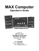
MAX Computer Operator's Guide Copyright 2005 JMI Telescopes Jim's Mobile, Incorporated 8550 West 14th Avenue Lakewood, CO 80215 U.S.A. Phone Fax Order Line Web Site Email (303) 233-5353 (303) 233-5359 (800) 247-0304 jmitelescopes.com sales@jmitelescopes.
Table of Contents INTRODUCTION............................................................................................................. 4 What is Does................................................................................................... 4 What it Doesn't Do .......................................................................................... 4 GETTING STARTED ...................................................................................................... 4 Encoder Test...........
INTRODUCTION accomplish this task. (Some "Go To" telescopes can be software controlled using the SGT-MAX system.) This manual covers the NGC-MAX, NGC-miniMAX and NGC-microMAX computer units. Sections which cover material not common to all of these units are labeled with the models they apply to. GETTING STARTED The MAX family of computers are revolutionary, computerized digital setting circle units with an internal database of hundreds to thousands of astronomical objects.
you will want to be able to reliably return to this same position in a future step. Begin rotating your telescope in its Right Ascension or Azimuth axis (left-to-right) in a clockwise direction as seen from a vantage point directly above the telescope. (Southern Hemisphere users should rotate in the opposite direction.) The first set of displayed digits should increase as the telescope is moved (you will see something similar to 000 ... 001 ... 002 ... 003, etc.).
Alternatively, the encoder can sometimes be re-mounted so that it turns the opposite direction. Bad encoder/cable. While the probability of an encoder or cable being bad is extremely small, it is a possibility. If the problem is isolated to either the cable or encoder, there are a few simple tests which can quickly determine the exact culprit. Follow each point as outlined below, checking the operation of the encoders after each until the problem disappears. 1.
USING YOUR COMPUTER alignment stars (chosen with the UP/DOWN buttons) and then center that star in your telescope's eyepiece. If you wish to start using your MAX computer immediately without reading through the manual, or you just want a quick refresher course, please refer to the Quick-Start Guide found in Appendix E. With the chosen star centered as well as possible in your telescope's eyepiece (not the finder scope), press the ENTER button to align the MAX computer on that star.
the star you are pointing at is indeed the one selected in the MAX computer. For indoor familiarization, the alignment process may be simulated to allow access to additional modes (attempting to select some modes before the alignment process has been completed will result in a STAR SIGHTINGS ARE REQUIRED message). RA DEC This mode displays the Right Ascension and Declination (coordinates) of the direction the telescope is currently pointed.
To add an object to the NEW catalog, enter the CATALOG mode and use the UP/DOWN buttons until NEW01 is displayed. After pressing ENTER, select the object number you wish to modify (01-28). Once you have ENTERed the number, the current coordinates are displayed (if defining for the first time, 2400-000 will appear). Press ENTER once more and the first digit of the Right Ascension will begin flashing.
of eight, then only objects of magnitude 8.0 or brighter will be found. The limiting magnitude range is from one (bright) to 17 (faint). Those objects which do not have a magnitude defined are only found with a limit of 17. When both search parameters have been defined, press ENTER and the computer will display the name of the nearest object meeting your search criteria.
The timer is started by pressing the ENTER button, which will temporarily cause the display to show the following: START The elapsed time from the moment you pressed the ENTER button will then be displayed until you press ENTER to stop the timer or MODE to exit the timer mode. ENCODER This mode is primarily used for verifying proper operation of the encoders. The encoder angles (in whole degrees) relative to their startup positions is shown.
microMAX does not have the EP or GP settings). These represent the following: AV Alt/az Vertical. For use with altitude/azimuth mounts initialized to a vertical* position. AZ Alt/az Zero. For use with altitude/azimuth mounts initialized to a level* (or 0°) position. EQ EQuatorial. For equatorial mounts using a two-star alignment. This must be used if you have a non-polar aligned, non-German, equatorial mount. EP Equatorial Perfect.
Appendix A — Specifications NGC-MAX NGC-miniMAX* NGC-microMAX Size: 14.6cm x 9.1cm x 3.7cm (5.75" x 3.60" x 1.44") 7.0cm x 11.7cm x 3.0cm (2.75" x 4.60" x 1.18") 6.1cm x 9.9cm x 3.0cm (2.40" x 3.88" x 1.18") Weight: 233g (8.2 oz.) 155g (5.4 oz.) 122g (4.3 oz.
Appendix B — NS/DS Catalog Abbreviations AB AN B BA BD BI BK BL BO CE CR Abell Antalova Barnard Basel Baade Biur Berkley Blanco Bochum Cederblad Colinder CZ DD DO FR GU H HA HB HU KI LY MA ME MF MK MR NE PA PI RO RU SH2 Czernik Dolidze-Dzimselejsvili Dolidze Frolov Gum Harvard Haffner Hubble Humason King Lynza Markarian Melotte Maffei Minkowski Merrill New Palomar Pismis Roslund Ruprecht Sharpless SP ST TO TR TZ U VB Stephenson Stock Tombaugh Trumpler Terzian Upsala Van Den Burgh Appendix C — RS-232
Appendix D — Sample BASIC Program Listing The following program listing has been tested on numerous MS-DOS compatible computers using both GW-BASIC and QBASIC. While all efforts have been made to ensure error-free code, the user is solely responsible for the accurate entry and operation of this program.
Appendix E — MAX Quick-Start Guide NOTE: For best results, the following steps should be followed while using the telescope under actual observing conditions. Simulated star alignments may be used for the purpose of familiarizing yourself with the operation of the computer, however, the user should be aware that under these conditions the coordinate display and GUIDE mode will behave unpredictably. 1. Turn unit ON. A message will appear briefly. 2.