StorBlade TM 1U SCSI JBOD 4-bay Rackmount Enclosure Installation Guide October 3, 2002 • Revision A Patent Pending
StorBladeTM Copyright Copyright 1998, 1999, 2001 by JMR Electronics, Inc. All Rights Reserved. No part of this publication may be reproduced, transmitted, transcribed, stored in a retrieval system, or translated into any language, in any form or by any means, electronic, mechanical, photocopying, recording or otherwise, without the express written permission of JMR Electronics, Inc. Sales and Ordering Information JMR Electronics, Inc.
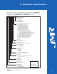
StorBladeTM Table of Conte nts Table of Contents 1. Introduction 2/4/6/8/10/12/15-bay Product Family Features . . . . . . . . . . . . . . . . . . . . . .1-1 4-bay Rackmount Specifications . . . . . . . . . . . . . . . . . . . . . . . . . . . . . . . . .1-2 SCSI Features . . . . . . . . . . . . . . . . . . . . . . . . . . . . . . . . . . . . . . . . . . . . . . . .1-2 Daisy Chaining . . . . . . . . . . . . . . . . . . . . . . . . . . . . . . . . . . . . . . . . . . . .1-2 ID Selection . . . . . . . . . . .
StorBladeTM 6. 1U04 Cabinet Installation Rail Mounting Kit Hardware . . . . . . . . . . . . . . . . . . . . . . . . . . . . . . . . . . . .6-2 Spare Hardware Parts . . . . . . . . . . . . . . . . . . . . . . . . . . . . . . . . . . . . . . . . . .6-2 Rail Installation . . . . . . . . . . . . . . . . . . . . . . . . . . . . . . . . . . . . . . . . . . . . . . .6-2 7. Product Support US Corporate Headquarters . . . . . . . . . . . . . . . . . . . . . . . . . . . . . . . . . . . . .7-1 Manual Changes . . . .
1. Introduction The 4-bay StorBladeTM 1U SCSI JBOD enclosure is designed for use with a host system to provide a high-end storage solution. The following is a summary of the 4-bay 1U enclosure features: • The 4-bay StorBladeTM 1U SCSI JBOD Rackmount enclosure is a four drive enclosure that supports up to four 3.5" LP (Low-Profile) SCA (80pin) drives. It supports single-ended, Ultra2 SCSI, and Ultra 160 SCSI. The SCSI enclosure has two SE/LVD (single-ended/Low Voltage Differential) Channels.
StorBladeTM StorBladeTM products use advanced mid-plane technology developed by JMR, that allows power supplies, drives, and all other enclosure components to interface into a single board. This provides superior performance and easy connectivity. The host interface supports single-ended, Wide Ultra2 SCSI (LVD), and Ultra 160. Connections to a SCSI host can be made using a 68-pin (HD68) SCSI cable. 4-bay Rackmount Specifications Dimensions/Weight Unit Weight 35 lbs. (15.9kg) Height 1-3/4" (1U) (44.
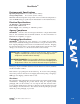
2. Hardware Specification This chapter covers specification information for the 4-bay StorBladeTM enclosures. The following matrix describes the identification codes for the available configurations for all FORTRA and the StorBladeTM enclosures.
StorBladeTM Environmental Specifications Operating Temperature: 5°C to 40°C (41°F to 104°F) Storage Temperature: 0°C to 65°C (32°F to 149°F) Maximum ambient temperature is dependent on the recommended temperature to meet the MTBF rating as specified by the manufacturer of the installed devices.
StorBladeTM Thermal Specifications StorBladeTM enclosures have been designed to meet the air-flow/cooling requirements for popular 7,200, 10,000 and 15,000 RPM disk drives. Using a high performance blower, air is pulled in from all open vents and exhausted out the back of the unit. Rotation Vibration Specifications StorBladeTM enclosures have been designed to meet the rotation vibration/shock requirements for popular 7,200, 10,000 and 15,000 RPM disk drives.
3. Device Installation This chapter covers SCSI device installation for 4-bay 1U rackmount enclosures. SCA Connection and Hot-Swapping The unit uses SCA-2 type connectors which provide a safe means of connection/disconnection when hot-swapping devices. In order to utilize this feature, the host adapter or RAID controller and host operating software must support the feature.
StorBladeTM 2. Place the device in the canister with the four screw holes aligned with the holes in the device. Mount the drive by using the screws included with the unit. (use all 4 screws to mount the drive). 3. Replace the canister into the unit. 4. Repeat steps 1 through 3 until all devices are installed. 5. Configure ID, and other options as required 6.
4. SCSI Setup This chapter covers SCSI device setup and option settings. Please take note of the installation warnings below before beginning setup. WARNING: Take care when connecting the unit to an AC power source to ensure that it is plugged-in to a circuit of the appropriate rating (110v or 220v). For safe operation, the circuit should have over-current protection to prevent damage to the unit in the event of circuit overloading.
StorBladeTM Setting ID The basic personality card has jumpers available on the personality card to set the ID for each slot. To access the jumpers the top cover must be removed. The following picture indicates the location of jumpers W1-W4. W4 W3 W2 W1 NOTE: View is from rear of the unit. There are 4 jumpers on the personality card (W1, W2, W3, and W4) for hard setting the ID of each slot.
StorBladeTM ID Conflict When two devices share the same SCSI ID, a conflict occurs. This conflict must be corrected before the SCSI bus will work properly. If a conflict occurs, check all jumper settings to ensure that no devices on the bus share the same ID. Also check all other devices on the bus outside of the enclosure. Front Status LEDs A status indicator is located on each canister. A 'Blue' light indicates normal drive activity. A 'Red' light indicates a device fault.
StorBladeTM The SCSI In ports are used to connect to a host and require an external cable with a 68-pin High-Density male connector to mate at the enclosure side. Cables are not included. Each SCSI channel must use a separate external cable connection from the rackmount to the host adapter or RAID controller. It is important that the external cable length and impedance is taken into consideration and is adequate for the devices and SCSI speeds being used.
StorBladeTM JMR carries its own line of high-quality external StorBladeTM compatible SCSI cables. The following Table lists JMR part numbers and descriptions. Please contact a JMR representative for current availability and pricing.
5. Power Supply and Blowers This section covers operation of the power supply and blowers. Power Supply Removal/Insertion In the 1U04 SCSI JBOD enclosure, the power supply is not a field replaceable unit (FRU). Therefore, if you have a power supply malfunction, contact Technical Support at JMR Electronics. See Chapter 7 for contact information. Blower Removal/Insertion In the 1U04 SCSI JBOD enclosure, there are two blowers that are not field replaceable units.
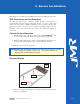
6. 1U04 Cabinet Installation This chapter covers the installation of the Rackmount enclosure into a standard 19" (483mm) wide and 30" (762mm) to 36" (914mm) deep cabinet that meets the EMA/RETMA standards. Before beginning rail installation, please take note of the following precautions: NOTE: When installing the unit into a cabinet or closed environment, the operating ambient temperature of the rack environment may be greater than the maximum recommended ambient temperature.
StorBladeTM Rail Mounting Kit Hardware • • Eight #10-32 Screws Four each #8-32 Screws/Washers/Nuts Spare Hardware Parts Check with a JMR Sales Representative for pricing and availability of spare hardware parts. Description #10-32 Screw #8-32 Screw #8-32 Nut #8-32 Washer JMR Part Number HDS-01580 HDS-00350 HDN-00040 HDW-00080 Rail Installation Expansion Rail Main Rail Rear Front 1. Affix the extension brackets to the main rail using the #8-32 screw/washer/nut assemblies.
StorBladeTM 2. Affix the extension bracket to the rear of the unit using two #10-32 screws. There are 3 holes in the extension bracket for mounting. Depending on the hole pattern that is being used in the cabinet, two holes should always be available for securing the extension bracket. 3. The fronts of the rails have three holes. Two of the holes (top and bottom) are used to secure the rail to the cabinet. The middle hole is used to secure the enclosure to the rail and cabinet.
7. Product Suppor t For current information on this product, including updates to the manual and technical support related issues, please contact the sales support section of our web page at www.jmr.com, or you can contact our Technical Support division directly at the address below. US Corporate Headquarters JMR Electronics, Inc. ATTN: Technical Support Division 20400 Plummer St. Chatsworth, CA 91311 Customer Support: (818) 739-1140 E-mail: techsupport@jmr.com Office Hours: Monday-Friday 8:00 A.M.
Appendix A. Drive and Controller Manufacturers Drive Manufacturers Fujitsu Internet Address: www.fcpa.com Hitachi Internet Address: www.hitachi.com IBM (International Business Machines Corporation) Internet Address: www.ibm.com Maxtor Internet Address: www.maxtor.com Seagate Technology Internet Address: www.seagate.com RAID Controller Manufacturers Adaptec, Inc. Internet Address: www.adaptec.com Chaparral Network Storage Internet Address: www.chaparralnet.com Digi-Data Corporation Internet Address: www.
StorBladeTM Host Bus Adapter Manufacturers Adaptec, Inc. Internet Address: www.adaptec.com Antares Microsystems Internet Address: www.antares.com Emulex Corporation Internet Address: www.emulex.com JNI Corporation Internet Address: www.jni.com QLogic Corp. Internet Address: www.qlogic.