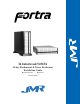
I6 Infortrend 5251F6 15-bay Rackmount & Tower Enclosures Installation Guide October 22, 2003 • Revision A Patent Pending
Copyright Copyright 2003 by JMR Electronics, Inc. All Rights Reserved. No part of this publication may be reproduced, transmitted, transcribed, stored in a retrieval system, or translated into any language, in any form or by any means, electronic, mechanical, photocopying, recording or otherwise, without the express written permission of JMR Electronics, Inc. Sales and Ordering Information JMR Electronics, Inc.
Table of Contents Table of Contents 1. Introduction 2/4/6/8/10/12/15-bay Product Family Features . . . . . . . . . . . . . . . . . . . . .1-1 Rackmount Specifications . . . . . . . . . . . . . . . . . . . . . . . . . . . . . . . . . . . . .1-2 Tower Specifications . . . . . . . . . . . . . . . . . . . . . . . . . . . . . . . . . . . . . . . . .1-2 Fibre Channel Features . . . . . . . . . . . . . . . . . . . . . . . . . . . . . . . . . . . . . . .1-3 Loop Expansion . . . . . . . . . . . . . . . . . . . . . .
Host CH-0 and CH-1 (Top) . . . . . . . . . . . . . . . . . . . . . . . . . . . . . . . . .4-4 CH 2 (Bottom) . . . . . . . . . . . . . . . . . . . . . . . . . . . . . . . . . . . . . . . . . . .4-4 CH 3 (Top) . . . . . . . . . . . . . . . . . . . . . . . . . . . . . . . . . . . . . . . . . . . . . .4-5 CH 4 . . . . . . . . . . . . . . . . . . . . . . . . . . . . . . . . . . . . . . . . . . . . . . . . . . .4-5 CH 5 . . . . . . . . . . . . . . . . . . . . . . . . . . . . . . . . . . . . . . . . . . . . . . .
1. Introduction The 15-bay FORTRA I6 Infortrend 5251F6 enclosures are designed to be used with a host system to provide a high-end RAID subsystem. The following is a summary of the 15-bay Rackmount and Tower enclosure features: • The 15-bay FORTRA I6 Infortrend 5251F6 Tower enclosure supports up to fifteen LP SCA 40-pin SCA drives. This model supports up to six 2Gb/s Fibre Channel loops. The Fibre Channel enclosure has dual or quad fibre channel host ports and dual or quad fibre channel drive ports.
FORTRA products use advanced mid-plane technology developed by JMR, which allows power supplies, drives, and all other enclosure components to interface into a single board. This provides superior performance and easy connectivity. The host interface supports SFP Fibre Channel connections at 2Gb/s. All 15-bay FORTRA 2Gb/s Fibre enclosures have built-in SES on the personality card that allows control and monitoring of some enclosure components.
Blower Quantity: Size: Air Flow: Noise: 4 (2 per cannister) 97mm (3.82") each 25.42CFM (0.72m3/min) each 52dB(A) Fibre Channel Features Loop Expansion FORTRA 15-bay 2Gb/s Fibre Channel JBOD enclosures include a loop expansion I/O connector on each fibre channel drive port. This allows the connection to other Fibre Channel JBOD enclosures. Loop Bypass and Clock Timing Circuit Each port includes a loop bypass circuit that monitors each slot for a loop connection.
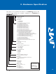
2. Hardware Specification This chapter covers specification information for all FORTRA enclosures. The following matrix describes the available configurations for FORTRA and StorBladeTM enclosures.
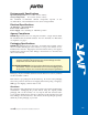
Environmental Specifications Operating Temperature: 5°C to 40°C (41°F to 104°F) Storage Temperature: 0°C to 65°C (32°F to 149°F) The maximum recommended ambient temperature depends on the recommendation of the manufacturer for the devices being installed.
Thermal Specifications FORTRA enclosures have been designed to meet the air-flow/cooling requirements for popular 7,200, 10,000 and 15,000 RPM disk drives. Using high performance blowers, air is pulled in from all open vents and exhausted out the back of the unit. Rotation Vibration Specifications FORTRA enclosures have been designed to meet the rotation vibration/shock requirements for popular 7,200, 10,000, and 15,000 RPM disk drives.
3. Device Installation This chapter covers Fibre Channel device installation for 15-bay rackmount and15-bay tower enclosures. SCA Connection and Hot-Swapping The unit uses SCA-2, 40-pin connectors which provide a safe means of connection/disconnection when hot-swapping devices. In order to hot-swap devices, the host adapter or RAID controller and host operating software must support the feature.
Drive Installation Device Mounting Holes (4) Status Indicators Handle Device mounting screws are included with the unit for device mounting. The JMR part number for the #6-32" mounting screws is HDS-01906. WARNING: Before device installation, alleviate any electro-static discharge by touching a grounded metal assembly. Static can be potentially damaging to enclosure components. WARNUNG: Berühren Sie vor der Festplatteninstallation geerdete Metallgegenstände, um elektro statische Aufladung abzuleiten.
4. Repeat steps 1 through 3 until all devices are installed, then move onto step 5 to complete unit setup and installation. 5. Configure ID and other options as required. See Chapter 4 for device setup. 6. For 15-bay rackmount units, refer to Chapter 7 to install the enclosure into a cabinet. 7. Establish host connection. See Chapter 4 for host connection.
4. Fibre Channel Setup This chapter covers Fibre Channel device configuration and option settings. All Fibre Channel 15-bay units have built-in SES on the personality card. Refer to Chapter 8 for SES operation. Please take note of the installation warnings below before beginning setup. WARNING: Take care when connecting the unit to an AC power source to ensure that it is plugged-in to a circuit of the appropriate rating (110v or 220v).
Setting ID Rotary switch settings only affect Slot 0 and all other slots are sequentially increased by a value of one after that slot. The ID is set sequentially starting from a base address. The base address, or starting address, is set via a 0-7 position rotary switch located on the personality module. There is a second 0-15 position rotary switch which can be changed to modify the base address setting. The default value for both switches is 0.
ID Conflict When two devices share the same ID, a conflict occurs. This should not happen unless two or more enclosures are daisy chained together. If devices in one enclosure conflict with devices in another enclosure, the devices will re-arbitrate ID and resolve the conflict. Option Settings Three option settings are located on the personality card. To access the jumpers, the cover must be removed. The figure below shows the location of the option settings on the personality card.
External I/O Connection The external I/O connections are located on both the personality card and the contoller card. There are five SFP I/O connectors accessible from the rear of the unit as shown in the figure below.
CH 3 (Top) This is a standard (2Gb/s) SFP transceiver connector used to connect to a drive expansion enclosure for Loop B side of drives. The 15 internal drives loop side B are connected to this loop as well. CH 4 This is a standard (2Gb/s) SFP transceiver connector used to connect to a host system or drive expansion bay. Host or disk connection is firmware selectable. CH 5 This is a standard (2Gb/s) SFP transceiver connector used to connect to a host system or drive expansion bay.
5. Blower Operation This chapter covers all operations of the blowers for 15-bay units. Refer to Chapter 1 for blower specifications. The blower is hot swappable and can be removed or installed while the enclosure continues to function, however, failure to replace a non-working blower within a reasonable period of time may expose drives to extreme heat, which could cause loss of data. WARNING: Blowers are a system critical component.
WARNING: Avoid direct contact with the blower intake access hole while the blower is running. The blower operates at high speeds and can cause injury. User’s removing or installing a blower must be awarre of the blower access hole. Contact with the access hole must be avoided while the blower is running to prevent injury. Blower Replacement If the blower has stopped running or the fault LED indicator is lit, the blower may need to be replaced.
6. Power Supply Operation This chapter covers all operations of the power supplies. For operation, the AC cord (included) must be connected to the AC Inlet on each supply, and the power supply must be switched ON. The 'OK LED' will light to indicate the power supply is functioning properly. If the power supply experiences a problem and cannot operate within its normal specifications, the Fault LED will light and the power supply will shut itself off.
Low Power Mode (Standby Power) When both power supplies are turned off, the unit will switch to low power or standby mode and the power supply fans will continue to run. The unit blowers will remain operational if a single power supply is turned off, not installed, or fails, in order to maintain the proper low temperature within the unit. To stop the power supply fans and turn the unit off completely, it must be disconnected from the AC power source.
7. FR15 Cabinet Installation This chapter covers the installation of the Rackmount enclosure into a standard 19" (483mm) wide and 30" (762mm) to 36" (914mm) deep cabinet that meets the EMA/RETMA standards. Before beginning rail installation, please take note of the following precautions: NOTE: When installing the unit into a cabinet or closed environment, the operating ambient temperature of the rack environment may be greater than the maximum recommended ambient temperature.
Rail Mounting Kit Hardware • • Ten #10-32 Screws Four each #8-32 Screws/Washers/Nuts Spare Hardware Parts Check with a JMR Sales Representative for pricing and availability of spare hardware parts. Description #10-32 Screw #8-32 Screw #8-32 Nut #8-32 Washer JMR Part Number HDS-01580 HDS-00350 HDN-00040 HDW-00080 Rail Installation A completed rail assembly without the unit uinstalled would look like this: Two #8-32 screw assemblies Two #10-32 screws Two #1032 screws Cabinet/Unit Front 1.
Extension Bracket 2. Affix the extension bracket to the rear of the unit using two #10-32 screws. There are 3 holes in the extension bracket for mounting. Depending on the hole pattern that is being used in the cabinet, two holes should always be available for securing the extension bracket. 3. The fronts of the rails have three holes. Two of the holes (top and bottom) are used to secure the rail to the cabinet. The middle hole is used to secure the enclosure to the rail and cabinet.
4. Slide the unit into the cabinet and secure it to the cabinet with a single #10-32 screw on each side. 5. Snap the end cap over the screw on each side of the unit to finish the installation.
8. SES Operation For bus management, the FORTRA Fibre channel enclosures have a built-in SES processor designed to meet the SFF-8067 specification. By using the SES (SLink) connector on the back of the unit the SES bus management can be expanded to other FORTRA Fibre enclosures that don't have a SES processor of their own (2/4-bay units). In order to communicate with the SES processor, at least one device must be present in the enclosure.
9. Infor trend 5251F6 Installation This model is designed to be used with up to two 5251F6 RAID bridge controllers from Infortrend. A total of six loops are provided. The table below indicates the possible host and disk combinations. RCC is used for inter controller communication when two controllers are installed. RCC occurs on either a dedicated loop or shared with a disk loop and is firmware selectable.
10. Product Suppor t For current information on this product, including updates to the manual and technical support related issues, please contact the sales support section of our web page at www.jmr.com, or you can contact our Technical Support division directly at the address below. US Corporate Headquarters JMR Electronics, Inc. ATTN: Technical Support Division 20400 Plummer St. Chatsworth, CA 91311 Customer Support: (818) 739-1140 E-mail: techsupport@jmr.com Office Hours: Monday-Friday 8:00 A.M.
Appendix A. Drive and Controller Manufacturers Drive Manufacturers Fujitsu Internet Address: www.fcpa.com Hitachi Global Storage Technologies Internet Address: www.hgst.com Maxtor Internet Address: www.maxtor.com Seagate Technology Internet Address: www.seagate.com RAID Controller Manufacturers Adaptec, Inc. Internet Address: www.adaptec.com Chaparral Network Storage Internet Address: www.chaparralnet.com Infortrend Corporation Internet Address: www.infortrend.