
- Frontier Equipment Compact Loader User Manual


30-200-4
60, 90, and 125 Skid-Steer Loaders
D
Hydrostatic Drive Operation-
60 and 90 Loaders-Continued
0
0
PUMP
~
FILTER
CSM949
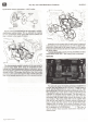
Each pump is connected by hose routing to a hydrostatic
gear motor. Hydraulic fluid is drawn by the pumps from the
reservoirthrough a filter. The pumps then deliver the pres-
surized fluid to the motors.
REAR PRIVE SPROCKET
\
"'"
FRONTDRIVE SPROCKET
(90 Skid-Steer Loader shown)
Sprockets on the output shaft of each motor are connect-
ed to each axledrive sprocket by a one-step drive chain, in
order-to obtain four-wheel drive.
CSM950
Aug. 84 Utho in U.S.A.
(60 Skid-Steer Loader shown)
The motors and chains of the 60 Skid-Steer Loader are
located under the floor panel, in the 18-U.s.-gallon reservoir,
for cooling and lubrication.
(90 Skid-Steer Loader shown)
On the 90 Skid-Steer Loader, the ratio between engine
horsepower,hydrostatic motor sizeand reservoir sizeis such
that the motors have sufficient coolingwithout being placed
in the hydraulic reservoir.The chains are located in 1.5-U.S.-
gallon chain cases for lubrication ("A" above).
The 90 Loader features a T-bar, and the 60 Loader uses
two levers to control the direction and ground speed of the
loader. Two-lever control is necessary on the 60, in order to
allow easy entry and exit of its narrow operator station.
Aneutral start safety switch is provided at the base of the
drive clutch lever. This means that the pumps must be dis-
engaged before the engine will crank.