FWU JOHN DEERE WORLDWIDE COMMERCIAL & CONSUMER EQUIPMENT DIVISION Lawn Care Tools Tow-Behind OMM138188 G0 North American Version Litho in U.S.A.
INTRODUCTION Introduction Thank You for Purchasing a John Deere Product IMPORTANT: Avoid damage! This text is used to tell the operator of actions or conditions that might result in damage to the machine. We appreciate having you as a customer and wish you many years of safe and satisfied use of your machine. NOTE: General information is given throughout the manual that may help the operator in the operation or service of the machine.
PRODUCT INFORMATION Product Information Record Product Information Tow-Behind Lawn Care Tools Thatcherator, Plug Aerator, Spiker Aerator, Aerator/ Spreader, and Lawn Roller In the event you need to contact an Authorized Service Center for information on servicing your product, record the following information in the spaces provided below.
TABLE OF CONTENTS Table of Contents Safety .....................................................................................................................................................................................1 Installing .................................................................................................................................................................................4 Removing ......................................................................................
SAFETY Understanding The Machine Safety Labels Operate Safely The machine safety labels shown in this section are placed in important areas on your machine to draw attention to potential safety hazards. • Know your controls and how to stop quickly. Read your machine Operator’s Manual. On your machine safety labels, the words DANGER, WARNING, and CAUTION are used with this safety-alert symbol, (c). DANGER identifies the most serious hazards.
SAFETY • DO NOT let children or an untrained person operate machine. • Do not wear radio or music headphones while operating the machine. Safe operation requires your full attention. details on chemical products: physical and health hazards, safety procedures, and emergency response techniques. The seller of the chemical products used with your machine is responsible for providing the MSDS for that product.
SAFETY 5. Stop the engine. 6. Remove the key. 7. Wait for engine and all moving parts to stop before you leave the operator’s seat. 8. Close fuel shut-off valve, if your machine is equipped. Tire Safety Explosive separation of a tire and rim parts can cause serious injury or death: • Do not attempt to mount a tire without the proper equipment and experience to perform the job. • Always maintain the correct tire pressure. Do not inflate the tires above the recommended pressure.
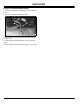
INSTALLING Installing Installing Tow-Behind Attachment 1. Park tractor safely. (See Parking Safely in the SAFETY section.) 2. Place the attachment behind the tractor. C B A D M56880 3. Place clevis (A) onto tractor hitch plate (B). Align the hitch pin holes. 4. Install hitch pin (C) through holes in clevis and hitch plate. 5. Secure spring locking pin (D) through hole in hitch pin.
REMOVING Removing Removing Tow-Behind Attachment 1. Park tractor safely. (See Parking Safely in the SAFETY section.) c CAUTION: Avoid injury! Do not attempt to disconnect attachment from tractor with weight or spreading material remaining in the unit. Attachment could become unstable causing injury. 2. Remove all weight and/or material from attachment. B C A M56880 3. Remove spring locking pin (A). 4. Remove hitch pin (B). 5. Move attachment off tractor hitch plate. 6.
OPERATING - THATCHERATOR can be towed without tines contacting the ground. Operating - Thatcherator When to Use the Thatcherator The best times to dethatch are spring and fall. Grass should be less than 76 mm (3 in.) high for proper tine action. Spring dethatching gives the grass a chance to grow strong before summer takes its toll, while a fall treatment will prevent pests from finding a fertile breeding ground in your lawn. Use John Deere’s tow-behind thatcherator to pull up excess thatch.
OPERATING - THATCHERATOR 3. Tow thatcherator to a level concrete or asphalt surface. 4. Park tractor safely. (See Parking Safely in the SAFETY section.) A 5. Place lift handle in center hole for detaching position. 6. Loosen bolts (A) on each side of weight tray mounting brackets. TY9167 • In free position (A), tines are relaxed and not working. 7. Raise or lower weight tray to place tine tips about 13 mm (1/2 in.) above ground surface. 8. Tighten the weight tray bolts completely. 9.
OPERATING - THATCHERATOR 2. Install thatcherator to tractor. 3. Place unit in transport position. 4. Add recommended weight to weight tray. 5. Place unit in desired operating position. 6. Adjust unit to proper depth. 7. Place unit in transport position. 8. Drive to work area. 9. Park tractor safely. (See Parking Safely in the SAFETY section.) 10.Place thatcherator in desired operating position. 11.Start machine. 12.Tow thatcherator at 5 to 8 km/hr (3 to 5 mph) for safe and effective operation. 13.
OPERATING - PLUG AERATOR desired position: Operating - Plug Aerator When to Use the Plug Aerator The plug aerator will remove plugs of soil up to 76 mm (3 in.) deep, allowing penetration of water and nutrients for a healthier lawn. It also helps reduce compaction of soil. Use the plug aerator only on an established lawn, never on newly laid sod. The plug aerator should not be used when lawn conditions are too wet or too dry. To determine condition, dig a small amount of your soil, about 76 mm (3 in.
OPERATING - PLUG AERATOR hole should appear every 25 to 30 cm (10 to 12 in.) and not more than 76 mm (3 in.) deep. 9. Tow plug aerator at 5 to 8 km/hr (3 to 5 mph) for safe and effective operation. Add or remove weight to obtain this condition. 10.Check for proper hole pattern and depth. Park tractor safely before making any adjustments. Checking Tractor Ground Speed • Check ground speed in an open area. • Measure a test area that is 30.5 m (100 ft) in length.
OPERATING - SPIKER AERATOR Operating - Spiker Aerator When to Use the Spiker Aerator A The spiker aerator will actively penetrate soil, allowing much needed air, water, and nutrients to enter the lawn. It will also relieve soil compaction. A moderate soil moisture content is important to proper operation of the spiker aerator. Penetration will not occur in extremely dry soil, and very wet conditions will cause the unit to “bog down,” possibly causing lawn damage.
OPERATING - SPIKER AERATOR Checking the Tine Operation section.) Operation of the tines will vary with soil type, condition, and amount of weight in weight tray. Make sure soil conditions are appropriate for operation. Do not exceed the weight tray capacity to try and improve penetration in overly dry conditions. 2. Install spiker aerator to tractor. Test operation of the tines by driving the tractor forward about 3 m (10 ft). Observe the operation. Check for uniform hole pattern and depth. 6.
OPERATING - AERATOR-SPREADER Operating - Aerator-Spreader When to Use the Aerator-Spreader D The aerator-spreader will actively penetrate soil, allowing much needed air, water, and nutrients to enter the lawn. It will also relieve soil compaction and can be used to spread seed or fertilizer while aerating. A B E A moderate soil moisture content is important to proper operation of the aerator-spreader.
OPERATING - AERATOR-SPREADER 5. Unlock the flow control lever. It will open the hopper to the pre-set flow rate setting. tractor forward about 3 m (10 ft). Observe the operation. Check for uniform hole pattern, depth, and spread. Using the Weight Tray and Hopper Add or remove weight if needed to obtain proper aeration results. Adjust ground speed and/or flow control setting to achieve proper spreading results.
OPERATING - AERATOR-SPREADER Metric Applications 1. Determine from material bag, the amount of material to be spread over a designated area. Example: The contents of this bag, 11 kg, will cover 465 m2. 2. Determine the amount of material required to cover 10 m2 as follows: • Add one zero to the bag weight. Example: 110 kg. • Divide this number by the number of square meters on the bag. Example: 110 divided by 465 = 0.24 kg of material for 10 m2.
OPERATING - AERATOR-SPREADER ALTERNATIVE FLOW CONTROL SETTING CHART Very Coarse Fertilizers (Large, heavy pellets and granules) Medium Coarse Fertilizers (Pellets and granules) Light Fertilizers (Nitrogen, etc.) Operating Aerator-Spreader c CAUTION: Avoid injury! Keep hands and feet .24 kg/10 m2 (.5 lb/100 sq ft) 9 .49 kg/10 m2 (1.0 lb/100 sq ft) 12 .73 kg/10 m2 (1.5 lb/100 sq ft) 15 .24 kg/10 m2 (.5 lb/100 sq ft) 7 Always back carefully in a straight line to avoid jackknifing the attachment.
OPERATING - LAWN ROLLER was designed – lawn tractors and lawn and garden tractors. Operating - Lawn Roller When to Use the Lawn Roller Use the lawn roller at any time to pack down new sod, seed, and unlevel ground. Adding Weight to the Lawn Roller c CAUTION: Avoid injury! Never add weight to lawn roller unless unit is installed to tractor. Do not overload your tractor. Fully loaded roller can weigh 177 kg (390 lb). 1. Install lawn roller to tractor.
SERVICE Service Servicing the Attachment D c CAUTION: Avoid injury! Plugging spoons and B tines are sharp. Wear gloves and handle with care. Shield sharp parts during service work. To prevent or eliminate rust on tines or plugging spoons, apply a light oil on them after each use. C For rust appearing on any part of your attachment, sand lightly and coat with enamel.
STORAGE Storage Storing the Attachment c CAUTION: Avoid injury! Plugging spoons and tines are sharp. Wear gloves and handle with care. Store attachments so sharp parts are shielded from contact. 1. Park tractor safely. (See Parking Safely in the SAFETY section.) 2. Remove all weight and material from attachment. 3. Remove attachment from tractor. 4. Wash attachment thoroughly. Allow to dry completely. 5. Replace all worn, damaged, or missing parts. 6. Sand any rusted areas lightly and paint with enamel.
ASSEMBLY - THATCHERATOR Assembly - Thatcherator Identify Parts A I B C H G F Qty. Part Description 1 Carriage Bolt, 5/16 x 2 in. 2 Carriage Bolt, 5/16 x 2-1/4 in. 1 Hex Bolt, 3/8 x 1-1/4 in. 1 Hex Bolt, 3/8 x 1-1/2 in. 2 Hex Bolt, 5/8 x 3-1/4 in. 4 Hex Nut, 5/8 in. 2 Lockwasher, 5/8 in. 2 Flat Washer, 5/16 in. 2 Flat Washer, 3/8 in. 4 Flat Washer, 5/8 in. 2 Hex Locknut, 3/8 in. 1 Hex Nut, 5/16 in. 1 Lockwasher, 5/16 in. 1 Lift Lock Pin 7 Carriage Bolt, 5/16 x 1 in.
ASSEMBLY - THATCHERATOR Install Tow Bars to Tray Assembly C E A B A D B F M56882 2. Assemble two clevis straps (B) to front of tow bars using two 5/16 x 2-1/4 in. carriage bolts (C) and two locknuts (D). Hand tighten only. 3. Slide clevis assembly forward until front carriage bolt is within 6 mm (1/4 in.) from the end of tow bars. 4. Install hitch pin (E) in clevis and fasten with spring locking pin (F) through chain loop. M56881 1.
ASSEMBLY - THATCHERATOR Install Carriage Frame Assembly and Lift Handle F B C J A D I B K A M56883 1. Attach carriage frame assembly (A) (side with two holes should be next to lift lock plate) to rear holes (B) in tow bars and lift lock plate at right side (C). Secure with 3/8 x 1-1/4 in. hex bolt (left side) and 3/8 x 1-1/2 in. (right side lift lock plate), 3/8 in. bushings, 3/8 in. flat washers, and fasten with 3/8 in. locknuts (D). Tighten so bar is secure but free to pivot. M56885 4.
ASSEMBLY - THATCHERATOR NOTE: If length (A) is 22.9 cm (9 in.) or more, wheel is attached at top hole shown in wheel strap (B). Use lower hole if length is less. E F B C G H D M92917A 2. Install one 5/8 in. flat washer (C) onto 5/8 x 3 in. hex bolt (D). 3. Slide wheel onto bolt so side with flat hub surface (not rounded) is seated against washer and bolt head. 4. Install 5/8 in. flat washer (E) and 5/8 in. hex nut (F) onto threaded end of bolt. Tighten nut enough so the wheel can still spin freely.
ASSEMBLY - PLUG AERATOR Assembly - Plug Aerator Identify Parts A Qty. Part Description 7 Nylock Nut, 5/16 in. 3 Medium Lockwasher, 5/16 in. 2 Medium Lockwasher, 1/2 in. 5 Flat Washer, 11/32 x 11/16 x 1/16 in. 1 Flat Washer, 13/32 x 13/16 x 1/16 in. 4 Flat Washer, 17/32 x 1/16 x 3/32 in. 1 Vinyl Handle Grip 2 Clevis 1 Spring B F C E D M78705 Picture Note: 40-Inch model shown. NOTE: The following assembly instructions apply to both the 40-Inch and 48-Inch models.
ASSEMBLY - PLUG AERATOR Install Lift Lever c CAUTION: Avoid injury! Plug Spoons have G I H sharp points. Wear gloves and handle with care. A D B C M56882 5. Install 5/16 x 1-1/2 in. cross hex bolt (I). Place chain hook (H) around bolt and secure with 5/16 in. flat washer and locknut (I). D F E 6. Align tow bars and clevis. Tighten nuts (D) completely. 7. Tighten nylock nut (G) while holding chain hook forward and centered between clevis halves. M78710 1.
ASSEMBLY - PLUG AERATOR H D E G F M78700 M78715 5. Install wheel assembly on lift arm (E). Then install 1/2 in. lockwasher (F) and 1/2 in. hex nut (G). Hold wrench on nut (D) and tighten nut (G) completely. This will ensure the wheel hub remains properly adjusted. 5. Install vinyl handle grip (H) on lift handle. Assemble Transport Wheels 6. Repeat for other wheel assembly. A B M78713 1. Install 1/2 x 3 3/4 in. hex bolt (A) and 17/32 x 1/16 x 3/32 in.
ASSEMBLY - SPIKER AERATOR Assembly - Spiker Aerator Identify Parts A F B C E D Qty. Part Description 4 Flat Washer, 1/2 in. 1 Hex Bolt, 5/16 x 1-1/2 in. 7 Nylock Nut, 5/16 in. 5 Flat Washer, 5/16 in. 1 Special Plow Bolt, 3/8 x 2 in. 1 Flat Washer, 3/8 in. 1 Oblong Locknut, 3/8 in. Assemble Tow Bars M79125 Box of Parts Qty.
ASSEMBLY - SPIKER AERATOR NOTE: You may want to have a helper or use a hoist to steady tow bars during alignment. G C I H F D E D M56882 5. Install 5/16 x 1-1/2 in. cross hex bolt (I). Place chain hook (H) around bolt and secure with 5/16 in. flat washer and locknut (I). 6. Align tow bars and clevis. Tighten nuts (D) completely. 7. Tighten nylock nut (G) while holding chain hook forward and centered between clevis halves. M79127 2.
ASSEMBLY - SPIKER AERATOR and 1/2 in. hex nut (D). 3. Tighten nut (D) until washers (B) and (C) keep bearing from turning on bolt without forcing bearings to be pressed inward. This causes wheel hub to rotate on bearings. H G E D E F M79130 G F M79128 M79130 4. Turn tray upright and install two 5/16 in. transport lock pins (G), extending pin to the outside, and fasten with 5/16 in. lockwashers, and 5/16 in. hex nuts (H) to the inside. Tighten nuts. 4.
ASSEMBLY - AERATOR-SPREADER Assembly - Aerator-Spreader Identify Parts A Qty. Part Description 2 Carriage Bolt, 5/16 x 2-1/4 in. 1 Special Plow Bolt, 3/8 x 2 in. 3 Hex Head Bolt, 5/16 x 3/4 in. 1 Hex Bolt, 5/16 x 1-1/4 in. 2 Hex Bolt, 1/2 x 3-3/4 in. 4 Hex Nut, 5/16 in. 4 Hex Nut, 1/2 in. 4 Lockwasher, 5/16 in. 2 Lockwasher, 1/2 in. 1 Flat Washer, 5/16 in. 1 Flat Washer, 3/8 in. 4 Flat Washer, 1/2 in. 1 Locknut, 3/8 in. 10 Nylock Nut, 5/16 in.
ASSEMBLY - AERATOR-SPREADER Assemble Tow Bars A D A C B C M78714 2. Turn wheel over to install second 1/2 in. flat washer (C) and 1/2 in. hex nut (D). 3. Tighten nut (D) until washers (B) and (C) keep bearing from turning on bolt without forcing bearings to be pressed inward. This causes wheel hub to rotate on bearings. M93661 1. Align tow bars (A) as shown. 2. Align support strap (B) between tow bars and fasten with two 5/16 x 1-1/2 in. hex bolts and nylock nuts (C). Hand tighten only.
ASSEMBLY - AERATOR-SPREADER and locknut (K). 7. Align tow bars and clevis. Tighten nuts (F) completely. C 8. Tighten nylock nut (K) while holding chain hook forward and centered between clevis halves. B D M79139 C 3. Install three transport lock pins (B) into lift plate (C) as shown and fasten with three 5/16 in. lockwashers and hex nuts (D). M93662 E 9. Tighten tow bar nylock nuts (C). Install Tow Bars, Wheel Assembly, and Lift Lever to Hopper F M93641 4.
ASSEMBLY - AERATOR-SPREADER Install Hopper Flow Control Lever I c CAUTION: Avoid injury! Aerator Tines are J extremely sharp. Wear gloves and handle with care. H A M93643 10.Install 3/8 x 2 in. special bolt (H), head of bolt to the inside, into right wheel assembly bracket (I). M93646 K 1. Stand hopper assembly on its back. 2. Remove 5/16 x 1-1/2 in. hex bolt, two large flat washers, and locknut (A) from hopper. L M N M93644 B 11.
ASSEMBLY - AERATOR-SPREADER Install Weight Tray D E A B C M93649 5. Slide lever down between hopper and spike assembly and install other end of shutter link (D) into shutter arm (E). M93645 1. Install last transport lock pin (A) into center hole of rear hopper lip and fasten with 5/16 in. lockwasher (B) and hex nut (C). A A D M93651 6. Slide lever up to align pivot hole with hopper hole and fasten with 5/16 x 1-1/2 in.
ASSEMBLY - LAWN ROLLER Install Scraper Frame Bar Assembly - Lawn Roller Identify Box of Parts A B C A B D E D E C M56870 M92910 Box of Parts A Qty. Part Description 1 Roller Drum (A) 1 Scraper Bar Frame (B) 2 Bar Frame (C) 1 Tethered Pin Assembly (D) 1 Bag of Parts (E) B M56872 1. Insert a 5/8 in. nylon bearing (A), from inside out, into round hole at each end of scraper frame bar (B). Bag of Parts Qty.
ASSEMBLY - LAWN ROLLER using rear set of holes, and secure with a 5/16 x 1-1/2 in. hex bolt (F) and 5/16 in. nylock nut (G). Hand tighten only. E D I K J M56874 3. Slide one end of the scraper frame bar on one end of roller assembly and then spring the other end of scraper frame bar open and slide it over the opposite end of roller axle as shown. 4. Install another 5/8 in. flat washer (D) over each end of axle and secure with a 5/8 in. snap ring (E). H L M56882 3.
SPECIFICATIONS Specifications Thatcherator Width . . . . . . . . . . . . . . . . . . . . . . . . . . . . . . . . . . . . . . . . . . . . . . . . . . . . . . . . . . . . . . . . . . . . . . . . . . . . . 101.6 cm (40 in.) Number of Tines . . . . . . . . . . . . . . . . . . . . . . . . . . . . . . . . . . . . . . . . . . . . . . . . . . . . . . . . . . . . . . . . . . . .20, spring-loaded Weight Tray Capacity . . . . . . . . . . . . . . . . . . . . . . . . . . . . . . . . . . . . . . . . . . . . . . . . . .
SPECIFICATIONS Tine Penetration . . . . . . . . . . . . . . . . . . . . . . . . . . . . . . . . . . . . . . . . . . . . . . . . . . . . . . . . . . . . . . . . . Up to 51 mm (2 in.) Number of Tines . . . . . . . . . . . . . . . . . . . . . . . . . . . . . . . . . . . . . . . . . . . . . . . . . . . . . . . . . . . . . . . . . . . . . . . . . . . . . . . 132 Tine Spacing . . . . . . . . . . . . . . . . . . . . . . . . . . . . . . . . . . . . . . . . . . . . . . . . . . . . . . . . . . . . . . . . . . . . . .
INDEX S Index A Aerator-Spreader Flow Control, Using ........................... 13 Aerator-Spreader Operating Positions, Selecting .......... 13 Aerator-Spreader, Operating .......................................... 16 Aerator-Spreader, When to Use the ............................... 13 F Flow Control Setting (Alternative Method), Determining 14 Flow Control Setting, Determining .................................. 14 Flow Control, Using the Aerator-Spreader .....................
JOHN DEERE QUALITY STATEMENT John Deere Quality Statement John Deere Quality John Deere equipment is more than just a purchase, it’s an investment in quality. That quality goes beyond our equipment to your John Deere dealer’s parts and service support. This support is needed to keep you a satisfied customer. That’s why John Deere has initiated a process to handle your questions or problems, should they arise. The following three steps will help guide you through the process.