POWER Units for Gensets (Saran) 2.9L/4039/4.5/6.
Introduction THIS MANUAL COVERS the following engines for generator sets: ENGINE FAMILY 300-SERIES POWERTECH ENGINE MODEL CD3029DF128 CD4039DF008 CD4039TF008 CD4045DF158 CD4045HF158 CD4045TF158 CD4045TF258 CD6068HF158 CD6068TF158 CD6068TF258 READ THIS MANUAL carefully to learn how to operate and service your engine correctly. Failure to do so could result in personal injury or equipment damage.
Contents Page Page Identification Views Identification views . . . . . . . . . . . . . . . . . . . . . . . 01-1 Diesel Engine Coolant . . . . . . . . . . . . . . . . . . . . 10-4 Operating in Warm Temperature Climates . . . . . 10-5 Maintenance Records Using maintenance records 100 Hours of operation. . . . 500 Hours of operation. . . . 1000 Hours of operation . . . 1500 Hours of operation . . . 2000 Hours of operation . . . 2500 Hours of operation . . . 3000 Hours of operation . . .
Contents Page Checking crankshaft vibration damper (6-CYLINDER ENGINE ONLY) . . . . . . . . . . . 40-4 Maintenance/2500 hours/3 years Drain and flush cooling system . . . . . . . . . . . . . 45-1 Maintenance/As required Additional service information . . . . . . . . . . . . . Do not modify fuel system . . . . . . . . . . . . . . . Clean or replace air filter (one-piece) . . . . . . Clean or replace air filter element . . . . . . . . . Replacing fan and alternator belt (POWERTech ENGINES) . . . . . . . . .
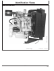
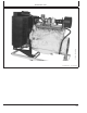
Identification Views CD30744 –UN–23AUG99 IDENTIFICATION VIEWS 4045HF158 Continued on next page 01-1 DPSG,CD03523,3 –19–05JUL99–1/2 112699 PN=5
CD30745 –UN–23AUG99 Identification Views 6068HF158 DPSG,CD03523,3 –19–05JUL99–2/2 01-2 112699 PN=6
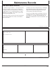
Maintenance Records USING MAINTENANCE RECORDS To obtain the best performance, economy and service life from your engine, ensure service is carried out according to this present manual and recorded in the following pages. It is recommended that your engine Distributor or your Dealer carry out this service work and stamp the appropriate case. Keeping an accurate account of all service performed on your engine will give more value to the machine when you resell it.
Maintenance Records 500 HOURS OF OPERATION ❒ Engine oil, replace ❒ Engine oil filter, replace ❒ Fuel filter, replace ❒ Belt, check tension and wear (300-Series and POWERTech with manual tensioner) ❒ Valve clearance, adjust (300-Series) Number of hours: Comments: Dealer or distributor stamp Date: Job done by: DPSG,CD03523,8 –19–05JUL99–1/1 1000 HOURS OF OPERATION ❒ Engine oil, replace ❒ Air intake system, check ❒ Engine oil filter, replace ❒ Fuel filter, replace ❒ Check belt and tensioning system ❒
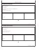
Maintenance Records 1500 HOURS OF OPERATION ❒ Engine oil, replace ❒ Engine oil filter, replace ❒ Fuel filter, replace ❒ Belt, check tension and wear (300-Series and POWERTech with manual tensioner) ❒ Valve clearance, adjust (300-Series) Number of hours: Comments: Dealer or distributor stamp Date: Job done by: DPSG,CD03523,10 –19–05JUL99–1/1 2000 HOURS OF OPERATION ❒ Engine oil, replace ❒ Cooling system, drain and flush (if COOL-GARD is not used) ❒ Engine oil filter, replace ❒ Valve clearance, adj
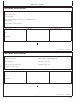
Maintenance Records 2500 HOURS OF OPERATION ❒ Engine oil, replace ❒ Cooling system, drain and flush (if COOL-GARD is used) ❒ Engine oil filter, replace ❒ Fuel filter, replace ❒ Belt, check tension and wear (300-Series and POWERTech with manual tensioner) ❒ Valve clearance, adjust (300-Series) Number of hours: Comments: Dealer or distributor stamp Date: Job done by: DPSG,CD03523,60 –19–16AUG99–1/1 3000 HOURS OF OPERATION ❒ Engine oil, replace ❒ Air intake system, check ❒ Engine oil filter, repla
Maintenance Records 3500 HOURS OF OPERATION ❒ Engine oil, replace ❒ Engine oil filter, replace ❒ Fuel filter, replace ❒ Belt, check tension and wear (300-Series and POWERTech with manual tensioner) ❒ Valve clearance, adjust (300-Series) Number of hours: Comments: Dealer or distributor stamp Date: Job done by: DPSG,CD03523,62 –19–16AUG99–1/1 4000 HOURS OF OPERATION ❒ Engine oil, replace ❒ Cooling system, drain and flush (if COOL-GARD is not used) ❒ Engine oil filter, replace ❒ Valve clearance, ad
Maintenance Records 4500 HOURS OF OPERATION ❒ Engine oil, replace ❒ Vibration damper, replace (6 cyl.
Maintenance Records 5500 HOURS OF OPERATION ❒ Engine oil, replace ❒ Engine oil filter, replace ❒ Fuel filter, replace ❒ Belt, check tension and wear (300-Series and POWERTech with manual tensioner) ❒ Valve clearance, adjust (300-Series) Number of hours: Comments: Dealer or distributor stamp Date: Job done by: DPSG,CD03523,66 –19–16AUG99–1/1 6000 HOURS OF OPERATION ❒ Engine oil, replace ❒ Cooling system, drain and flush (if COOL-GARD is not used) ❒ Engine oil filter, replace ❒ Valve clearance, ad
Maintenance Records 6500 HOURS OF OPERATION ❒ Engine oil, replace ❒ Engine oil filter, replace ❒ Fuel filter, replace ❒ Belt, check tension and wear (300-Series and POWERTech with manual tensioner) ❒ Valve clearance, adjust (300-Series) Number of hours: Comments: Dealer or distributor stamp Date: Job done by: DPSG,CD03523,68 –19–16AUG99–1/1 7000 HOURS OF OPERATION ❒ Engine oil, replace ❒ Air intake system, check ❒ Engine oil filter, replace ❒ Fuel filter, replace ❒ Check belt and tensioning syste
Maintenance Records 7500 HOURS OF OPERATION ❒ Engine oil, replace ❒ Cooling system, drain and flush (if COOL-GARD is used) ❒ Engine oil filter, replace ❒ Fuel filter, replace ❒ Belt, check tension and wear (300-Series and POWERTech with manual tensioner) ❒ Valve clearance, adjust (300-Series) Number of hours: Comments: Dealer or distributor stamp Date: Job done by: DPSG,CD03523,70 –19–16AUG99–1/1 8000 HOURS OF OPERATION ❒ Engine oil, replace ❒ Cooling system, drain and flush (if COOL-GARD is not
Maintenance Records 8500 HOURS OF OPERATION ❒ Engine oil, replace ❒ Engine oil filter, replace ❒ Fuel filter, replace ❒ Belt, check tension and wear (300-Series and POWERTech with manual tensioner) ❒ Valve clearance, adjust (300-Series) Number of hours: Comments: Dealer or distributor stamp Date: Job done by: DPSG,CD03523,72 –19–16AUG99–1/1 9000 HOURS OF OPERATION ❒ Engine oil, replace ❒ Air intake system, check ❒ Engine oil filter, replace ❒ Vibration damper, replace (6 cyl.
Maintenance Records 9500 HOURS OF OPERATION ❒ Engine oil, replace ❒ Engine oil filter, replace ❒ Fuel filter, replace ❒ Belt, check tension and wear (300-Series and POWERTech with manual tensioner) ❒ Valve clearance, adjust (300-Series) Number of hours: Comments: Dealer or distributor stamp Date: Job done by: DPSG,CD03523,74 –19–16AUG99–1/1 10000 HOURS OF OPERATION ❒ Engine oil, replace ❒ Cooling system, drain and flush ❒ Engine oil filter, replace ❒ Valve clearance, adjust (POWERTech) ❒ Fuel f
Record Keeping POWERTECH MEDALLION RG8041 –UN–15JAN99 A medallion is located on the rocker arm cover which identifies each engine as a John Deere POWERTECH engine. POWERTECH is a trademark of Deere & Company DPSG,CD03523,11 –19–05JUL99–1/1 RG8007 –UN–15JAN99 CD30746 –UN–24SEP99 ENGINE SERIAL NUMBER PLATE POWERTech engine Each engine has a 13–digit John Deere serial number.
Record Keeping RECORD ENGINE SERIAL NUMBER Record all of the numbers and letters found on your engine serial number plate in the spaces provided below. CD30705B –UN–24AUG99 This information is very important for repair parts or warranty information.
Record Keeping CD30748A –UN–26AUG99 ENGINE OPTION CODES Engine option code label In addition to the serial number plate, OEM engines have an engine option code label affixed to the rocker arm cover. These codes indicate which of the engine options were installed on your engine at the factory. When in need of parts or service, furnish your authorized servicing dealer or engine distributor with these numbers.
Record Keeping Option Codes Description Option Codes Description 45____ 46____ 47____ 48____ 49____ 50____ 51____ 52____ 54____ 55____ 56____ 57____ 59____ 60____ 62____ 64____ 65____ 66____ 67____ 68____ 69____ 74____ 75____ 76____ 86____ 87____ 88____ 91____ 97____ 98____ Balancer Shaft Cylinder Block With Liners and Camshaft Crankshaft and Bearings Connecting Rods and Pistons Valve Actuating Mechanisms Oil Pump Cylinder Head With Valves Auxiliary Gear Drive Oil heater Shipping stand Paint Option Coo
Record Keeping RECORD FUEL INJECTION PUMP MODEL NUMBER CD30749 –UN–24SEP99 Record the fuel injection pump model and serial information found on the serial number plate (A). Model No. _____________________ RPM _______ Manufacturer’s No. __________________________ Serial No.
Safety RECOGNIZE SAFETY INFORMATION –UN–07DEC88 This is a safety-alert symbol. When you see this symbol on your machine or in this manual, be alert to the potential for personal injury. T81389 Follow recommended precautions and safe operating practices. DX,ALERT –19–29SEP98–1/1 UNDERSTAND SIGNAL WORDS DANGER or WARNING safety signs are located near specific hazards. General precautions are listed on CAUTION safety signs. CAUTION also calls attention to safety messages in this manual.
Safety ENGINE LIFTING PROCEDURE RG7784 –UN–11NOV97 CAUTION: The only recommended method for lifting the engine is with JDG23 Engine Lifting Sling (A) and safety approved lifting straps (B) that come with engine. Use extreme caution when lifting and NEVER permit any part of the body to be positioned under an engine being lifted or suspended. Lift engine with longitudinal loading on lifting sling and lifting straps only. Angular loading greatly reduces lifting capacity of sling and straps.
Safety FOLLOW SAFETY INSTRUCTIONS TS201 –UN–23AUG88 Carefully read all safety messages in this manual and on your machine safety signs. Keep safety signs in good condition. Replace missing or damaged safety signs. Be sure new equipment components and repair parts include the current safety signs. Replacement safety signs are available from your John Deere dealer. Learn how to operate the machine and how to use controls properly. Do not let anyone operate without instruction.
Safety HANDLE FUEL SAFELY—AVOID FIRES Handle fuel with care: it is highly flammable. Do not refuel the machine while smoking or when near open flame or sparks. TS202 –UN–23AUG88 Always stop engine before refueling machine. Fill fuel tank outdoors. Prevent fires by keeping machine clean of accumulated trash, grease, and debris. Always clean up spilled fuel. DX,FIRE1 –19–03MAR93–1/1 PREPARE FOR EMERGENCIES Be prepared if a fire starts. Keep a first aid kit and fire extinguisher handy.
Safety WEAR PROTECTIVE CLOTHING Wear close fitting clothing and safety equipment appropriate to the job. TS206 –UN–23AUG88 Prolonged exposure to loud noise can cause impairment or loss of hearing. Wear a suitable hearing protective device such as earmuffs or earplugs to protect against objectionable or uncomfortable loud noises. Operating equipment safely requires the full attention of the operator. Do not wear radio or music headphones while operating machine.
Safety HANDLE CHEMICAL PRODUCTS SAFELY TS1132 –UN–26NOV90 Direct exposure to hazardous chemicals can cause serious injury. Potentially hazardous chemicals used with John Deere equipment include such items as lubricants, coolants, paints, and adhesives. A Material Safety Data Sheet (MSDS) provides specific details on chemical products: physical and health hazards, safety procedures, and emergency response techniques. Check the MSDS before you start any job using a hazardous chemical.
Safety PRACTICE SAFE MAINTENANCE Understand service procedure before doing work. Keep area clean and dry. Never lubricate, service, or adjust machine while it is moving. Keep hands, feet , and clothing from power-driven parts. Disengage all power and operate controls to relieve pressure. Lower equipment to the ground. Stop the engine. Remove the key. Allow machine to cool. Securely support any machine elements that must be raised for service work. Keep all parts in good condition and properly installed.
Safety AVOID HIGH-PRESSURE FLUIDS Escaping fluid under pressure can penetrate the skin causing serious injury. –UN–23AUG88 Avoid the hazard by relieving pressure before disconnecting hydraulic or other lines. Tighten all connections before applying pressure. X9811 Search for leaks with a piece of cardboard. Protect hands and body from high pressure fluids. If an accident occurs, see a doctor immediately.
Safety REMOVE PAINT BEFORE WELDING OR HEATING Avoid potentially toxic fumes and dust. TS220 –UN–23AUG88 Hazardous fumes can be generated when paint is heated by welding, soldering, or using a torch. Do all work outside or in a well ventilated area. Dispose of paint and solvent properly. Remove paint before welding or heating: • If you sand or grind paint, avoid breathing the dust. Wear an approved respirator. • If you use solvent or paint stripper, remove stripper with soap and water before welding.
Safety AVOID HARMFUL ASBESTOS DUST Components in products that may contain asbestos fibers are brake pads, brake band and lining assemblies, clutch plates, and some gaskets. The asbestos used in these components is usually found in a resin or sealed in some way. Normal handling is not hazardous as long as airborne dust containing asbestos is not generated. TS220 –UN–23AUG88 Avoid breathing dust that may be generated when handling components containing asbestos fibers.
Fuels, Lubricants and Coolant DIESEL FUEL Consult your local fuel distributor for properties of the diesel fuel available in your area. Fuel lubricity should pass a minimum of 3100 gram load level as measured by the BOCLE scuffing test. In general, diesel fuels are blended to satisfy the low temperature requirements of the geographical area in which they are marketed. Sulfur content: Diesel fuels specified to EN 590 or ASTM D975 are recommended.
Fuels, Lubricants and Coolant ENGINE BREAK-IN OIL New engines are filled at the factory with John Deere ENGINE BREAK-IN OIL. During the break-in period, add John Deere ENGINE BREAK-IN OIL as needed to maintain the specified oil level. Change the oil and filter after the first 100 hours of operation of a new or rebuilt engine. After engine overhaul, fill the engine with John Deere ENGINE BREAK-IN OIL.
Fuels, Lubricants and Coolant DIESEL ENGINE OIL Use oil viscosity based on the expected air temperature range during the period between oil changes.
Fuels, Lubricants and Coolant MIXING OF LUBRICANTS In general, avoid mixing different brands or types of oil. Oil manufacturers blend additives in their oils to meet certain specifications and performance requirements. Consult your John Deere dealer to obtain specific information and recommendations. Mixing different oils can interfere with the proper functioning of these additives and degrade lubricant performance.
Fuels, Lubricants and Coolant OPERATING IN WARM TEMPERATURE CLIMATES John Deere engines are designed to operate using glycol base engine coolants. Always use a recommended glycol base engine coolant, even when operating in geographical areas where freeze protection is not required. IMPORTANT: Water may be used as coolant in emergency situations only.
Operating the Engine BREAK-IN PERIOD Within first 100 hours of operation During the first 100 hours of operation, avoid overloading, excessive idling and no-load operation. change the oil filter (see CHANGING ENGINE OIL AND FILTER). Fill crankcase with seasonal viscosity grade oil (see DIESEL ENGINE OIL). See ENGINE BREAK-IN OIL for eventual addition of oil. Check tension of alternator belt. Check connections of air intake hoses.
Operating the Engine Air intake heater Air intake heater is either a grid-type (A) for POWERTech engines or a glow plug-type (B) for 300-Series engines installed in the air intake channel. CD30750 –UN–03SEP99 CAUTION: NEVER use Ether Starting Fluid when air intake heater is used to start the engine. Activate the heating element (preheater position) for 30 seconds maximum then start the engine.
Operating the Engine USING A BOOSTER BATTERY OR CHARGER TS204 –UN–23AUG88 A 12-volt booster battery can be connected in parallel with battery(ies) on the unit to aid in cold weather starting. ALWAYS use heavy duty jumper cables. CAUTION: Gas given off by batteries is explosive. Keep sparks and flames away from batteries. Before connecting or disconnecting a battery charger, turn charger off. Make last connection and first disconnection at a point away from battery.
Operating the Engine ENGINE OPERATION Warming engine Operate engine at high idle for 1 to 2 minutes before applying the load. NOTE: This procedure does not apply to standby generator sets where the engine is loaded immediately upon reaching rated speed. Normal engine operation Compare engine coolant temperature and engine oil pressure with specifications below: Minimum oil pressure at full load rated speed1—Specification Pressure..................................................... 275 kPa (2.
Operating the Engine STOPPING THE ENGINE 1. Before stopping, run engine for at least 2 minutes at fast idle and no load. 2. Stop the engine.
Maintenance OBSERVE SERVICE INTERVALS Using hour meter as a guide, perform all services at the hourly intervals indicated on following pages. At each scheduled maintenance interval, perform all previous maintenance operations in addition to the ones specified. Keep a record of hourly intervals and services performed using charts provided in Maintenance Records Section. IMPORTANT: Recommended service intervals are for normal operating conditions.
Maintenance MAINTENANCE INTERVAL CHART Item 10 H / daily Check engine oil and coolant level • a • Check air filter restriction indicator 500 H Change engine oil and filterb • Replace fuel filter element • • Check belt tension and automatic tensionerc Check and adjust valve clearance 1000 H / 1 year 2500 H / 3 years As required • • d 2000 H / 2 years Clean crankcase vent tube • Check air intake hoses, connections and system • • Check vibration damper (6 cyl.
Maintenance/Daily or every 10 hours CD30754 –UN–26AUG99 CD30753 –UN–26AUG99 DAILY PRESTARTING CHECKS 300-Series engine CD30755 –UN–24SEP99 FD000047 –UN–13MAR96 POWERTech engine DIESEL ENGINE OIL). Add oil at rocker arm cover filler cap (B). Do the following BEFORE STARTING THE ENGINE for the first time each day: IMPORTANT: DO NOT top up with fresh oil until the oil level is BELOW the add mark. 1. Check engine oil level on dipstick (A). Add as required, using seasonal viscosity grade oil.
TS281 –UN–23AUG88 CD30756 –UN–26AUG99 Maintenance/Daily or every 10 hours 2. Remove radiator cap (E) and check coolant level which should be at bottom of filler neck. Fill radiator with proper coolant solution if level is low. (See DIESEL ENGINE COOLANT). Check overall cooling system for leaks. CAUTION: Explosive release of fluids from pressurized cooling system can cause serious burns. Only remove filler cap when engine is cold or when cool enough to touch with bare hands.
Maintenance/500 hours CHANGING ENGINE OIL AND FILTER CD30758 –UN–26AUG99 NOTE: Change engine oil and filter for the first time after 100 hours maximum of operation, then every 500 hours thereafter. Change oil and filter at least once a year. 1. Run engine approximately 5 minutes to warm up oil. Shut engine off. 2. Open oil pan drain valve (A). 3. Drain crankcase oil from engine while warm. 4. Remove and discard oil filter element (B) using a suitable filter wrench. CD30759 –UN–26AUG99 5.
Maintenance/500 hours To determine the correct oil fill quantity for your engine, see “Engine Oil Quantities” in Specifications Section. NOTE: Crankcase oil capacity may vary slightly. ALWAYS fill crankcase to full mark or within crosshatch on dipstick, whichever is present. DO NOT overfill. CD30761 –UN–24SEP99 8. Fill engine crankcase with correct John Deere engine oil through rocker arm cover opening (C); see DIESEL ENGINE OIL.
Maintenance/500 hours X9811 RG7721 –UN–15JAN99 –UN–23AUG88 REPLACING FUEL FILTER ELEMENT A—Retaining ring B—Filter element CAUTION: CAUTION: Escaping fluid under pressure can penetrate the skin causing serious injury. Relieve pressure before disconnecting fuel or other lines. Tighten all connections before applying pressure. Keep hands and body away from pinholes and nozzles which eject fluids under high pressure. Use a piece of cardboard or paper to search for leaks. Do not use your hand.
Maintenance/500 hours CHECKING BELT (300-SERIES ENGINES) 2. Check belt tension using one of following methods: a) Use of JDG529 Tension Gauge (A) Belt tension—Specification New belt.................................................. 578—622 N (130—140 lb-force) Used belt .................................................... 378—423 N (85—94 lb-force) CD30644 –UN–04MAY98 1. Inspect belt for cracks, fraying, or stretched out areas. Replace as necessary.
Maintenance/500 hours CHECKING BELT (POWERTECH ENGINES WITH MANUAL TENSIONER) RG9132 –UN–04OCT99 Inspect belt for cracks, fraying, or stretched out areas. Replace if necessary. NOTE: Belt adjustment is measured using a gauge stamped on the top edge of the alternator bracket. 1. Loosen cap screws (B) and (C). 2. Slide alternator in slot by hand to remove all excess slack in belt. IMPORTANT: Do not pry against alternator rear frame. A—Belt gauge B—Cap screw C—Cap screw 3.
Maintenance/1000 hours/1 year CLEANING CRANKCASE VENT TUBE If you operate the engine in dusty conditions, clean the tube at shorter intervals. CD30773 –UN–27AUG99 1. Remove and clean crankcase vent tube (A). 2. Install the vent tube. Be sure the O-ring fits correctly in the rocker arm cover bore for elbow adapter. Tighten hose clamp securely. DPSG,CD03523,32 –19–12JUL99–1/1 CD30762 –UN–27AUG99 CHECKING AIR INTAKE SYSTEM IMPORTANT: The air intake system must not leak.
Maintenance/1000 hours/1 year 4. If engine has a rubber dust unloading valve (C), inspect the valve on bottom of air filter for cracks or plugging. Replace as necessary. RG4687 –UN–20DEC88 5. Service air filter as necessary. DPSG,CD03523,33 –19–12JUL99–2/2 CHECKING AUTOMATIC BELT TENSIONER (POWERTECH ENGINES) RG8098 –UN–18NOV97 Belt drive systems equipped with automatic (spring) belt tensioners cannot be adjusted or repaired.
Maintenance/1000 hours/1 year RG7977 –UN–14NOV97 • Checking tensioner spring tension A belt tension gauge will not give an accurate measure of the belt tension when automatic spring tensioner is used. Measure tensioner spring tension using a torque wrench and procedure outlined below: a. Release tension on belt using a breaker bar and socket on tension arm. Remove belt from pulleys. b. Release tension on tension arm and remove breaker bar. c. Put a mark (A) on swing arm of tensioner as shown. d.
Maintenance/1000 hours/1 year 3. Check and adjust valve clearance to specifications according to following procedures. Valve clearance (engine cold)—Specification CD30545 –UN–19MAY98 Intake .......................................................................... 0.35 mm (0.014 in.) Exhaust ....................................................................... 0.45 mm (0.018 in.
Maintenance/1000 hours/1 year • 4-Cylinder Engine: NOTE: Firing order is 1-3-4-2. RG4776 –UN–31OCT97 a. Lock No. 1 piston at TDC compression stroke (B). b. Adjust valve clearance on No. 1 and 3 exhaust valves and No.1 and 2 intake valves. c. Rotate flywheel 360°. Lock No. 4 piston at TDC compression stroke (C). d. Adjust valve clearance on No. 2 and 4 exhaust valves and No. 3 and 4 intake valves. A—Front of engine B—No.1 Piston at TDC compression stroke C—No.
Maintenance/2000 hours/2 years CHECK AND ADJUST ENGINE VALVE CLEARANCE (POWERTECH ENGINE) CD30544 –UN–19MAY98 Adjust engine valve clearance as follows or have your authorized servicing dealer or engine distributor adjust the engine valve clearance. 1. Remove rocker arm cover and crankcase vent tube. 2. Using JDE83 or JDG820 Flywheel Turning Tool (A), rotate engine flywheel in running direction (clockwise viewed from water pump) until No.
Maintenance/2000 hours/2 years • 4-Cylinder Engine: NOTE: Firing order is 1-3-4-2. RG4776 –UN–31OCT97 a. Lock No. 1 piston at TDC compression stroke (B). b. Adjust valve clearance on No. 1 and 3 exhaust valves and No.1 and 2 intake valves. c. Rotate flywheel 360°. Lock No. 4 piston at TDC compression stroke (C). d. Adjust valve clearance on No. 2 and 4 exhaust valves and No. 3 and 4 intake valves. A—Front of engine B—No.1 Piston at TDC compression stroke C—No.
Maintenance/2000 hours/2 years NOTE: Most engines for generator set application (1500 rpm for 50 Hz or 1800 rpm for 60 Hz) run only at fast idle and therefore they do not have slow idle. Fast idle—Specification 50 Hz Generator set ........................................................ 1550—1580 rpm 60 Hz Generator set ........................................................ 1865—1890 rpm NOTE: Fast idle is settled by the factory then the idle adjusting screw (A) is sealed to prevent from tampering.
Maintenance/2000 hours/2 years CHECKING CRANKSHAFT VIBRATION DAMPER (6-CYLINDER ENGINE ONLY) 2. Grasp vibration damper with both hands and attempt to turn it in both directions. If rotation is felt, damper is defective and should be replaced. IMPORTANT: The vibration damper assembly is not repairable and should be replaced every 4500 hours or 5 years, whichever occurs first. RG8018 –UN–15JAN99 1. Remove belts (shown removed). 4.
Maintenance/2500 hours/3 years DRAIN AND FLUSH COOLING SYSTEM TS281 –UN–23AUG88 NOTE: Drain and flush cooling system every 2500 hours/3 years when John Deere COOL-GARD coolant is used. Otherwise every 2000 hours/2 years. CAUTION: Explosive release of fluids from pressurized cooling system can cause serious burns. Shut off engine. Only remove filler cap when cool enough to touch with bare hands. Slowly loosen cap to first stop to relieve pressure before removing completely. 1. Slowly open the radiator cap.
Maintenance/2500 hours/3 years 10. Check cooling system hoses for proper condition. Replace as necessary. 11. Close all drain orifices and fill the cooling system with specified coolant (see DIESEL ENGINE COOLANT). Cooling system capacity—Specification CD3029DF128 ................................................................... 14.5 L (15.5 CD4039DF008 ................................................................... 16.5 L (17.5 CD4039TF008 .............................................................
Maintenance/As required ADDITIONAL SERVICE INFORMATION • PC2451 — Parts Catalog • CTM3274 — Component Technical Manual for 300-Series engines (English) • CTM104 — Component Technical Manual for POWERTech engines (English) • CTM67 — Component Technical Manual for OEM Engine accessories (English only) • CTM77 — Component Technical Manual for Alternators and Starter Motors (English only) RG4624 –UN–15DEC88 This manual does not allow a complete repair of your engine.
Maintenance/As required CLEAN OR REPLACE AIR FILTER (ONE-PIECE) CD30766 –UN–06SEP99 Clean air filter when restriction indicator (A) is red. Air filter can be cleaned up to six times. Thereafter, or at least once a year, it must be replaced. Proceed as follows: 1. Thoroughly clean all dirt around air filter area. 2. Loosen clamp (B) then remove air filter. 3. Clean air filter with compressed air working from “clean” to “dirty” side. NOTE: Compressed air must not exceed 600 kPa (6 bar; 88 psi). 4.
Maintenance/As required CD30772 –UN–27AUG99 CLEAN OR REPLACE AIR FILTER ELEMENT A—Primary element B—Secondary (safety) element C—Air restriction indicator D—Wing nut Clean air filter when restriction indicator (C) is red. Replace both primary (A) and secondary (B) filter elements every 6 primary element cleaning or at least once a year. dented...), replace both the primary and the secondary elements. 4. Clean primary element with compressed air working from “clean” to “dirty” side.
Maintenance/As required REPLACING FAN AND ALTERNATOR BELT (POWERTECH ENGINES) NOTE: Refer to CHECKING BELT TENSIONER SPRING TENSION AND BELT WEAR for additional information on the belt tensioner. CD30769 –UN–01SEP99 1. Inspect belts for cracks, fraying, or stretched out areas. Replace if necessary. 2. On engines with automatic belt tensioner, release tension on belt using a breaker bar and socket on tension arm. On engines with manual tensioner, loosen cap screws holding the alternator.
Maintenance/As required CHECKING FUEL FILTER Periodically the fuel filter should be checked for water or debris. RG9868 –UN–15JAN99 IMPORTANT: Drain water into a suitable container and dispose of properly. 1. Loosen drain plug (B) at bottom of fuel filter two or three turns. 2. Loosen air bleed plug two full turns (A) on fuel filter base and drain water from bottom until fuel starts to drain out. 4.
Maintenance/As required BLEEDING THE FUEL SYSTEM X9811 –UN–23AUG88 CAUTION: Escaping fluid under pressure can penetrate the skin causing serious injury. Relieve pressure before disconnecting fuel or other lines. Tighten all connections before applying pressure. Keep hands and body away from pinholes and nozzles which eject fluids under high pressure. Use a piece of cardboard or paper to search for leaks. Do not use your hand.
Maintenance/As required CD30771 –UN–24SEP99 • At Fuel Injection Pump: a. Slightly loosen fuel return line connector (C) at fuel injection pump. b. Operate fuel supply pump primer lever until fuel, without air bubbles, flows from fuel return line connection. c. Tighten return line connector to 16 N•m (12 lb-ft). d. Leave hand primer in the inward position toward cylinder block. RG7725 –UN–08JAN97 • At Fuel Injection Nozzles: a. Using two open-end wrenches, loosen fuel line connection at injection nozzle.
Troubleshooting ENGINE TROUBLESHOOTING Symptom Problem Solution Engine cranks but will not start Incorrect starting procedure. Verify correct starting procedure. No fuel. Check fuel in tank and manual shut-off valve. Exhaust restricted. Check and correct exhaust restriction. Fuel filter plugged or full of water. Replace fuel filter or drain water from filter. Injection pump not getting fuel or air in fuel system. Check fuel flow at supply pump or bleed fuel system.
Troubleshooting Symptom Engine knocks Engine runs irregularly or stalls frequently Below normal engine temperature Lack of power Problem Solution Injection pump shut-off not reset. Turn key switch to “OFF” then to “ON”. Low engine oil level. Add oil to engine crankcase. Injection pump out of time. See your authorized servicing dealer or engine distributor. Low coolant temperature. Remove and check thermostat. Engine overheating. See “Engine Overheats”. Low coolant temperature.
Troubleshooting Symptom Low oil pressure High oil consumption Engine emits white smoke Problem Solution Injection pump out of time. See your authorized servicing dealer or engine distributor. Turbocharger not functioning. See your authorized servicing dealer or engine distributor. Leaking exhaust manifold gasket. See your authorized servicing dealer or engine distributor. Defective aneroid control line. See your authorized servicing dealer or engine distributor. Restricted fuel hose.
Troubleshooting Symptom Problem Solution Engine emits black or grey exhaust smoke Improper type of fuel. Use proper fuel. Clogged or dirty air cleaner. Service air cleaner. Engine overloaded. Reduce load. Injection nozzles dirty. See your authorized servicing dealer or engine distributor. Engine out of time. See your authorized servicing dealer or engine distributor. Turbocharger not functioning. See your authorized servicing dealer or engine distributor. Engine overloaded. Reduce load.
Troubleshooting Symptom Problem Solution Engine overloaded. Reduce load. Improper valve clearance. See your authorized servicing dealer or engine distributor. Injection nozzles dirty. See your authorized servicing dealer or engine distributor. Engine out of time. See your authorized servicing dealer or engine distributor. Defective turbocharger. See your authorized servicing dealer or engine distributor. Low engine temperature. Check thermostat.
Troubleshooting ELECTRICAL TROUBLESHOOTING Symptom Problem Solution Undercharged system Excessive electrical load from added accessories. Remove accessories or install higher output alternator. Excessive engine idling. Increase engine rpm when heavy electrical load is used. Poor electrical connections on battery, ground strap, starter or alternator. Inspect and clean as necessary. Defective battery. Test battery. Defective alternator. Test charging system. Cracked battery case.
Troubleshooting Symptom Problem Solution Starter cranks slowly Low battery output. See your authorized servicing dealer or engine distributor. Crankcase oil too heavy. Use proper viscosity oil. Loose or corroded connections. Clean and tighten loose connections. Faulty battery connection. Clean and tighten connections. Sulfated or worn-out battery. See your authorized servicing dealer or engine distributor. Blown fuse. Replace fuse.
Storage ENGINE STORAGE GUIDELINES 1. John Deere engines can be stored outside for up to three (3) months with no long term preparation IF COVERED BY WATERPROOF COVERING. MUST BE taken. (See PREPARING ENGINE FOR LONG TERM STORAGE). 5.
Storage PREPARING ENGINE FOR LONG TERM STORAGE The following storage preparations are good for long term engine storage up to one year. After that, the engine should be started, warmed up, and retreated for an extended storage period. IMPORTANT: Any time your engine will not be used for over six (6) months, the following recommendations for storing it and removing it from storage will help to minimize corrosion and deterioration. Use the AR41785 Engine Storage Kit.
Storage REMOVING ENGINE FROM LONG TERM STORAGE Refer to the appropriate section for detailed services listed below or have your authorized servicing dealer or engine distributor perform services that you may not be familiar with. IMPORTANT: DO NOT operate starter more than 30 seconds at a time. Wait at least 2 minutes for starter to cool before trying again. 1. Remove all protective coverings from engine. Unseal all openings in engine and remove covering from electrical systems. 6.
Specifications GENERAL ENGINE SPECIFICATIONS ITEM UNIT OF MEASURE Number of Cylinders Fuel 3029DF128 4039DF008 4039TF008 3 4 4 Diesel Diesel Diesel Bore mm 106.5 106.5 106.5 Stroke mm 110 110 110 L 2.9 3.9 3.9 17.8:1 17.8:1 17.
Specifications ITEM UNIT OF MEASURE Number of Cylinders Fuel 4045HF158 4045TF158 4045TF258 4045DF158 4 4 4 4 Diesel Diesel Diesel Diesel Bore mm 106.5 106.5 106.5 106.5 Stroke mm 127 127 127 127 L 4.5 4.5 4.5 4.5 17.0:1 17.0:1 17.0:1 17.
Specifications ITEM UNIT OF MEASURE Number of Cylinders Fuel 6068HF158 6068TF158 6068TF258 6 6 6 Diesel Diesel Diesel Bore mm 106.5 106.5 106.5 Stroke mm 127 127 127 L 6.8 6.8 6.8 17.0:1 17.0:1 17.
Specifications TS1656 –19–02APR97 UNIFIED INCH BOLT AND CAP SCREW TORQUE VALUES DX,TORQ1 –19–20JUL94–1/1 65-4 112699 PN=83
Specifications TS1657 –19–02APR97 METRIC BOLT AND CAP SCREW TORQUE VALUES DX,TORQ2 –19–20JUL94–1/1 65-5 112699 PN=84
Index Page A Air filter Clean or replace (one-piece). . . . . . . . . . . . . . 50-2 Clean or replace element . . . . . . . . . . . . . . . . 50-3 Air intake system Checking. . . . . . . . . . . . . . . . . . . . . . . . . . . . . 35-1 Page Fuel system Bleeding . . . . . . . . . . . . . . . . . . . . . . . . . . . . . 50-6 Fuel Diesel . . . . . . . . . . . . . . . . . . . . . . . . . . . . . . . 10-1 Handling and storing . . . . . . . . . . . . . . . . . . . . 10-1 I B Identification views, . . . . . .
Index Page Replace fan and alternator belts (POWERTech) . . . . . . . . . . . . . . . . . Daily or every 10 hours. . . . . . . . . . . . . . Observe service intervals . . . . . . . . . . . . Use correct fuel, lubricant and coolant . . Metric torque values . . . . . . . . . . . . . . . . . . Mixing lubricants. . . . . . . . . . . . . . . . . . . . . Page V . . . . . . . . . . . . .. .. .. .. .. .. 50-4 25-1 20-1 20-1 65-5 10-4 Operating the engine Break-in period . . . . . . . . . . . . . . . . . . .