J9 Snowblower for Lawn Tractors 42-Inch OPERATOR’S MANUAL OMGX10742 J9 North American Version Litho in U.S.A.
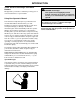
INTRODUCTION Introduction Thank You for Purchasing a John Deere Product We appreciate your business and wish you many years of safe and satisfied use of your machine. cCAUTION: Avoid injury! This symbol and text highlight potential hazards or death to the operator or bystanders that may occur if the hazards or procedures are ignored. Using Your Operator’s Manual IMPORTANT: Avoid damage! This text is used to tell the operator of actions or conditions that might result in damage to the machine.
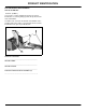
PRODUCT IDENTIFICATION Product Identification Record Identification Numbers 42-Inch Snowblower Serial No. (010001-) If you need to contact an Authorized Service Center for information on servicing, always provide the product model and serial number. You will need to locate the model and serial number for the machine and for the engine of your machine and record the information in the spaces provided below.
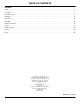
TABLE OF CONTENTS Table of Contents Contents Safety . . . . . . . . . . . . . . . . . . . . . . . . . . . . . . . . . . . . . . . . . . . . . . . . . . . . . . . . . . . . . . . . . . . . . . . . . . . . . . . . . . . . . . . . . . .1 Assembly . . . . . . . . . . . . . . . . . . . . . . . . . . . . . . . . . . . . . . . . . . . . . . . . . . . . . . . . . . . . . . . . . . . . . . . . . . . . . . . . . . . . . . . .4 Preparing Vehicle . . . . . . . . . . . . . . . . . . . . . . . . . . . . . . . . . . . .
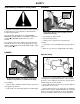
SAFETY WARNING Safety Understanding The Machine Safety Labels The machine safety labels shown in this section are placed in important areas on your machine to draw attention to potential safety hazards. On your machine safety labels, the words DANGER, WARNING, and CAUTION are used with this safety-alert symbol, (c). DANGER identifies the most serious hazards.
SAFETY • before you operate. Drive up and down-not across slopes. • DO NOT operate near edge of ditch or bank. Avoid holes, rocks, and roots. Be alert for hidden hazards. • Older adults are involved in a large percentage of riding mower accidents involving injury. These operators should evaluate their ability to operate a mower and a snowblower safely enough to protect the operator and others from serious injury. Parking Safely 1. Stop machine on a level surface, not on a slope.
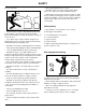
SAFETY Avoid Injury from Moving Parts Practice Safe Maintenance • Keep hands, feet and clothing away from snowblower and discharge chute when auger is turning. • • Understand service procedure before doing work. Keep area clean and dry. Stop auger when you are not throwing snow. • Stop vehicle engine before you unplug, repair, or adjust snowblower. • Never lubricate, service, or adjust machine while it is moving. Keep safety devices in place and in working condition. Keep hardware tight.
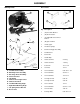
ASSEMBLY Box of Parts Assembly Identify Parts B A A D C B M95927 Qty Description 1 (A) Front Axle Bracket 3 (B) Anchor Stacks 1 (C) Adjustable Control Rod Anchor 2 (D) Spacer Shims 1 V-Belt, Upper 2 Lift Assist Springs 2 Chain and Toggle Assembly 2 Tail Reflectors 2 Clevis Pins 1 Handle Grip 2 Hair Cotter Pins 2-7/8 Lg 4 Hair Cotter Pins 1-5/8 Lg 1 Cotter Pin 1/8 x 1 1/4 2 Hex Nuts 1/2-13 6 Hex Head Bolts 5/16-18 x 1 3/4 2 Hex Head Bolts 3/8-16 x 1 2 Hex Hea
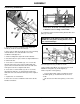
ASSEMBLY Assembling Snowblower I E D F E Picture Note: Underside of mounting frame shown to illustrate correct routing of lower V-belt. C B F A C 9. Install lower V-belt around mounting bracket idlers and pulley (I) as shown. IMPORTANT: Avoid damage! Route upper V-belt INSIDE three belt guides. Routing belt incorrectly can cause belt damage. C 1. Raise the rear of the snowblower and slide the lift handle (A) under the channel bracket (B). K J 2.
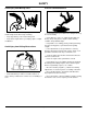
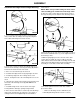
ASSEMBLY Assemble Discharge Chute to Auger Housing stack anchors. NOTE: Make sure top strand coming off chute control cable assembly goes around front of discharge chute. 9. Move the chute control cable (H) up from the stack of the auger housing onto the bottom of the discharge chute. A A M95940 D 1. Loosen 3/8-Inch nut and lock washer (A) that holds chute control cable assembly to the auger housing and move cable down away from anchor mounts. K J G B D I C M95940 10.
ASSEMBLY • If rotation difficulty continues use a screwdriver to pry out carefully on all three of the chute clips to obtain a 1/ 16 to 1/8-Inch gap between base (L) and chute clips (M) or until chute rotates freely.
PREPARING VEHICLE Install Spring Anchor Bracket to Front of Tractor Preparing Vehicle Install Tractor Weights and Chains cCAUTION: Avoid injury! The machine may become unstable when operating with snowblower. Use wheel weights to improve stability when operating with snowblower. Remove weights from tractor after snowblower is removed. NOTE: Before you attach snowblower, REMOVE MOWER DECK from tractor. (See Removing and Storing Mower section in your Tractor Operator’s Manual.) A B M95928 1.
PREPARING VEHICLE Install Mounting Angles B G H C A I D J M95930 M95932 1. Assemble 1/2-Inch standard nut (A) onto 1/2 x 2-Inch hex bolt (B) and run it down to the end of the treads. 2. Lock the nut in place with two wrenches. 8. Insert 3/8 x 1 1/4-Inch bolt (G) down through mower mounting bracket of tractor (H), through 7/16-Inch jam nut (I) used as spacer, through mounting angle, then secure with 3/8-Inch Nylock nut (J). 9.
PREPARING VEHICLE cotter pin (E). 4. Temporarily lay adjustable end of clutch link rod on top of the left side mounting angles until you are ready to attach to the snowblower. Install Reflective Tape A M95935 Apply two reflectors (A), one on each side of rear hitch plate and a minimum of 305 mm (12 in.) from the ground.
INSTALLING sliding rear slots of upper mounting frame onto 1/2 x 2-Inch bolts (B) protruding from mounting angles of tractor. Installing Place Tractor Over Snowblower Frame cCAUTION: Avoid injury! Attachment is heavy. Keep hands and feet out from under attachment when removing or installing. 1. Park machine safely. (See Parking Safely in the Safety Section). Install Upper V-Belt cCAUTION: Avoid injury! The engine may accidently start while servicing the machine.
INSTALLING Set Lower V-Belt Tension B E F A 4. Move belt guide (E) and roll upper V-belt around tractor engine drive pulley (F). Pull tensioning chain (A) to tighten lower V-belt and secure with hair cotter pin (B). Attach Lower Mounting Frame to Tractor Install Clutch Link Rod 1. Move snowblower lift bar forward to the lowered position. 2. Slide snowblower lift handle under rear of lower mounting frame and lift up to raise front mounting brackets into clevises of mounting angles. 1.
INSTALLING Install Lift Handle 6. If chain and spring are not taunt, remove the hair cotter pin, apply a little more pressure and reinstall the hair cotter pin. 7. Assemble lift assist spring on other side of tractor using the same procedure. A Install Chute Control Support C F B B A 1. Slide the lift handle (A) over the end of the lift bar (B) with the grip offset toward the operator’s position of the tractor. 2. Adjust lift height. E Install Lift Assist Springs D 1.
REMOVING Removing Removing Snowblower E cCAUTION: Avoid injury! Attachment is heavy. Keep hands and feet out from under attachment when removing or installing. NOTE: Store all hair cotter pins and clevis pins in snowblower assembly for storage. 1. Park machine safely. (See Parking Safely in the Safety Section). 4. Lower snowblower and remove lift handle (E). B F A 2. Loosen chute control support bolt (A) then remove chute control support and chute control rod (B) as one assembly. 5.
REMOVING cCAUTION: Avoid injury! When the snowblower is removed, remove any weights that were added to the tractor. J 12.Remove any weights that were installed when preparing the tractor. I 8. Roll tractor forward carefully until rear of upper mounting frame (I) can be lowered from 1/2 x 2-Inch bolts (J) in mounting angles. M95942 9. Roll tractor backward off of the snowblower. M K L M95931 10.Remove both left hand and right hand mounting angles (K) from tractor.
OPERATING Before Operating Snowblower Snowblowing Tips • Learn all controls and how they work. Read your Tractor's Operator Manual, if necessary. Install tire chains and rear weights on tractor. • STOP engine. Operate snowblower at full throttle. • LOCK park brake. Operate snowblower at safe, SLOW travel speed. • Remove key. Slow down: • Make operating adjustments as necessary. • On slopes. • Tighten loose hardware. • When you make turns.
OPERATING Adjusting Chute A B C M95958 M95964 The snowblower has a discharge radius of 240 degrees and is controlled by the chute control rod. The discharge chute stop bolt will prohibit rotation beyond this point. 3. Pull back on attachment clutch lever (A) to DISENGAGE auger. A 4. Lower snowblower to ground. 5. STOP engine. 6. LOCK park brake (B). 7. Remove key (C).
OPERATING not, repeat process. moving the snow deflector (A). To increase distance snow is discharged, pull down on snow deflector control handle (B) and lock in position. Adjusting Lift Assist Springs Adjusting Lift Height cCAUTION: Avoid injury! Rotating auger is dangerous. cCAUTION: Avoid injury! Rotating auger is dangerous. Before making adjustment: • Park the machine safely and lock the park brake before getting off the seat.
OPERATING used on rough surfaces, increase tension on lift assist spring by removing hair cotter pin and pulling several links up through hole in spring anchor bracket and replacing hair cotter pin. A 3. Adjust chain and toggles evenly. Adjusting Skid Shoes cCAUTION: Avoid injury! Rotating auger is dangerous. M95957 4. Loosen six nuts (A) on the inside of the auger housing which secure the skid shoes.
OPERATING Operating Snowblower cCAUTION: Avoid injury! Thrown objects can be dangerous. Before you operate snowblower: Clear area of bystanders and pick up objects which may be thrown by snowblower. A B 1. Turn discharge chute control rod to desired direction of discharge. 2. Move snow deflector to desired discharge distance. 3. Start engine. C M95964 1. STOP tractor. 2. Pull back on attachment clutch lever (A) to DISENGAGE. A 3. STOP the engine. 4. LOCK the park brake (B). 5. Remove the key (C). 6.
OPERATING 2. LOWER snowblower to trailer deck. 3. STOP engine. 4. LOCK park brake. 5. Fasten tractor and snowblower to deck with straps, chains, or cables. 6. Trailer must have lights and signs required by law.
REPLACEMENT PARTS Replacement Parts Service Literature If you would like a copy of the Parts Catalog or Technical Manual for this machine call: • U.S. & Canada: 1-800-522-7448. • All Other Regions: Your John Deere dealer. Parts WE RECOMMEND quality parts and lubricants, available at your Authorized Service Center. PART NUMBERS MAY CHANGE, use part numbers listed below when you order. If a number changes, your service center will have the latest number.
SERVICE Service Service Intervals Before Each Use Check unit for loose fasteners. Lubricate discharge chute. Every 10 Hours or Each Year Lubricate all zerks. Lubricate auger bearings. Lubricate discharge chute. Lubricate lift bar. Check and adjust lift height. Check skid shoes and scraper blade and replace if necessary. Check V-belts and replace if worn. Check snow auger and straighten if necessary. As Required Check discharge chute drive tube. Check lift assist springs. Check skid shoes.
SERVICE Lubricate Auger bolt (A). B B B A C A Lubricate auger bearings (A), auger tubes (B), and discharge fan (C) with General Purpose Grease. M95959 • Tighten lock nut (B) 1/8 turn and check rotation of discharge chute drive tube by turning chute control rod. Lubricate Discharge Chute • A small amount of resistance should be encountered. DO NOT overtighten. Tighten until discharge chute holds its position.
SERVICE IMPORTANT: Avoid damage! Route upper V-belt INSIDE three belt guides. Routing belt incorrectly can cause belt damage. B A B K B B 2. Remove the drive pulley guard (B) from the auger housing. 4. Check belt routing. Make sure that upper V-belt is routed INSIDE the clutch idler pulley (A) and three belt guides (B). 5. Reassemble snowblower to the tractor. 3. Roll lower V-belt off of jack shaft pulley, idlers and mounting bracket pulley and remove it from the snowblower.
SERVICE E Picture Note: Underside of mounting frame shown to illustrate correct routing of lower V-belt. 5. Assemble new lower V-belt around mounting bracket pulley and idlers (E) as shown. 6. Install the drive pulley guard to the rear of the auger housing. 7. Set lower V-belt tension.
TROUBLESHOOTING Troubleshooting Using Troubleshooting Chart If you are experiencing a problem that is not listed in this chart, see your authorized service center dealer for service. When you have checked all the possible causes listed and you are still experiencing the problem, see your authorized service center. IF CHECK Auger Housing Vibration Failed bearing. (See your Authorized Service Center.) Lower V-Belt Fluttering Lower V-belt too loose. No grease on J-shaft housing zerk.
STORAGE Storage Storing Snowblower Remove snowblower from tractor. Clean the snowblower with standard garden hose. Check V-belts, snow auger chain, scraper blade, and skid shoes and replace if worn. Do not install new belts until you take snowblower out of storage. If possible, store snowblower indoors on hard, level surface. If you store snowblower outside: • Put blocks or a board under snowblower. • Cover snowblower with a waterproof cover. Inspect snowblower.
INDEX Index A Angles, Install Mounting ........................................9 Auger, Lubricate ...................................................24 B Battery, Check Tractor Engine Oil and ...................8 Bell Crank, Install Clutch Link Rod to Clutch .....12 Belt, Install Upper .................................................11 Belt, Replacing Lower ..........................................25 Belt, Replacing Upper ...........................................24 Belt, Set Lower V-belt Tension ......
INDEX T Tape, Install Reflective .........................................10 Tire Pressure, Check ...............................................8 Transporting ..........................................................20 Troubleshooting Chart ..........................................27 W Weights and Chains, Install Tractor ........................
QUALITY STATEMENT Quality Statement Your product, designed and built by John Deere, is more than just a purchase, it’s an investment in quality. That quality goes beyond our equipment to your dealer’s parts and service support. That’s why John Deere has initiated a process to handle your questions or problems, should they arise. If you have questions or problems with your new product, please follow the steps below.