DCY iGuide OPERATOR’S MANUAL iGuide OMPFP10808 ISSUE J0 (ENGLISH) CALIFORNIA Proposition 65 Warning Diesel engine exhaust and some of its constituents are known to the State of California to cause cancer, birth defects, and other reproductive harm. If this product contains a gasoline engine: WARNING The engine exhaust from this product contains chemicals known to the State of California to cause cancer, birth defects or other reproductive harm.
Introduction www.StellarSupport.com NOTE: Product functionality may not be fully represented in this document due to product changes occurring after the time of printing. Read the latest Operator’s Manual and Quick Reference Guide prior to operation. To obtain a copy, see your dealer or visit www.StellarSupport.com OUO6050,0000FB1 1910AUG101/1 Foreword WELCOME to the GreenStar™ system offered by John Deere. READ THIS MANUAL carefully to learn how to operate and service your system correctly.
Contents Page Page Safety .......................................................... 051 Unified Inch Bolt and Screw Torque Values........402 Getting Started Theory of Operation............................................101 Making Implement Guidance Function ...............102 Accuracy.............................................................102 iGuide Activation.................................................103 Useful Buttons and Icons....................................
Contents ii 102110 PN=2
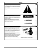
Safety Recognize Safety Information Follow recommended precautions and safe operating practices. T81389 —UN—07DEC88 This is a safetyalert symbol. When you see this symbol on your machine or in this manual, be alert to the potential for personal injury. DX,ALERT 1929SEP981/1 Understand Signal Words DANGER or WARNING safety signs are located near specific hazards. General precautions are listed on CAUTION safety signs. CAUTION also calls attention to safety messages in this manual.
Safety Park Machine Safely • Lower all equipment to the ground. • Stop the engine and remove the key. • Disconnect the battery ground strap. • Hang a "DO NOT OPERATE" tag in operator station. TS230 —UN—24MAY89 Before working on the machine: DX,PARK 1904JUN901/1 Prepare for Emergencies Be prepared if a fire starts. Keep emergency numbers for doctors, ambulance service, hospital, and fire department near your telephone. TS291 —UN—23AUG88 Keep a first aid kit and fire extinguisher handy.
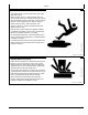
Safety Practice Safe Maintenance Understand service procedure before doing work. Keep area clean and dry. Never lubricate, service, or adjust machine while it is moving. Keep hands, feet , and clothing from powerdriven parts. Disengage all power and operate controls to relieve pressure. Lower equipment to the ground. Stop the engine. Remove the key. Allow machine to cool. Securely support any machine elements that must be raised for service work. Keep all parts in good condition and properly installed.
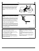
Safety Keep Riders Off Machine Only allow the operator on the machine. Keep riders off. TS290 —UN—23AUG88 Riders on machine are subject to injury such as being struck by foreign objects and being thrown off of the machine. Riders also obstruct the operator’s view resulting in the machine being operated in an unsafe manner.
Getting Started Theory of Operation iGuide is a passive implement guidance system which allows a machine to be driven in such a way as to keep the implement on its desired track. It is able to do this with a StarFire™ GPS receiver on both the machine and the implement.
Getting Started Making Implement Guidance Function Implement Guidance will work with pull type implements only.
Getting Started • iGuide Order Number • GreenStar display Serial Number • GreenStar display Challenge Code iGuide Activation See GreenStar Display Operator Manual for activating. To activate iGuide, please visit www.StellarSupport.com or call our Customer Contact Center with the following items in hand: CZ76372,00001CB 1912OCT101/1 PC8663 —UN—05AUG05 Useful Buttons and Icons The MENU Softkey allows access to all display applications. The MENU Softkey will be on every display screen.
Getting Started Use the STARFIRE IMPLEMENT Softkey to setup the implement Receiver and start the TCM calibration for this receiver. The Serial Number of the receiver is shown on this button. PC9966 —UN—09FEB07 NOTE: The implement receiver must be a StarFire iTC. STARFIRE IMPLEMENT Softkey CZ76372,00001CC 1912OCT105/11 PC12947 —UN—12OCT10 Press the GUIDANCE Softkey to input required information on desired Guidance Operation.
Getting Started Use Offset Toggle button to toggle lateral offset from left to right and vice versa. PC10846 —UN—07DEC07 Offset Toggle Button CZ76372,00001CC 1912OCT1010/11 PC11041 —UN—19FEB08 Machine icon on guidance screen represents the location of the machine. Implement icon on guidance screen represents the location of the implement. Guidance reference point on guidance screen represents the location of the guidance point for the system.
Setup • Guidance Setting—Tracking mode, Implement Getting Started Guidance Mode, and iGuide settings These items can be set up separately or the Setup Wizard can be used by checking the Implement Guidance option (M). To access the Setup Wizard, select Softkey (F) (GreenStar).
Setup PC8663 —UN—05AUG05 Machine Setup MENU >> GREENSTAR >> EQUIPMENT allows access to MACHINE and IMPLEMENT setup screens.
PC10802 —UN—08JUL08 Setup Machine Tab A—Machine Tab B—Implement 1 Tab C—Machine Type DropDown Menu D—Machine Model DropDown G—Machine Turn Radius J— Recording Source DropDown Menu InputBox Menu E—Machine Name DropDown H—Turning Sensitivity InputBox K—Record/Pause Button Menu I— Change Offsets Button L— Enable Monitoring Without F— Connection Point DropDown GPS Check Box Menu NOTE: Machine name must be defined in order to change offsets. All offsets will be saved under the current machine name.
Setup PC8663 —UN—05AUG05 Machine Offsets Change Offsets MENU >> GREENSTAR2 PRO Softkey >> EQUIPMENT Softkey MENU Softkey PC12685 —UN—14JUL10 Press CHANGE OFFSET button on Machine Setup screen.
Setup InLine distance from nonsteering axle to GPS receiver (B) will be • Row crop tractors—rear axle • Articulated tractors—front axle • Track tractors—rear axle NOTE: Offset (B) for track tractors should be measured from the receiver to the pivot point. Offset Toggle button (E) toggles the receiver from the left side of machine to the right side.
Setup PC8663 —UN—05AUG05 Implement Setup NOTE: The implement setup should be verified before operating iGuide.
PC11178 —UN—14JUL08 Setup Implement Tab A—Machine Tab B—Implement 1 Tab C—Implement 2 Tab D—Implement Type DropDown G—Change Offsets Button Menu H—GPS Offsets Button E—Implement Model DropDown I— Change Widths Buttons Menu F— Implement Name DropDown Menu Press Implement 1 tab to get to the implement setup page. NOTE: All offsets including GPS offsets on the implement will be stored to the implement name. The name will also be the base for transferring data to the desktop software.
Setup Implement Offsets Press CHANGE OFFSET button on Implement Setup screen. Implement name must be defined to save implement offsets. Implement Offsets—Used to define the actual implement position relative to the machine. Control Point—The location around which the implement rotates. Enter Implement Offsets: • A) Inline distance from connection point to front of • PC11838 —UN—20MAR09 • implement. On pulltype implements, think of this as the tongue.
Setup Change Widths—Used to enter implement width and track spacing for guidance. Change implement width and track spacing when changing implements. Implement width and track spacing are independent of each other. NOTE: IMPLEMENT tab will show HEADER for Combines, ROW UNITS for Cotton Pickers, and BOOM for Sprayer. PC11072 —UN—29FEB08 NOTE: Implement width may come from certain controllers such as SeedStar. Defining Implement Width and Track Spacing.
Setup Implement GPS Offsets Press GPS OFFSET button on Implement Setup screen. This button will only be active if an implement GPS receiver is connected to the CAN Bus. Enter Implement GPS Offsets: IMPORTANT: Drive a vehicle forward and have the vehicle & implement in a straight line before measuring and calculating these dimensions. This is very important for accurate measurements.
Setup PC11843 —UN—23MAR09 Receiver Installation Possible Mounting Location A—Connection Point B—Control Point The mounting example diagram has a distance of 10 m (32.8 ft) from the connection point (A) to the control point (B). with the maximum of 2 m (6.6 ft) to left or right from center gives possible mounting location (dark shaded portion in example diagram). The minimum distance needed between the connection point and the GPS receiver of 2 m (6.
Setup PC8663 —UN—05AUG05 GPS Receiver Setup MENU >> STARFIRE iTC Implement >> SETUP tab allows access to StarFire iTC setup on the implement. NOTE: The implement receiver will detect its position automatically when it is attached to the implement receiver application harness. If there is no implement receiver shown on the CAN bus, check implement harness connection. MENU Softkey PC9966 —UN—09FEB07 NOTE: Original StarFire receivers cannot be used on the implement or machine for iGuide.
PC11844 —UN—23MAR09 Setup StarFire iTC Implement—Main A—Info Tab B—Setup Tab C—Activations Tab D—Serial Port Tab E—Correction Mode DropDown Menu F— Correction Default CheckBox G—Mount Direction DropDown Menu H—Fore/Aft InputBox I— Height InputBox M—TCM On/Off Toggle Button J— Enable Optimize Shading N—TCM Calibrate Button CheckBox K—Enable QuickStart CheckBox L— Hours On After Shutdown DropDown Menu Select Correction Mode to match the desired correction mode.
Setup Enter the correct receiver height above the ground. To measure the receiver height, put the implement at its working depth (if possible) and measure the height. If this is not possible, lower the implement to the ground, and subtract the desired working depth to get the value to be entered. Example: 2210 field cultivator—Lower the implement so the sweeps are on the ground. Measure the height from the ground to the top of the receiver.
Setup PC11066 —UN—29FEB08 TCM Calibration TCM Calibration A—Implement with one main axle B—Implement with carrying wheels at the front and rear One of the most important steps in making iGuide function at its peak performance is the TCM Calibration for both the machine and implement. If the TCM calibration is not performed correctly then a bias could occur in the machine, implement or both. A bias is when the machine AutoTracs down and back on the same path and the wheel tracks do not line up.
Setup Adjusting Lateral Offsets If TCM’s have been properly calibrated and machine or implement still cannot track on same line going both directions, a lateral offset should be entered. 1. The offset will be half the distance the two paths were offset and in the same direction. 2. When entering lateral offset for implement, enter a GPS offset on GPS offsets page. 3. Remember, when looking at tracks on the ground, machine and implement must be symmetrical.
Setup PC8663 —UN—05AUG05 Guidance Setup Guidance Setup MENU >> GREENSTAR >> GUIDANCE softkey >> GUIDANCE SETTINGS tab (A) MENU button PC12685 —UN—14JUL10 Select desired Tracking Mode first (refer to AutoTrac Operators Manual). If Curve Track was selected, check Curve Track settings. Set Implement Guidance Mode (B) to iGuide. Select iGuide Settings (C) to define Slope Compensation and iGuide sensitivity.
Setup Recommendation for use: • Unless the field is completely flat, the slope compensation value can aid in keeping the implement on line. • 02 degrees—Slope compensation may not be needed. Recommended starting value 1.3 cm (0.5 in.)/degree. • 25 degrees—Slope compensation provides a moderate amount of machine correction and is recommended to be turned on. Typical values of 1.3 to 3.8 cm (0.5 to 1.5 in.)/degree. • 5 degrees and above—Slope compensation is recommended to be on.
Setup CZ76372,00001DD 1912OCT103/6 PC11794 —UN—09MAR09 The slope compensation can be calibrated rather than manually entered. 1. iGuide must be active to calibrate 2. Calibrate at operating speed and with implement at operating depth 3. Do not calibrate when Roll angle is less than 2 degrees Direction of roll angle may change On tight curves A line acquisition is occurring 4. Slope compensation may not be required on slopes less than 5 degrees 5.
PC11062 —UN—29FEB08 Setup 10 Degree Slope Compensation A—Up Hill B—Down Hill E—Implement F— Desire Path C—25.4 cm (10 in.) D—Tractor G—Implement Drift Path • iGuide Sensitivity allows the system to respond to Calculating Slope Compensation Manually If the center of the machine and center of the implement positions are 25.4 cm (10 in.) apart on a slope with a roll angle of 10 degrees, the slope compensation value should be set to 2.54 cm (1 in.) per degree (25.4 cm (10 in.
Operation PC8663 —UN—05AUG05 Operation of iGuide MEMU >> GREENSTAR >> GUIDANCE allows access to Guidance Settings and Shift Track Settings.
PC11899 —UN—01APR09 Operation GreenStar—Guidance A—View Tab B—Guidance Setting Tab C—Shift Track Settings Tab D—iTEC Pro Tab E—Path Accuracy Indicator F— Shift Track Left Button G—Shift Track Center Button H—Shift Track Right Button I— Steer Sensitivity InputBox J— Set Track 0 Button K—iGuide Status Pie L— Steer On/Off button M—iTEC Pro Status Pie N—iTEC Pro Enable Button O—iTEC Pro Icon P—Implement Receiver Location Icon In order to operate iGuide, a valid setup must be available (see APPENDIX—VALID
Integrating iGuide and iTEC Pro Hardware and Software Requirements In order to run iTEC Pro and iGuide simultaneously, the following hardware and software are required: 1. 2. 3. 4. Both receivers must be iTC receivers RTK GPS signal level on both receivers Vehicle must have integrated AutoTrac components GreenStar 2 2600 display must have AutoTrac SF2 activation 5. GreenStar 2 2600 display must have iGuide and iTEC Pro software activation 6.
Integrating iGuide and iTEC Pro PC11845 —UN—23MAR09 Operation GreenStar—Guidance A—View Tab B—Guidance Setting Tab C—Shift Track Settings Tab D—iTEC Pro Tab E—Path Accuracy Indicator F— Shift Track Left Button G—Shift Track Center Button H—Shift Track Right Button 1. Tracking Mode—The operation of iGuide and iTEC Pro will be available only on straight tracking mode. 2. End of Turn Performance a. When both systems are activated, the operator will see two paths on the screen. b.
Integrating iGuide and iTEC Pro Using Implement Receiver for Documentation and Coverage Map When using iGuide guidance mode, the documentation and coverage map will use the implement receiver position as a reference point. When iGuide is not in use and the implement receiver is connected to the CAN bus, the system will use the implement receiver position for documentation and coverage map purposes.
Tuning Guide Setting Up Vehicle Offsets Vehicle Offsets Offsets “A”, “B”, “C”, and “D” are critical for iGuide to operate efficiently.
Tuning Guide Setting Up Implement Offsets Implement Offsets Offsets “A”, “B”, and “D” are critical for iGuide to operate efficiently. Offset “E” is not required for iGuide. NOTE: Offset “C” is required when using a non centered implement. E—Inline distance from connection point to connection point for second implement. Value only needed if second implement is used. F— Offset Toggle Button G—A+B Documentation/Swath Control location when in use.
Tuning Guide Offset “C” should match Receiver Height from Implement Receiver softkey. PC9966 —UN—09FEB07 StarFire iTC Implement Softkey CZ76372,00001E2 1912OCT102/3 PC12219 —UN—19AUG09 Check the GreenStar Display for correct inline distance between vehicle receiver and implement receiver.
Tuning Guide Tuning Slope Compensation Typical Value Slope Range Degree Cm/Degree 0—2 1.3 0.5 2—5 1.3—3.8 0.5—1.5 Greater Than 5 2.0—8.9 0.8—3.5 Inches/Degree • 0—2 degrees Slope Compensation may not be needed • 2—5 degrees Use of Slope Compensation is • PC12220 —UN—27AUG09 Slope Compensation works as a lookahead for the vehicle. Slope Compensation helps aids in moving the vehicle up the hill to keep the implement on the guidance line.
Troubleshooting Troubleshooting Tips 1. Implement receiver not showing up in the GreenStar Display Check if Constant Power Extension harness (PF90550 or PF90551) is installed. Check for latest software (version 2.3.1385 or higher) on Implement Receiver. Check if receiver is receiving Switched, Unswitched, CAN Low and CAN High power. Check machine fuse panel for blown fuses 2. Implement GPS loses RTK signal more often than machine receiver Check antenna on GPS receiver for tight connection.
Troubleshooting Always verify correct implement dimensions when using the “out of box” dimensions from the GreenStar Display or Apex. CZ76372,00001E3 1912OCT102/2 Valid Configuration iGuide requires certain settings to be available and certain offsets need to be within a defined range. If one of these constraints is not given, tracking cannot be activated. For a new, unknown implement, all offset will be zero as a default. General constraints: • Will not work with 3pt implements.
Specifications Metric Bolt and Screw Torque Values TS1670 —UN—01MAY03 Bolt or Screw Size M6 4.8 8.8 9.8 10.9 12.9 12.9 4.8 8.8 9.8 10.9 12.9 12.9 Class 4.8 Lubricateda N∙m 4.7 lbin 42 Class 8.8 or 9.8 Dryb N∙m 6 Lubricateda lbin 53 N∙m 8.9 lbin 79 Class 10.9 Dryb N∙m 11.3 Lubricateda lbin 100 N∙m 13 N∙m M8 11.5 102 14.5 N∙m M10 23 N∙m 204 128 lbft 29 21 22 N∙m 43 194 lbft 32 27.5 N∙m 55 243 lbin 115 lbft Class 12.9 Dryb N∙m 16.
Specifications Unified Inch Bolt and Screw Torque Values TS1671 —UN—01MAY03 Bolt or SAE Grade 2a SAE Grade 1 Lubricatedb Screw Size N∙m 1/4 3.7 lbin 33 Dryc N∙m 4.7 Lubricatedb lbin 42 N∙m 6 lbin 53 SAE Grade 5, 5.1 or 5.2 Dryc N∙m 7.5 Lubricatedb lbin 66 N∙m 9.5 lbin 84 SAE Grade 8 or 8.2 Dryc N∙m 12 Lubricatedb lbin 106 N∙m 13.5 N∙m 5/16 7.7 68 9.8 86 12 106 15.5 137 19.5 N∙m 3/8 13.5 120 17.
Index Page Page A S APPENDIX Valid Configuration.................................................. 352 C Setup Getting Started........................................................ 151 Sofware and Settings ................................................. 101 T Control Point............................................................... 158 G Getting Started ........................................................... 151 iGuide Activation .....................................................
Index Index2 102110 PN=2
John Deere Service Keeps You On The Job John Deere Parts We help minimize downtime by putting genuine John Deere parts in your hands in a hurry. TS100 —UN—23AUG88 That’s why we maintain a large and varied inventory—to stay a jump ahead of your needs. JS56696,0000239 1908FEB081/1 The Right Tools TS101 —UN—23AUG88 Precision tools and testing equipment enable our Service Department to locate and correct troubles quickly . . . to save you time and money.