OPERATOR’S MANUAL ROTARY CUTTERS RC1048 RC1060 RC1072 ME300309 (Rev.
DEALER PREPARATION CHECK LIST Frontier 10 Series Rotary Cutter THIS CHECKLIST IS TO REMAIN IN OWNER’S MANUAL It is the responsibility of the dealer to complete the procedures listed below, then review this checklist with the customer upon the delivery or the sale of this implement. 1. Implement is completely assembled. 2. Gearbox filled with oil and checked for possible leaks. (See page 29) 3. All fittings lubricated. (See page 20 - 21) 4. All shields in place and in good condition. 5.
TO THE DEALER: Assembly and proper installation of this product is the responsibility of the Frontier dealer. Read manual instructions and safety rules. Make sure all items on the Preparation Check List in the Operator’s Manual are completed before releasing equipment to the owner. The dealer must complete the Product Registration form, located on the Frontier website. Failure to complete and return the form does not diminish customer’s warranty rights.
TABLE OF CONTENTS Introduction..................................................................................................... 4 Safety ..........................................................................................................5-9 Description .............................................................................................. 10-11 Preparation ............................................................................................. 12-13 Attaching ..........................
! SAFETY RULES ATTENTION! BECOME ALERT! YOUR SAFETY IS INVOLVED! ! Safety is a primary concern in the design and manufacture of our products. Unfortunately, our efforts to provide safe equipment can be wiped out by an operator’s single careless act. In addition to the design and configuration of equipment, hazard control and accident prevention are dependent upon the awareness, concern, judgment, and proper training of personnel involved in the operation, transport, maintenance and storage of equipment.
! SAFETY RULES ATTENTION! BECOME ALERT! YOUR SAFETY IS INVOLVED! (Safety Rules continued from previous page) Make sure all safety decals are installed. Replace if damaged. (See Safety Decals section for location.) Make sure shields and deflectors are properly installed and in good condition. Replace if damaged. Inspect and clear area of stones, branches, or other hard objects that might be thrown, causing injury or damage. • Transportation Power unit must be equipped with ROPS or ROPS cab and seat belt.
! SAFETY RULES ATTENTION! BECOME ALERT! YOUR SAFETY IS INVOLVED! Stop power unit and equipment immediately upon striking an obstruction. Turn off engine, remove key, inspect, and repair any damage before resuming operation. Leak down or failure of mechanical or hydraulic system can cause equipment to drop.
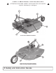
! SAFETY and INSTRUCTIONAL DECALS ATTENTION! BECOME ALERT! YOUR SAFETY IS INVOLVED! Replace Immediately if Damaged! ! 1 6 5 2 4 3 RC1060 WITH LAMINATED TAILWHEEL 8 9 5 7 RC1060 WITH SOLID RUBBER TAILWHEEL 8 Safety and Instruction Decals
! SAFETY and INSTRUCTIONAL DECALS ATTENTION! BECOME ALERT! YOUR SAFETY IS INVOLVED! Replace Immediately if Damaged! 3 540 RPM PN - ME100192 Warning Label Sheet Part Number TIFC711209 (Contains Label #'s 1,2,3,6,7,8,9 ! OIL 8 NEEDS PN - ME100197 (2 needed) 5 REDPNREFLECTOR - ME100195 OBJECT 9 THROWN PN - ME100189 5TIFC711207 4 1 SERIAL NUMBER RAISE CUTTER PN - ME100190 7 2 ENTANGLEMENT PN - ME100191 6 RAISE CUTTER PN - ME100194 THROWN OBJECT PN - ME100193 Safety and Instruction Decals 9
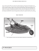
GENERAL DESCRIPTION Your 10 Series Frontier Rotary Cutter has been carefully designed for cutting grass and small brush. This manual is provided to give you the necessary operation and maintenance instructions for keeping your rotary cutter in excellent operating condition. Please read this manual thoroughly. Understand the purpose of the controls and how to use them. Observe all safety precautions on the machine and as noted throughout this manual.
TECHNICAL DESCRIPTION Model RC1048 RC1060 RC1072 60 inches 72 inches 1.5 to 9 inches 1.5 to 9 inches 1.5 to 9 inches up to 1 inch up to 1 inch up to 1 inch 7.5 inches 7.5 inches 7.5 inches 18 - 45 20 - 65 25 - 65 540 540 540 iMatch or Non-iMatch iMatch or Non-iMatch iMatch or Non-iMatch 1, adaptable to 2 1, adaptable to 2 1, adaptable to 2 Overall Width, in. 51.4 63.1 75.6 Overall Length, in. 86.6 98.4 110.
PREPARATION • Selecting Tractor PTO Speed IMPORTANT: Never operate a cutter equipped for 540 rpm PTO drive with a factor equipped to 1000 rpm PTO. Always run tractor at rated PTO speed. Overspeed will cause damage to drive system. Refer to your tractor Operator’s Manual to change PTO stub shaft, if necessary. • Positioning Drawbar IMPORTANT: To prevent damage to the driveline, remove, shorten, or place drawbar to one side. If equipped with clevis, remove it.
PREPARATION • Installing Hitch Pin Bushings for Category 1 Quick Coupler Hitch NOTE: Install bushings on both hitch pins. Right-hand side shown. Use Frontier category 1 quick coupler bushing kit WS862500 or John Deere category 1 quick coupler bushing kit BW15056. 1. If using John Deere bushing kit BW15056, install bushing (A) over hitch pin with cross hole as shown. 2. Install bushing (B) as shown. 3. Align holes in bushings with hole in hitch pin and install roll pin (C).
ATTACHING • Attaching Cutter to Tractor with Quick Coupler Hitch ! CAUTION: To avoid bodily injury or machine damage whenever an implement is attached, put transmission in PARK position and check the full range of hitch for interference, binding, or PTO separation. Do not stand between tractor and implement. 1. Slowly push hitch control lever to lower hitch until quick coupler hooks are lower than cutter hitch pins. 2. Back up tractor to cutter hitch. 3.
ATTACHING • Assembling PTO Driveline Telescoping Members (If Necessary) 1. Apply multipurpose grease around outside surface of inner driveline tube (A). 2. Align driveline halves and assemble telescoping members together. 3.Apply multipurpose grease, or equivalent, to all lubrication fittings before operating. (See Lubrication and Maintenance section.) A A-Inner Driveline Tube • Attaching PTO Driveline ! DANGER Shut off tractor engine before attaching PTO driveline.
ATTACHING (continued from previous page) 4. Shorten center link or lengthen lift links to provide clearance. (See your tractor Operator’s Manual.) IMPORTANT: PTO driveline may be too long for some tractor models, causing tractor transaxle damage. Hold driveline sections parallel to each other and check for a minimum of 6 inches overlap. 5. Raise and lower cutter slowly to check for binding or interference. Check cutter-to-tractor driveline telescoping length to ensure it does not bottom out.
DETACHING • Tractor with Quick Coupler Hitch 1. Raise both latch control levers on quick coupler (A). 2. Start tractor engine. 3. Lower cutter to the ground. Continue lowering quick coupler until hooks clear cutter hitch pins. 4. Carefully drive tractor away. • Tractor with Three-Point Hitch 1. Remove quick-lock pins from hitch pins and install in storage position on tractor draft links. 2. Remove and lower tractor draft links from hitch pins. 3. Disconnect center link from mast straps.
OPERATION • Adjusting Cutting Height and Angle ! DANGER Help prevent bodily injury or death caused by entanglement in rotating driveline or blades. Entanglement in rotating driveline or being struck by blades can cause serious injury or death. Before making any adjustments: (51mm) lower in the front. This tilt decreases horsepower requirements and increases potential ground speed. When fine shredding is desired, adjust rotary cutter deck level or slightly lower in the rear.
OPERATION • Follow Safe Operating Procedures 1. Perform BEFORE EACH USE maintenance in the Lubrication and Maintenance section. 2. Start tractor per tractor operator’s manual. 3. Raise/lower 3-point hitch to place cutter in working position. 4. Look to be sure no one is near cutter. 5. With tractor at idle speed, slowly engage PTO drive. ! DANGER STAY CLEAR OF ROTATING DRIVELINE. DO NOT OPERATE WITHOUT DRIVELINE SHIELDS IN PLACE AND IN GOOD CONDITION.
LUBRICATION and MAINTENANCE • Lubricating and Maintaining Machine Safely ! DANGER Help prevent bodily injury or death caused by entanglement in rotating driveline or blades. Entanglement in rotating driveline or being struck by blades can cause serious injury or death. Components will be hot after operation. Let all components cool before servicing. Replace all shields after lubricating or servicing. • Maintenance Check List Perform scheduled maintenance as outlined below.
LUBRICATION and MAINTENANCE • Lubrication Before Each Use 1. Driveline Universal Joints a. Apply multi-purpose grease with a grease gun. 2. Driveline Guard b. Apply 2-3 shots of multipurpose grease with grease gun to plastic fitting. 3. Driveline Profile c. Disconnect PTO Driveline. d. Pull two sections apart. e. Apply thin coat of multi-purpose grease to inside of female section. f. Re-assemble sections. Note: Pull each section to be sure driveline and shields are securely connected.
SERVICE • Practice Safe Service Procedures ! CAUTION: To help prevent personal injury caused by unexpected movement, be sure to service machine on a level surface. Before servicing or adjusting machine connected to a tractor: 1. Lower machine to the ground. 2. Engage tractor parking brake and/or place transmission in “Park”. 3. Disengage PTO. 4. Shut off tractor engine and remove key. 5. Wait until all moving parts have stopped. 6. Disconnect PTO driveline from tractor.
SERVICE (Service continued from previous page) C B D A A shield chain (Disconnect driveline shield chain) 1/2” x 3” Gr 8 bolt A 4mm A - Gap B - Clutch Plate C - Belleville Spring D - Cap Screw Lock Nut (6 used) • Removing and Installing Driveline-Slip Clutch 1. Disconnect driveline shield chain. 2. Open access panel on shield. 3. Remove driveline assembly from gearbox output shaft by removing 1/2” x 3” Gr 8 bolt and lock nut. 4. Make repairs as necessary: a.
SERVICE • Removing and Installing Driveline-Shear Bolt 1. Disconnect driveline shield chain. 2. Bend back driveline shield cone. 3. Remove shear bolt and lock nut. 4. Push driveline onto input shaft toward gearbox and remove snap ring. 5. Pull driveline from gearbox shaft. 6. Replace or repair as necessary. 7. Install in reverse order of removal. Snap Ring • Replacing Driveline Shear Bolt IMPORTANT: Avoid shear bolt failure at start up by engaging the PTO slowly at low engine rpm. If shear bolt fails: 1.
SERVICE • Replacing Blades IMPORTANT: Operating with loose blade hardware will damage the blade pan and blades. Whenever the blades have been removed or replaced, blade hardware MUST also be replaced. Always use genuine Frontier parts. Check blade hardware torque after one hour of operation and every eight (8) hours thereafter. NOTE: Suction blades have cutting edge on one side only. Note blade rotation when installing blades. (See DIRECTION OF BLADE ROTATION in this section.
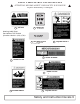
SERVICE • Replacing Blade Pan 1. Remove the blades. (See Replacing Blade in this section.) 2. Remove cotter pin from output shaft of the gearbox. 3. Loosen castle nut to the bottom of the output shaft (A). Do not remove castle nut as it must hold the blade pan when it becomes loose. 4. Tap with a hammer around the hub using a block of wood as shown in photo. 7. To reinstall blade pan, reverse the above steps. Be sure to tighten the castle nut and replace the cotter pin. 8. Replace blades.
ASSEMBLY • Perform Predelivery Service Safely ! CAUTION: Understand the predelivery procedure before doing the work. During the assembly, test, and adjustment procedures, it may be necessary to operate drives and hydraulic systems. Stay clear of machine elements when raising or lowering machine and during operation of drivelines. Practice good communication with other service technicians. Be aware of their actions and alert them to potential hazards.
ASSEMBLY • Assemble Hitch 1. Rotate hitch up. 2. Install hitch pivot bushing, bolt, lock nut and tighten. 6. Repeat on opposite brace. 7. Tighten all link and brace hardware (A). Rotate Hitch Up A IMPORTANT: Please do not over tighten hardware. IMPORTANT: Please do not over tighten hardware. 3. Attach lift arm brace to frame using 1/2” x 13/4” bolt, bushing, washers and lock nut. a. iMatch Hitch Install bolt, bushing, and lock nut into hole and tighten to specifications. (A) see photo below b.
ASSEMBLY • Install Tailwheel • Fill Gearbox 1. If necessary, attach using axle bolt, castle nut, and cotter pin. 2. Tighten hardware. IMPORTANT: Cutter is shipped without gearbox lubricant. DO NOT operate the cutter without filling gearbox with specified amount of lubricant listed below, or gearbox will be damaged. (See Lubrication and Maintenance section). 1. Remove breather plug (A) from filler hole. 2. Fill gearbox according to initial fill with 32 ounces of EP80W-90 gear oil. • Install Driveline 1.
ASSEMBLY • Install Front Deflector-Rubber (If Equipped) • Install Rear Deflector-Chains (If Equipped) IMPORTANT: Install hardware with lock nuts and flat washers on the outside of cutter. IMPORTANT: Install hardware with lock nuts and flat washers on the outside of cutter. 1. Install deflector using two (2) foot guards (See INSTALL FOOT GUARDS in this section) and provided bolts, flat washers, and lock nuts. Insert bolts and flat washer from inside out of rotary cutter. 2.
ASSEMBLY Final Inspection and Adjustments IMPORTANT: PTO driveline may be too long for some tractor models, causing tractor transaxle damage. Modify driveline if necessary. Attach rotary cutter to tractor and check cutter-to-tractor driveline telescoping length clearance. (See CHECKING DRIVELINE/CUTTER CLEARANCE in Attaching section.) IMPORTANT: Blade hardware MUST be checked after the first hour and every eight (8) hours thereafter. Check blade hardware torque.
TORQUE SPECIFICATIONS AMERICAN Bolt Head Markings SAE Grade 2 (No Dashes) SAE Grade 5 (3 Dashes) lt B” Bo ter “ me a i D Wrench Size “A” SAE Grade 8 (6 Dashes) Proper torque for American fasteners used on manufactured implement. Recommended Torque in Foot Pounds (Newton Meters).* WRENCH SIZE(IN.)”A” BOLT DIAMETER (IN.
TROUBLESHOOTING GUIDE Problem Possible Cause Possible Remedy Leaves a streak of uncut or partially cut grass. 1. Rotary cutter not level, side to side. Level 3-pt hitch linkage on tractor. 2. Blade dull or bent. Sharpen or replace blades. 3. Blades unable to cut that part of grass pressed by path of tractor tires. Slow ground speed of tractor but keep engine running at full PTO rpm. Cutting lower will help. 4. Possible build up of material under rotary cutter. Clean rotary cutter.
Item Number 1 Ship Qty. Part Number 1 5TIFC711287 1 1 5TIFC711286 1 1 5TIFC711288 2 3 3 3 4 5 5a 6 7 8 9 9 10 10 10 11 12 13 14 15 1 1 1 1 1 1 1 1 1 1 1 1 1 1 1 1 1 1 1 1 TIFC711172 ME100561 ME100562 ME100563 TIFC711111 TIFC711112 TIFC711191 ME300326 ME300277 ME300288 ME300283 ME300284 TIFC711114 TIFC711115 TIFC711116 TIFC711118 TIFC711145 TIFC711210 TIFC711211 TIFC711212 Description Deck Assembly - RC1048 (Includes gearbox, blade pan, blades, and hitch.
Item Number Ship Qty.
*Pie-cut weld Item Number Gearbox and Blade Pan Assembly Description Part Number 1 Ship Qty.
Item Number Ship Qty.
PARTS RC10 Series Shear Bolt PTO Shaft Item Number Qty. Qty.
PARTS RC10 Series Slip Clutch PTO Shaft Item Number Qty. Qty.
Item Number 1 1a 2 2a 3 4 5 6 Ship Qty.
Item Number Ship Qty.
PARTS 3-4-5 2 3-4-5 1 Chain Deflector Assembly Item Number 1 2 3 4 5 42 Parts Qty.