
Owner manual


4 - 42
3/21/97
CIRCUIT OPERATION AND DIAGNOSIS
ELECTRICAL
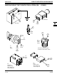
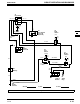
IGNITION CIRCUIT DIAGNOSIS STX38 (SN 210001— ) & STX46
When diagnosing an ignition problem, isolate magneto circuit from ground circuit by separating engine connector.
If engine will not start check magneto circuit first and then check ground circuit. If engine will not shut off, check
ground circuit. Remember engine is stopped by grounding ignition coil through either key switch, seat switch or the
brake switch and PTO switch
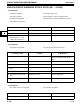
Test Conditions:
• Transaxle/hydro in neutral • PTO switch disengaged
• Brake engaged • Engine connector disconnected
• Key switch in start position • Spark plug lead connected to D05351ST Tester
Test/Check Point Normal If Not Normal
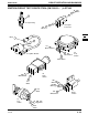
1. Spark plug Spark test indicates hot blue spark. Test ignition module.
Check armature air gap, and
flywheel magnets.
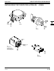
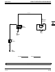
Test Conditions:
• Key switch in run position
• Meter positive (+) lead on numbered test point • Meter negative (—) lead on engine ground
Test/Check Point Normal If Not Normal
2. Engine connector 940 white
wire.
Infinite resistance Check for shorted 940/941/ 942
white wires.
Check for faulty key switch.
Check for faulty PTO switch.
Check for faulty or misadjusted
brake switch.
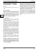
Test Conditions:
• Brake disengaged • Seat switch depressed
Test/Check Point Normal If Not Normal
3. Engine connector 940 white
wire.
Infinite resistance Check for shorted 945/946 white/
black wires.
Check for faulty seat switch.
Test Conditions:
• Key switch in off position
• Seat switch released Brake switch released
Test/Check Point Normal If Not Normal
4. Engine connector 940 white
wire .
Maximum 0.1 ohms Check for open 940/941/942 white
wires.
Check for open 100/110 black wires