
Owner manual

ELECTRICAL
CIRCUIT OPERATION AND DIAGNOSIS
4 - 58
3/21/97
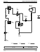
PTO CIRCUIT DIAGNOSIS STX38 (SN 210001— ) & STX46
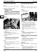
NOTE: If there excessive vibration in PTO clutch
area and noise coming from vibration between
PTO clutch and pin—see page 4-53 step 5.
NOTE: Fusible link (F1) 201 orange wire is designed
to melt internally. You cannot see that the
fusible link is bad by looking at it, test for
battery voltage at 200 red wire at key switch
terminal B to verify fusible link is good.
Test Conditions:
• Transaxle/hydro in neutral • Key switch in run position
• Brake engaged • Meter negative (-) lead on battery negative (-)
terminal
• PTO switch ON (engaged) • Meter positive (+) lead on numbered test point
Test/Check Point Normal If Not Normal
1. Battery positive terminal 11.8—13.2 volts Test battery
2. Key switch terminal B (200 red
wire).
Battery voltage Check battery cable (red)
connection, fusible link 201 orange
and 200 red wire.
3. Key switch terminal A (400
yellow wire).
Battery voltage Replace key switch (S1).
4. PTO switch 400 yellow wire. Battery voltage Test 400 yellow wire.
5. PTO switch 750 blue wire. Battery voltage Replace PTO switch.
6. PTO clutch 750 blue wire. Battery voltage Test 750 blue wire.
Test Conditions:
• Key switch in OFF position
Test/Check Point Normal If Not Normal
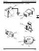
7. PTO clutch125 black wire. Maximum 0.1 ohms Check PTO clutch 125 black wire
engine ground circuit, and battery
negative cable ground connection.
Test Conditions:
• Key switch in OFF position • Disconnect PTO clutch harness connector
Test/Check Point Normal If Not Normal
8. Across PTO clutch terminals. Resistance of coil between 3 and 10
ohm.
If less than 3 or greater than 10 ohm
resistance, replace PTO clutch.