
Owner manual

3/21/97
5 - 47
POWER TRAIN
REPAIR
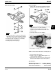
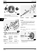
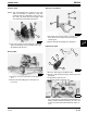
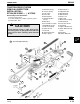
Input Shaft—Assemble
1. If new bearings (C) are used, press top bearing
flush with cover. Press lower bearing to depth of
3.43—3.81 mm (0.135—0.150 in.) inside cover.
2. Install washer (B) and O-ring (A) on shaft (D).
3. Install O-ring (F) and washer (G).
4. Install gear (H) and snap ring (I).
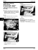
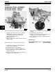
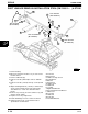
Case—Assemble
1. Fill case with John Deere Moly High Temperature
EP Grease. Transaxle capacity is 1.0 L (30 oz).
2. Apply silicone sealant and install top cover. Torque
cap screws (E) to 11.3 N•m (100 lb-in.).
3. Install ball (C), spring (B), and set screw (A).
Tighten screw one turn below flush with cover.
4. Install seal (D).
5. Turn input shaft to check for binding.
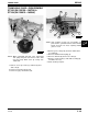
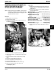
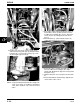
6. Install brake assembly (D).
NOTE: Correct neutral start switch is normally closed.
7. Install neutral start switch (C).
8. Install lever (B). Use LOCTITE® and tighten cap
screw to 16 N•m (144 lb-in.).
9. Install sheave (A) and snap ring on earlier models.
On later models tighten nut to 40 N•m (30 lb-ft).
Specifications:
Transaxle Cover Cap Screw . . 11.3 N•m (100 lb-in.)
Shift Lever Cap Screw . . . . . . . . . 16 N•m (144 lb-in.)
Sheave Nut (Later Models) . . . . . . . 40 N•m (30 lb-ft)
M52016
A
B
C
D
I
E
F
G
H
M52015
A
C
B
E
D
M51999
B
C
A
D