
Owner manual

3/20/97
5 - 67
POWER TRAIN
REPAIR
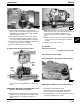
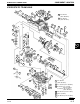
6. Turn upper case half over.
7. Install a shim washer (C) (from Shim Kit) of the
proper thickness that allows enough clearance for
E-ring (D) to be installed. “GO” air gap should be
0.25 mm (0.010 in.) or less.
8. Turn upper case half over and measure air gap
between snap ring (L) and bevel pinion gear (K)
(see Inspect Input Shaft/Pinion Gear Assembly).
9. If measurement results in a “NO GO” reading, shim
thickness (C) needs to be changed.
10. Install woodruff key (F) in shaft keyway.
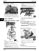
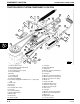
Assembly Transaxle Housing Case Halves:
1. Pack upper case beveled pinion gear and lower
case housing assembly with 638 g (1.406 lbs) of
grease.
IMPORTANT: BE SURE sealant DOES NOT contact
any gear, shaft, or bearing surfaces.
2. Apply John Deere Form-In-Place Gasket Silicone
Sealant to case cutouts where intermediate shaft
flange bearing sets into upper and lower case
halves.
3. Align lower and upper case halves together,
be
sure
shaft seals are seated correctly and you may
have to turn input shaft (D) slightly to insure
beveled pinon gear meshes with beveled drive
gear.
4. Install 14 outside socket head screws (A) and two
center socket head screws (B) with new rubber
seals (C).
5. Tighten screws to specification.
Specification:
Transaxle Cap Screws
. . . . . . . . . . . . . . . . . . . . 9—10 N•m (100—125 lb-in.)
Install Shifter Detent Assembly
STX38 (SN 210001—301382) and STX46 Transaxle
IMPORTANT: DO NOT drop or lose detent balls.
1. Install shifter shaft rubber boot (B).
2. Coat detent balls (C) and springs (D) with John
Deere Never-Seez and install in case bores.
3. Install and tighten set screws (A) until they are flush
with top of mounting hole surface.
M42313
E
C
D
F
M42318
Lower
Half
Case
Upper
Half
Case
A
M42312
D
C
B
B
A
C
D
M42316