
Owner manual

6 - 30
3/21/97
REPAIR
HYDROSTATIC POWER TRAIN
TRANSAXLE REMOVAL AND
INSTALLATION
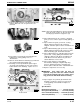
Removal
1. Safely raise and block rear of tractor off surface.
2. Safely support bottom of transaxle or have a helper
hold transaxle in place when you remove final
hardware (Steps 13—14).
3. Remove drive wheels, inspect key and keyways,
washers, and snap rings. Replace as necessary.
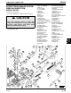
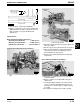
4. Remove traction drive belt (C) from drive sheave.
5. Disconnect shift linkage turnbuckle (A) from
bellcrank assembly (J).
6. Remove cotter pin and washer (K) to disconnect
brake rod from brake lever.
7. Remove chain link (O) from left-side transport valve
assembly.
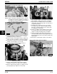
8. Remove left-front mounting bracket lower cap
screw and flange nut (F).
9. Remove flange nut (B) from right-front mounting
bracket.
10. Remove two right-side mounting cap screws and
flange nuts (L).
11. Pull transport lever (N) into over-center position to
remove two left-hand mounting cap screws and
flange nuts (M).
12. Remove transaxle to workbench.
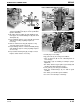
13. Remove snap ring (E) to remove shift link (D).
14. Remove cap screw and lock nut (G) to remove shift
arm (H). Inspect woodruff key and keyways of shift
arm and pump variable swashplate shifter shaft.
15. Remove flange nut (I) slowly to remove bellcrank
assembly (J).
16. Drain oil from transaxle.
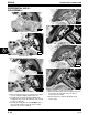
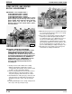
Installation
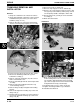
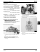
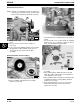
17. Make sure bellcrank assembly and transaxle right,
front mounting bracket are oriented properly. Slot
(C) should be aligned with transaxle housing rib
(A) so that ear (D) of lower anchor washer
is not
wedged behind housing vertical rib (B).
18. Install transaxle in reverse order of removal.
19. Tighten mounting hardware to specifications.
20. Install traction drive belt.
A
H
D
C
E
G
F
M58259
B
I
J
K
L
M
N
M58266
O
M58355
D
C
B
A
M58367
D
B