JLBIGGH605 Gas hob Instruction manual GB
Impor tant Saf ety Inf ormation Important Safety Information It is most important that this instruction manual should be retained with the appliance for future reference. Should the appliance be sold or transferred to another owner, or should you move house and leave the appliance, always ensure that the book is supplied with the appliance in order that the new owner can get to know the functioning of the appliance and the relevant warnings. These warnings have been provided in the interest of safety.
z z z z z z Unstable or misshapen pans should not be used on the hob as unstable pans can cause an accident by tipping or spillage. Never leave the hob unattended when cooking with oil and fats. Never use plastic or aluminium foil dishes on the hob. Perishable food, plastic items and aerosols may be affected by heat and should not be stored above or below the hob unit. This appliance is not connected to a combustion products evacuation device.
Contents Important Safety Information ............ 2 Description of the Hob ................................ 5 Instructions for the Installer ............. 6 Installation ....................................................... 6 Gas Connection ............................................. 6 Engineer technical data ................................ 7 Electrical Connections .................................. 8 Wiring diagram .............................................. 9 Fault Finding........................
Description of the Hob 2 1 3 2 4 5 1. 2. 3. 4. 5. 6. 7. 8.
Instructions for the Installer Installation IMPORTANT: This hob must be installed according to the instruction supplied, and by qualified and competent personnel to the relevant National Standards. Any gas installation must be carried out bbyy a GAS SAFE REGISTER installer installer.. The manufacturer will not accept liability, should the above instructions or any of the other safety instructions incorporated in this book be ignored.
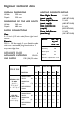
Engineer technical data HEA TING ELEMENTS RA TING HEATING RATING O VERALL DIMENSIONS Width: 590 mm Depth: 520 mm Rear Right Burner (semi rapid) Front Right Burner (semi rapid) Rear Left Burner (rapid) Front Left Burner (auxiliary) DIMENSIONS OF THE HOB C AVITY CA Width: 560 mm Depth: 480 mm SUPPL Y CONNECTIONS SUPPLY Gas: R 1/2 inch (1/2 inch male) Rear right hand corner Electric: 230 V~ 50 Hz supply, 3 core flexible cable with non rewireable plug fitted with a 3 amp cartridge fuse.
Electrical Connections Green and Yellow Blue Brown THIS HOB MUST BE EAR THED EARTHED THED.. Any electrical work required to install this hob should be carried out by a qualified electrician or competent person, in accordance with the current regulations. ) Electrical Requirements - Earth - Neutral - Live — Connect the green and yellow (earth) wire to the terminal in the plug which is marked with the letter 'E' or the earth symbol or coloured green and yellow.
Supply cable replacement The cable used to connect the hob to the electrical supply must comply to the specifications given below. Min. size Cable/flex 0.75 mm2 Cable / flex type Fuse H05 V2V2-F (T90) 3A The manufacturer declines any liability should these safety measures not be observed.
Fault Finding Pr eliminar Preliminar eliminaryy Electrical Systems Check Brown START Isolate appliance and carry out: A: Earth Continuity check. YES NO Green Blue Brown YES Green Electricity supply should now be satisfactory. Carry out: B: Insulation check. Has inlet fuse blown? NO Blue A. EAR TH CONTINUITY CHECK EARTH Appliance must be electrically disconnected meter set on W (Ohms) x 1 scale and adjust zero if necessary. a) Test leads from any appliance earth point to earth pin on plug.
Ignition System / Gas Ignition Ignitor does not spark YES Check gas supply at burner NO Check plug top fuse and replace if necessary Check polarity and earth continuity of supply point Check earth continuity of appliance Light burner manually Check by pass simmer adjusted Check position of the electrode Check fitting of burners Check continuity from the tip of each electrode to the terminals 1 to 4 on the ignitor unit Check continuity from 'N' on the mains connector block and "O" on the ignitor
Commissioning When the hob has been fully installed it will be necessary to check the minimum flame setting. To do this, follow the procedure below. z z Turn the gas tap to the MAX position and ignite. Set the gas tap to the MIN flame position then turn the control knob from MIN to MAX several times. If the flame is unstable or is extinguished follow the procedure below. Procedure: ) 1) Re-ignite the burner and set to MIN. 2) Remove the control knob.
Conversion from Natural Gas to LPG IMPORTANT: The replacement/ conversion from natural gas to LPG should only be undertaken by a competent person. It is important to note that this model is designed for use with natural gas but can be converted for use with butane or propane gas providing the correct injectors are fitted. The gas rate is adjusted to suit.
Building in IMPORTANT: This hob must be installed according to the instruction supplied, and by qualified and competent personnel to the relevant National Standards. 1 Please ensure that when the hob is installed it is easily accessible for the engineer in the event of breakdown.
Building over a kitchen unit with door Dimensions are given in mm. Proper arrangements must be taken in designing the furniture unit, in order to avoid any contact with the bottom of the hob which can be heated when it is operated. The recommended solution is shown in diagram 3. 3 The panel fitted under the hob ("a") should be easily removable to allow easy access if technical assistance is needed. The space behind the kitchen unit ("b") can be used for connections.
Impor tant saf ety rrequir equir ements Important safety equirements This hob must be installed in accordance with the Gas Safety (Installation and Use) Regulations (Current Edition) and the IEE Wiring Regulations (Current Edition). For appliances installed in the Republic of Ireland please refer to NSAI- Domestic Gas Installation I.S. 813 Current Editions and the ETCI Rules for Electrical Installations.
Location The hob may be located in a kitchen, a kitchen/diner or bed sitting room, but not in a bathroom or shower room. 600 M Ensure that there is a minimum distance of 55 mm between the rear cut out edge and the wall. A minimum distance of 450 mm must be left between the side edges of the cut out and any adjacent cabinets or walls. The minimum distance combustible material can be fitted above the hob in line with the edges of the hob is 400 mm.
Instructions for the User Operation For easier lighting, proceed before putting a pan on the pan support. ) z z z z To light a burner: push in the relevant control and turn it to maximum position. Upon ignition, keep the knob pushed down about 5 seconds seconds. This will allow the "thermocouple" (Fig. 1 letter D) to be heated and the safety device to be switched off, otherwise the gas supply would be interrupted. Then adjust the flame as required.
As soon as a liquid starts boiling, turn down the flame so that it will barely keep the liquid simmering. If the control knobs become difficult to turn, please contact your local Service Force Centre. When switching on the mains, after installation or a power cut, it is quite normal for the spark generator to be activated automatically.
Cleaning the hob Before any maintenance or cleaning can be carried out, you must DISCONNECT the hob fr om the electricity suppl from supplyy. The hob is best cleaned whilst it is still warm, as spillage can be removed more easily than if it is left to cool. This appliance cannot be cleaned with steam or with a steam cleaning machine. The Hob Top Regularly wipe over the hob top using a soft cloth well wrung out in warm water to which a little wasing up liquid has been added.
occasionally leaves rough edges. If necessary, remove stubborn stains using a paste cleaner. After cleaning, make sure that the pan supports are correctly positioned. To keep the pan supports in the correct position, they are mounted on metal pins located in the lateral sides of the hob. To ensure a better cleaning, pan supports can be removed from the hob. Lift up the pan suports keeping them in horizontal position as shown in figure 2.
Something Not Working? If the hob is not working correctly, please carry out the following checks before contacting your local Service Force Centre. SYMPT OM SYMPTOM There is no spark when lighting the gas. SOLUTION The gas ring burns unevenly. Check that the unit is plugged in and the electrical supply is switched on. Check that the RCCB has not tripped (if fitted). Check the mains fuse has not blown. Check the burner cap and crown have been replaced correctly, e.g.
Repairs - After Sales Ser vice Service If your hob is not performing satisfactorily; consult the fault finding guide within this instruction book (Something not working on the previous page). In the event of a fault occurring which you cannot resolve yourself from advice given within this instruction manual. Your first step is to contact our extended warranty administrators on 0870 0107887 who will give you details of your local Service Force repair agent.
John Lewis Partnership 171 Victoria Street London SW1E 5NN www.johnlewis.com ANC 39712-0102 04/09 R.A.