JLBIGGH703 Gas hob Instruction manual
Impor tant Saf ety Inf ormation Important Safety Information It is most important that this instruction manual should be retained with the appliance for futur e rref ef er ence ppliance be sold or transf er wner ou future efer erence ence..
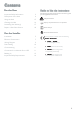
Contents For the User Guide to Use the instructions Important Safety Information 2 Description of the Hob 4 Using the Hob 15 Cleaning the Hob 16 Something Not Working? 17 Repairs - After Sales Service 18 The following symbols will be found in the text to guide you throughout the Instructions: Safety Instructions " Step by step instructions for an operation Hints and Tips Enviromental information For the Installer Installation 5 Electrical Connections 7 Wiring Diagram 9 Fault Finding
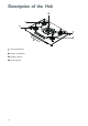
Description of the Hob 2 1 1 1 4 1 . Semi-rapid Burners 2 . Triple crown Burner 3 . Auxiliary Burner 4 .
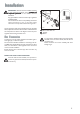
Installation IMPORTANT IMPORTANT:: This hob must be installed according to the instruction supplied, and by qualified and competent personnel to the relevant National Standards. Any gas installation must be carried out by a registered CORGI installer. The manufacturer will not accept liability, should the above instructions or any of the other safety instructions incorporated in this book be ignored.
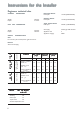
Instructions for the Installer Engineers technical data OVERALL DIMENSIONS Width: Depth: CUT 680 mm. 510 mm. OUT DIMENSIONS Width: Depth: 560 mm. 480 mm. Semi-rapid Burner Heat Input 1.9 kW (6,483 BTU/HR) Auxiliary Burner Heat Input 1.0 kW (3,412 BTU/HR) Triple Cr o wn Burner Cro Heat Input 3.
Electrical Connections THIS HOB MUST BE EAR THED EARTHED THED.. Any electrical work required to install this hob should be carried out by a qualified electrician or competent person, in accordance with the current regulations. Electrical Requirements Any permanent electrical installation must comply with the latest I.E.E. Regulations and local Electricity Board regulations. For your own safety this should be undertaken by a qualified electrician, e.g.
Permanent Connection In the case of a permanent connection, it is necessary that you install a double pole switch between the hob and the electricity supply (mains), with a minimum gap of 3 mm between the switch contacts and of a type suitable for the required load in compliance with the current electric regulations. The switch must not break the yellow and green earth cable at any point. Ensure that the hob supply cable does not come into contact with surfaces with temperatures higher than 50 deg. C.
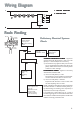
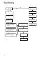
Wiring Diagram L 1. IGNITOR SWITCHES L 2. IGNITOR UNIT 1 2 1 3 4 N 5 6 2 N Fault Finding Brown Blue Green Yellow Pr eliminar Preliminar eliminaryy Electrical Systems Check START Isolate appliance and carry out: A: Earth Continuity check. Blue Brown Green Yellow NO YES Carry out: B: Insulation check. Has inlet fuse blown? NO YES Inlet wiring faulty. Rectify any fault. Isolate appliance and carry out: B: Insulation check. Rectify any fault including replacing fuses as necessary.
Fault Finding Does ignitor spark? YES Check gas supply at burner NO Check plug top fuse and replace if necessary Light burner manually Check polarity and earth continuity of supply point Check by pass simmer adjusted Check position of the electrode Check earth continuity of appliance Check continuity from 'N' on the mains connector block and "N" on the ignitor unit Check continuity from 'L' on the mains connector block and the taps ignition switches Check continuity from ignition switches connect
Commissioning When the hob has been fully installed it will be necessary to check the minimum flame setting.To do this, follow the procedure below. ! Turn the gas tap to the MAX position and ignite. ! Set the gas tap to the MIN flame position then turn the control knob from MIN to MAX several times. If the flame is unstable or is extinguished follow the procedure below. Procedure: Re-ignite the burner and set to MIN. Remove the control knob.
Building In IMPORTANT: This hob must be installed according to the instruction supplied, and by qualified and competent personnel to the relevant National Standards. B uilding over a cupboard or dra w er draw If the hob is to be installed above a cupboard or drawer it will be necessary to fit a heat resistant board below the base of the hob on the underside of the work surface. It is also recommended to carry out the electrical connection to the hob as shown in diagrams 1 and 2.
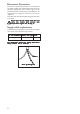
Cut Out Size The dimensions of the cut-out are given in the diagram. Rectangular cut-out size for hob Dimensions are given in mm.
Impor tant Saf ety Requir ements Important Safety Requirements ‘This hob must be installed in accordance with the Gas Safety (Installation and Use) Regulations (Current Edition) and the IEE Wiring Regulations (Current Edition). FITTING THE GAS HOB WITHOUT A COOKER HOOD ABOVE 600 mm Pr ovision ffor or vventilation entilation Pro Detailed recommendations are contained in the following National Standards Codes Of Practice: B.S. 6172/ B.S. 5440, Part 2 and B.S. 6891 Current Editions.
Using the Hob Hob burners " ! ! ! To light a burner: push in the relevant control and turn it to maximum position; then adjust the flame as required. If the burner does not ignite, turn the control knob to zero, and try again. If you use a saucepan which is smaller than the recommended size, the flame will spread beyond the bottom of the vessel, causing the handle to overheat. Take care when frying food in hot oil or fat, as the overheated splashes could easily ignite.
Cleaning the Hob Before any maintenance or cleaning can be carried out, you must DISCONNECT the hob from the electricity supply. If scratches or cracks are noticed, disconnect the hob from the electrical supply and call you nearest Service Force Centre. Keep all objects and materials which can melt away from the cooking surface, e.g. plastics, aluminium foil. The hob is best cleaned whilst it is still warm, as spillage can be removed more easily than if it is left to cool.
Something Not Working? If the hob is not working correctly, please carry out the following checks before contacting your local Service Force repair agent. IMPORTANT: if you call out an engineer to fault listed below, or to repair a fault caused by incorrect use or installation, a charge will be made even if the appliance is under guarantee.
Repairs - After Sales Ser vice Service If your hob is not performing satisfactorily; consult the fault finding guide within this instruction book (Something not working on the previous page). In the event of a fault occurring which you cannot resolve yourself from advice given within this instruction manual. Your first step is to contact our extended warranty administrators on 0870 0107887 who will give you details of your local Service Force repair agent.
35692-8501 07/06 Grafiche MDM - Forlì John Lewis Partnership 171 Victoria Street London SW1E 5NN www. johnlewis.