
Install Instructions


MNEZ123 111820
– 11 –
Model EZ 1,2,3 and LF Oil/Bio-fuel Burners — Instruction Manual
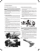
Removing/installing head assembly
Use care when handling burner components after
the burner has been ring. Components can be
hot and could cause severe personal injury.
You will need to remove the combustion head assembly for
inspection of the assembly, replacement of the oil nozzle or
adjustment of electrodes.
Note: Do not have to remove access cover unless combus-
tion head has bafe.
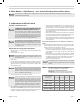
To remove the assembly:
1. Loosen, and then rotate the two ignitor hold-down clamps
securing the ignitor in place. Swing the ignitor plate open.
2. Disconnect the nozzle line heater harness (if applicable).
3. Unscrew the oil line tting and thumb nut at the burner
housing.
4. Pull the threaded end of the oil tube into the blower hous-
ing (Figure 5).
5. Rotate the assembly 180° so the electrodes are upside
down. This places the electrode insulators out of the way
for easy removal.
6. Remove the combustion head assembly, as shown in Fig-
ure 5, by pulling the assembly up and out of the housing.
7. Handle the assembly with care to avoid bending/mov-
ing the electrodes, or damaging the electrode ceramic
insulators.
8. Inspect the gasket on the bottom of the ignitor plate. The
gasket prevents air from escaping from the housing.
Replace the gasket if not in good condition.
9. Inspect the ignitor contact clips. Clean or replace if nec-
essary to ensure reliable contact with the electrodes.
Figure 5 Inserting/removing combustion head assembly
3. Prepare Burner
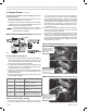
Install nozzle/check electrodes
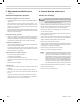
1. Loosen the clamp screw on the retention ring assembly
(see Figure 6). Slide the retention ring assembly off of
the nozzle adapter.
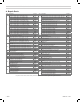
2. Install and tighten the nozzle shown in Table 1, page 4,
for retrot applications. Install the nozzle given in the
appliance manual when application information for the
EZ 1,2,3 oil burner is given.
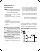
3. For OEM applications with a nozzle, verify nozzle is cor-
rect for the appliance and verify it is tight.
4. Hold the nozzle adapter securely when removing or re-
placing the nozzle (Figure 7). Take care not to damage
the electrode insulators or to bend the electrodes in the
process.
Figure 6 Electrode placement, retention ring assembly and
nozzle adapter
Inspect the nozzle adapter before replacing
the nozzle. If the threads have been damaged
or shows score marks, replace the nozzle line/
adapter assembly.
5. Replace the retention ring assembly by slipping one of
the riveted arms through the gap between the electrode
tips. Align this arm straight up, with the ring clamp rmly
against the nozzle adapter shoulder. Then tighten the
clamping screw.
6. Check the electrode settings. Position the electrodes as
shown in Figure 6. These settings are critical in ensuring
a reliable ignition. Once the electrodes are set, check all
clamps to be sure they are securely tightened.
Figure 7 Carefully support the nozzle adapter when removing
or installing nozzle