Instruction Manual RESIDENTIAL GAS WATER HEATERS POWER VENTED GAS MODELS W/HOT SURFACE IGNITION NOT FOR USE IN MANUFACTURED (MOBILE) HOMES CANADIAN MANUAL • For Your Safety • AN ODORANT IS ADDED TO THE GAS USED BY THIS WATER HEATER. ALL TECHNICAL AND WARRANTY QUESTIONS: SHOULD BE DIRECTED TO THE LOCAL DEALER FROM WHOM THE WATER HEATER WAS PURCHASED. IF YOU ARE UNSUCCESSFUL, PLEASE WRITE TO THE COMPANY LISTED ON THE RATING PLATE ON THE WATER HEATER.
SAFE INSTALLATION, USE AND SERVICE Your safety and the safety of others is extremely important in the installation, use and servicing of this water heater. Many safety-related messages and instructions have been provided in this manual and on your own water heater to warn you and others of a potential injury hazard. Read and obey all safety messages and instructions throughout this manual.
GENERAL SAFETY 3
GENERAL SAFETY 4
TABLE OF CONTENTS Vent Attenuation Assembly Installation Instructions........ 21-22 Vent Pipe Preparation................................................ 23-24 LIGHTING & OPERATING LABEL..........................................25 TEMPERATURE REGULATION.............................................26 FOR YOUR INFORMATION....................................................27 Start Up Conditions Smoke/Odor.............................................................27 Thermal Expansion.........................
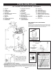
TYPICAL INSTALLATION GET TO KNOW YOUR WATER HEATER - GAS MODELS A Vent Pipe B Anode C Hot Water Outlet D Outlet (120 VAC) F Gas Supply G Main Manual Gas Shut Off Valve H Ground Joint Union J Dirt Leg K Outer Door L Union M Inlet Water Shut Off Valve N Cold Water Inlet O Inlet Dip Tube P Temperature & Pressure Relief Valve Q Rating Plate R Insulation S Vent Terminal T Drain Valve U Igniter And Main Burner W Metal Drain Pan X Gas Control Valve/Thermostat Y Control Harness* AA Motor &
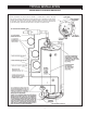
TYPICAL INSTALLATION CONDENSATE HOSE AND DRAIN PAN * Note: Condensate Trap Loops must be oriented in a vertical plane as shown. The traps also must be primed by filling half of the loop with water prior to operating the water heater. Carefully plan the location of the loops and straight sections of hose prior to cutting hoses. If necessary, secure the hoses to the side of the water heater or some other rigid structure to prevent crimping. While securing the hoses, do not pierce or crimp the hoses.
TYPICAL INSTALLATION MIXING VALVE USAGE FIGURE 3. HOTTER WATER CAN SCALD: This appliance has been design certified as complying with American National Standard/CSA Standard for water heaters and is considered suitable for: Water heaters are intended to produce hot water. Water heated to a temperature which will satisfy space heating, clothes washing, dish washing, and other sanitizing needs can scald and permanently injure you upon contact.
LOCATING THE NEW WATER HEATER Facts to Consider About the Location Carefully choose an indoor location for the new water heater, because the placement is a very important consideration for the safety of the occupants in the building and for the most economical use of the appliance. This water heater is not for use in manufactured (mobile) homes or outdoor installation. Whether replacing an old water heater or putting the water heater in a new location, the following critical points must be observed: 1.
in an alcove or closet, the entire floor must be covered by the panel. Failure to heed this warning may result in a fire hazard. If this water heater will be used in beauty shops, barber shops, cleaning establishments, or self-service laundries with dry cleaning equipment, it is imperative that the water heater or water heaters be installed so that combustion and ventilation air be taken from outside these areas.
one square inch per 1000 Btu/hr (22 cm2/kW) of the total input of all appliances in the enclosure, but not less than 100 square inches (645 cm2). If the confined space is within a building of tight construction, air for combustion and ventilation must be obtained from outdoors. When directly communicating with the outdoors or communicating through vertical ducts, two permanent openings, located in the above manner, should be provided.
INSTALLING THE NEW WATER HEATER CHEMICAL VAPOR CORROSION CORROSION OF THE FLUEWAYS AND VENT SYSTEM MAY OCCUR IF AIR FOR COMBUSTION CONTAINS CERTAIN CHEMICAL VAPORS. SUCH CORROSION MAY RESULT IN FAILURE AND RISK OF ASPHYXIATION. Spray can propellants, cleaning solvents, refrigerator and air conditioning refrigerants, swimming pool chemicals, calcium and sodium chloride (water softener salt), waxes, and process chemicals are typical compounds which are potentially corrosive.
Figure 10 shows typical attachment of water piping to the water heater. The water heater is equipped with 3/4 inch NPT water connections. (150 psi = 1,035 kPa) and a discharge capacity not less than the water heater input rate as shown on the model rating plate. NOTE: If using copper tubing, solder tubing to an adapter before attaching the adapter to the water heater connections. Do not solder the water lines directly to the water heater connections. It will harm the dip tube and damage the tank.
This heater is approved for operation up to 5,300 feet (1,615 m) without alteration. High altitude models are available from the factory for elevations between 5,300 feet (1,615 m) and 10,100 feet (3,079 m). Gas Piping Make sure the gas supplied is the same type listed on the model rating plate. The inlet gas pressure must not exceed 14 inch water column (3.5 kPa) for natural and propane gas (L.P.). The minimum inlet gas pressure shown on the rating plate is that which will permit firing at rated input.
SEDIMENT TRAPS Never use this water heater unless it is completely full of water. To prevent damage to the tank, the tank must be filled with water. Water must flow from the hot water faucet before turning “ON” gas to the water heater. To fill the water heater with water: 1. Close the water heater drain valve by turning the handle to the right (clockwise). The drain valve is on the lower front of the water heater. 2. Open the cold water supply valve to the water heater.
CANADIAN HORIZONTAL VENT CLEARANCES FIGURE 15 VENT PIPE TERMINATION Instructions on proper installation through a sidewall are provided in Figure 15. The first step is to determine where the vent pipe will terminate. See Figures 15, 20 and 21. The vent may terminate through a sidewall as shown in Figure 20 or through the roof as shown in Figure 21. Plan the vent system layout so that proper clearances are maintained from plumbing and wiring.
PLANNING THE VENT SYSTEM exceed the lengths discussed above, where each elbow is equal to 5 feet (1.5 m) of straight pipe. If the water heater is being installed as a replacement for an existing power vented heater in pre-existing venting, a thorough inspection of the existing venting system must be performed prior to any installation work.
The condensate trap may be primed by filling the CONDENSATE U-ASSEMBLY with tap water using the supplied hose while the water heater is not operating. The system is fully primed when the hose is lowered below the hose clamp on the side of the water heater and water begins to flow out of the hose. In most installations the water heater will self-prime the condensate trap during the first full heat-up cycle.
2. If the Vent Terminal is being installed on the outside of a finished wall, it may be easier to mark both the inside and outside wall. Align holes by drilling a hole through center of the template from the inside through to the outside. The template can now be positioned on the outside wall using drilled hole as a centering point for the template. the wall plate over the pipe to stop against the vent terminal. Place a bead of caulking (not supplied) around the gap between the pipe and cover plate.
INSTALLATION OF VENT SYSTEM, SIDEWALL where it exits the roof. The total vent system should not exceed the equivalent feet of the pipe as listed in Table 1. Provide support for all pipe protruding through the roof. All piping should be properly secured. The vent system piping should be supported every 5 feet (1.5 m) of vertical run and every 3 feet (91 cm) of horizontal run. All piping and fittings must be joined by the proper procedures as described under: VENT PIPE PREPARATION.
VENT ATTENUATION ASSEMBLY INSTALLATION INSTRUCTIONS supplied with kit) that may be found at a local hardware store. Failure to properly support the VAA and the surrounding vent pipe could create a hazardous situation. DO NOT puncture any surface of the VAA. The Vent Attenuation Assembly (VAA) is designed to provide a reduction in fan noise created in the blower wheel. This installation of this VAA is optional. Review directions thoroughly prior to installing the new VAA.
8. Take the end of the tube at the bottom of the floor and route it to a suitable drain. This will provide an area where the condensate can drain without affecting the area around the appliance. 9. Once installed along with the rest of the vent configuration, make sure to operate the unit through at least one heat up cycle to ensure there is no leakage around the hose barb or any joints of the VAA or vent pipe system.
VENT PIPE PREPARATION PRIMER It is recommended that Tetrahydrofuran (THF) be used to prepare the surfaces of pipe and fittings for solvent welding. Do not use water, rags, gasoline or any other substitutes for cleaning PVC or CPVC surfaces. A chemical cleaner such as MEK may be used. 1. INITIAL PREPARATION A. Make sure the solvent cement you are planning to use is designed for the specific application you are attempting. B.
B. Deburring Use a knife, plastic pipe deburring tool, or file to remove burrs from the end of small diameter pipe. Be sure to remove all burrs from around the inside as well as the outside of the pipe. A slight chamfer (bevel) of about 10°-15° should be added to the end to permit easier insertion of the pipe into the end of the fitting. Failure to chamfer the edge of the pipe may remove cement from the fitting socket, causing the joint to leak. STEP E F.
FOR YOUR SAFETY READ BEFORE OPERATING WARNING: If you do not follow these instructions exactly, a fire or explosion may result causing property damage, personal injury or loss of life. BEFORE OPERATING: ENTIRE SYSTEM MUST BE FILLED WITH WATER AND AIR PURGED FROM ALL LINES. A. This appliance does not have a pilot. It is equipped with • an ignition device which automatically lights the burner. Do NOT try to light the burner by hand. C. B. BEFORE OPERATING smell all around the appliance area for gas.
TEMPERATURE REGULATION It is recommended that lower water temperatures be used to avoid the risk of scalding. It is further recommended, in all cases, that the water temperature be set for the lowest temperature which satisfies your hot water needs. This will also provide the most energy efficient operation of the water heater. To avoid any unintentional changes in water temperature settings, the control has a tamper resistant feature for changing the temperature setting.
FOR YOUR INFORMATION START UP CONDITIONS a. A concentration of sulfate in the supply water. b. Little or no dissolved oxygen in the water. c. A sulfate reducing bacteria which has accumulated within the water heater (this harmless bacteria is nontoxic to humans). d. An excess of active hydrogen in the tank. This is caused by the corrosion protective action of the anode. SMOKE/ODOR It is not uncommon to experience a small amount of smoke and odor during the initial start-up.
PERIODIC MAINTENANCE Venting System Inspection characteristics and ignition sequences. This can be done by removing the Outer Door and viewing the main burner operation through the Viewport on the Inner Door, see Figure 1. The main burner should provide complete combustion of gas, ignite rapidly, give reasonably quiet operation, and cause no excessive flame lifting from the burner ports.
Temperature-Pressure Relief Valve Operation INSTALLED IN SUITABLE AREA: To insure sufficient ventilation and combustion air supply, proper clearances from the water heater must be maintained. See “Locating the New Water Heater” section. Combustible materials such as clothing, cleaning materials, or flammable liquids, etc. must not be placed against or adjacent to the water heater which can cause a fire.
Service the water heater contact a service agency. If you are not thoroughly familiar with gas codes, your water heater, and safety practices, contact your gas supplier or qualified installer to check the water heater. Use this guide to check a “Leaking” water heater. Many suspected “Leakers” are not leaking tanks. Often the source of the water can be found and corrected. Read this manual first.
REPAIR PARTS LIST 5 Key No.
TROUBLESHOOTING GUIDELINES TROUBLE SHOOTING Please check guidelines below. For your safety, water heater service should be performed only by a qualified service technician. Read the GENERAL SAFETY INFORMATION section first. INTELLI-VENT TROUBLESHOOTING CHART - RESIDENTIAL CONTROL # LED STATUS 1 A B C PROBLEM Inadequate or no earth ground sensed by the Intelli-Vent™ control. SOLUTION 1. Ensure the wall outlet is properly grounded. 2.
TROUBLESHOOTING GUIDELINES TROUBLE SHOOTING Please check guidelines below. For your safety, water heater service should be performed only by a qualified service technician. Read the GENERAL SAFETY INFORMATION section first. INTELLI-VENT TROUBLESHOOTING CHART - RESIDENTIAL CONTROL # LED STATUS 6 A B C PROBLEM Ignition/flame failure. The water heater has reached the maximum number of retries and is currently locked out for one hour. SOLUTION 1.
TROUBLESHOOTING GUIDELINES These guidelines should be utilized by a qualified service agent.
LIMITED RESIDENTIAL GAS WARRANTY b. Shipping and delivery charges for forwarding the new water heater or replacement part from the nearest distributor and returning the claimed defective heater or part to such distributor except in the state of California where such charges are the manufacturer’s responsibility. c. All cost necessary or incidental for handling and administrative charges, and for any materials and/or permits required for installation of the replacement heater or part.
GSW Water Heating 599 Hill Street West Fergus, ON Canada N1M 2X1 Should you have any questions please Email us at techsupport@gsw-wh.com or Visit our websites: www.gsw-wh.com or www.johnwoodwaterheaters.com or Call our Technical Support line at 1-888-GSW-TECH (479-8324) GSW Water Heating is a division of A.O.Smith Enterprises Ltd.