
Inc. Air Conditioner User Manual


Table Of Contents
- 1H-Heading1 - GENERAL
- 1H-Heading1 - INSPECTION
- 1H-Heading1 - RENEWAL PARTS
- 1H-Heading1 - APPROVALS
- Figure Title - Figure 1 - PRODUCT NOMENCLATURE
- 1H-Heading1 - INSTALLATION
- 2H-Heading2 - LIMITATIONS
- TableTitle - TABLE 1: UNIT APPLICATION DATA
- 2H-Heading2 - LOCATION
- 2H-Heading2 - RIGGING OR HANDLING
- TableTitle - TABLE 2: UNIT WEIGHTS AND CENTER OF GRAVITY
- Figure Title1 - FIGURE 2 - UNIT CENTER OF GRAVITY
- 2H-Heading2 - CLEARANCES
- 2H-Heading2 - DUCT WORK
- 2H-Heading2 - ROOF CURB
- 2H-Heading2 - FILTERS
- 2H-Heading2 - CONDENSATE DRAIN
- 2H-Heading2 - SERVICE ACCESS
- 2H-Heading2 - THERMOSTAT
- 2H-Heading2 - POWER AND CONTROL WIRING
- Figure Title1 - FIGURE 3 - typical FIELD control WIRING DIAGRAM
- Figure Title1 - FIGURE 4 - typical field POWER WIRING DIAGRAM
- 2H-Heading2 - COMPRESSORS
- TableTitle - TABLE 3: NATURAL GAS APPLICATION DATA
- TableTitle - TABLE 4: PROPANE (LP) GAS APPLICATION DATA
- 2H-Heading2 - GAS PIPING
- 2H-Heading2 - GAS CONNECTION
- Figure Title1 - FIGURE 5 - EXTERNAL SUPPLY CONNECTION EXTERNAL SHUT-OFF
- TableTitle - TABLE 5: NATURAL GAS PIPE SIZING CHART
- TableTitle - TABLE 6: PROPANE (LP) GAS PIPE SIZING CHART
- 2H-Heading2 - FLUE VENT HOOD
- Figure Title1 - FIGURE 6 - FLUE VENT OUTLET AIR HOOD
- TableTitle - Table 7: PHYSICAL DATA
- TableTitle - Table 8: ELECTRICAL DATA
- Figure Title1 - FIGURE 7 - UNIT DIMENSIONS - FRONT
- TableTitle - TABLE 9: UNIT DIMENSIONS FRONT
- TableTitle - TABLE 10: UNIT MINIMUM CLEARANCES
- Figure Title1 - FIGURE 8 - UNIT DIMENSIONS - FRONT & BOTTOM
- Figure Title1 - FIGURE 9 - UNIT DIMENSIONS - BACK & BOTTOM
- 1H-Heading1 - SEQUENCE OF OPERATION
- 2H-Heading2 - HEATING
- TableTitle - TABLE 11: IGNITION CONTROL BOARD FLASH CODES
- 2H-Heading2 - COOLING
- 2H-Heading2 - CIRCULATING FAN
- 1H-Heading1 - START-UP
- 2H-Heading2 - PRE-START CHECK LIST
- 2H-Heading2 - OPERATING INSTRUCTIONS
- 2H-Heading2 - TO TURN OFF GAS TO UNIT
- 2H-Heading2 - POST-START CHECK LIST (GAS)
- 2H-Heading2 - MANIFOLD GAS PRESSURE ADJUSTMENT
- Figure Title1 - FIGURE 10 - GAS VALVE - FRONT
- Figure Title1 - FIGURE 11 - GAS VALVE - REAR
- 2H-Heading2 - BURNER INSTRUCTIONS
- 2H-Heading2 - PILOT INSTRUCTIONS
- Figure Title1 - FIGURE 12 - PROPER FLAME ADJUSTMENT
- 2H-Heading2 - ADJUSTMENT OF TEMPERATURE RISE
- 2H-Heading2 - CHECKING GAS INPUT
- TableTitle - TABLE 12: GASE RATE - CUBIC FEET PER HOUR
- 2H-Heading2 - Checking Supply Air CFM
- Figure Title1 - FIGURE 13 - DYA Coil Delta P vs. Airflow
- TableTitle - TABLE 13: SUPERHEAT CHARGING TABLE FOR DYA036
- TableTitle - TABLE 14: SUPERHEAT CHARGING TABLE FOR DYA042
- TableTitle - TABLE 15: SUPERHEAT CHARGING TABLE FOR DYA048
- TableTitle - TABLE 16: SUPERHEAT CHARGING TABLE FOR DYA060
- Figure Title - FIGURE 14 - TYPICAL WIRING DIAGRAM DYA 036, 042, 048, 060 (208/230-3-60 POWER SUPPLY)
- Figure Title - FIGURE 15 - TYPICAL WIRING DIAGRAM DYA 036, 042, 048, 060 (460-3-60 POWER SUPPLY)
- Figure Title - Figure 16: WIRING DIAGRAM DETAIL A (460-3-60 POWER SUPPLY)
- 1H-Heading1 - TYPICAL WIRING DIAGRAM NOTES
- Figure Title - FIGURE 17 - TYPICAL WIRING DIAGRAM LEGEND
- 1H-Heading1 - TABLE OF CONTENTS
- 1H-Heading1 - LIST OF FIGURES
- 1H-Heading1 - LIST OF TABLES
341426-BIM-A-0108
18 Johnson Controls Unitary Products
CHECKING SUPPLY AIR CFM
To check the supply air CFM after the initial balancing
has been completed:
1. Remove the two ¼ inch dot plugs in the duct panel.
2. Insert at least 8 inches of ¼ inch tubing into each of
these holes for sufficient penetration into the airflow on
both sides of the indoor coil.
3. Using an inclined manometer, determine the pressure
drop across the dry evaporator coil. Since the moisture
on an evaporator coil may vary greatly, measuring the
pressure drop across a wet coil under field conditions
would be inaccurate. To ensure a dry coil, the compres-
sors should be deactivated while the test is being run.
4. Knowing the pressure drop across a dry coil, the actual
CFM through the unit can be determined from the curve
in Coil Delta P vs. Supply Air CFM figure.
After readings have been obtained, remove the tubes and
reinstall the two ¼ inch plugs removed in Step 1.
De-energize the compressors before taking any test mea-
surements to ensure a dry indoor coil.
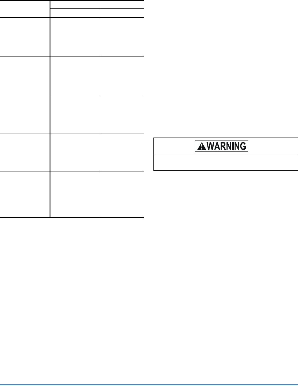
TABLE 12: GASE RATE - CUBIC FEET PER HOUR
1
1.
EXAMPLE: By actual measurement, it takes 38 seconds for the
hand on the 1-cubic foot dial to make a revolution with just a
100,000 BTUH furnace running. Using this information, locate
38 seconds in the first column of Table 12. Read across to the
column headed “1 Cubic Foot,” where you will see that 95 cubic
feet of gas per hour are consumed by the furnace at that rate.
Multiply 95 x 1050 (the BTU rating of the gas obtained from the
local gas company). The result is 99,750 BTUH, which is close
to the 100,000 BTUH rating of the furnace.
SECONDS
FOR ONE
REV.
SIZE OF TEST DIAL
1/2 CU. FT. 1 CU. FT.
10 180 360
12 150 300
14 129 257
16 113 225
18 100 200
20 90 180
22 82 164
24 75 150
26 69 138
28 64 129
30 60 120
32 56 113
34 53 106
36 50 100
38 47 95
40 45 90
42 43 86
44 41 82
46 39 78
48 37 75
50 36 72
52 35 69
54 34 67
56 32 64
58 31 62
60 30 60
Failure to properly adjust the total system air quan-
tity can result in extensive system damage.