
Inc. Air Conditioner User Manual


Table Of Contents
- 1H-Heading1 - GENERAL
- 1H-Heading1 - INSPECTION
- 1H-Heading1 - RENEWAL PARTS
- 1H-Heading1 - APPROVALS
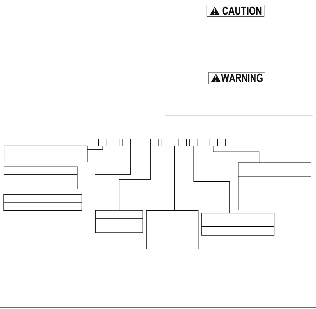
- Figure Title - Figure 1 - PRODUCT NOMENCLATURE
- 1H-Heading1 - INSTALLATION
- 2H-Heading2 - LIMITATIONS
- TableTitle - TABLE 1: UNIT APPLICATION DATA
- 2H-Heading2 - LOCATION
- 2H-Heading2 - RIGGING OR HANDLING
- TableTitle - TABLE 2: UNIT WEIGHTS AND CENTER OF GRAVITY
- Figure Title1 - FIGURE 2 - UNIT CENTER OF GRAVITY
- 2H-Heading2 - CLEARANCES
- 2H-Heading2 - DUCT WORK
- 2H-Heading2 - ROOF CURB
- 2H-Heading2 - FILTERS
- 2H-Heading2 - CONDENSATE DRAIN
- 2H-Heading2 - SERVICE ACCESS
- 2H-Heading2 - THERMOSTAT
- 2H-Heading2 - POWER AND CONTROL WIRING
- Figure Title1 - FIGURE 3 - typical FIELD control WIRING DIAGRAM
- Figure Title1 - FIGURE 4 - typical field POWER WIRING DIAGRAM
- 2H-Heading2 - COMPRESSORS
- TableTitle - TABLE 3: NATURAL GAS APPLICATION DATA
- TableTitle - TABLE 4: PROPANE (LP) GAS APPLICATION DATA
- 2H-Heading2 - GAS PIPING
- 2H-Heading2 - GAS CONNECTION
- Figure Title1 - FIGURE 5 - EXTERNAL SUPPLY CONNECTION EXTERNAL SHUT-OFF
- TableTitle - TABLE 5: NATURAL GAS PIPE SIZING CHART
- TableTitle - TABLE 6: PROPANE (LP) GAS PIPE SIZING CHART
- 2H-Heading2 - FLUE VENT HOOD
- Figure Title1 - FIGURE 6 - FLUE VENT OUTLET AIR HOOD
- TableTitle - Table 7: PHYSICAL DATA
- TableTitle - Table 8: ELECTRICAL DATA
- Figure Title1 - FIGURE 7 - UNIT DIMENSIONS - FRONT
- TableTitle - TABLE 9: UNIT DIMENSIONS FRONT
- TableTitle - TABLE 10: UNIT MINIMUM CLEARANCES
- Figure Title1 - FIGURE 8 - UNIT DIMENSIONS - FRONT & BOTTOM
- Figure Title1 - FIGURE 9 - UNIT DIMENSIONS - BACK & BOTTOM
- 1H-Heading1 - SEQUENCE OF OPERATION
- 2H-Heading2 - HEATING
- TableTitle - TABLE 11: IGNITION CONTROL BOARD FLASH CODES
- 2H-Heading2 - COOLING
- 2H-Heading2 - CIRCULATING FAN
- 1H-Heading1 - START-UP
- 2H-Heading2 - PRE-START CHECK LIST
- 2H-Heading2 - OPERATING INSTRUCTIONS
- 2H-Heading2 - TO TURN OFF GAS TO UNIT
- 2H-Heading2 - POST-START CHECK LIST (GAS)
- 2H-Heading2 - MANIFOLD GAS PRESSURE ADJUSTMENT
- Figure Title1 - FIGURE 10 - GAS VALVE - FRONT
- Figure Title1 - FIGURE 11 - GAS VALVE - REAR
- 2H-Heading2 - BURNER INSTRUCTIONS
- 2H-Heading2 - PILOT INSTRUCTIONS
- Figure Title1 - FIGURE 12 - PROPER FLAME ADJUSTMENT
- 2H-Heading2 - ADJUSTMENT OF TEMPERATURE RISE
- 2H-Heading2 - CHECKING GAS INPUT
- TableTitle - TABLE 12: GASE RATE - CUBIC FEET PER HOUR
- 2H-Heading2 - Checking Supply Air CFM
- Figure Title1 - FIGURE 13 - DYA Coil Delta P vs. Airflow
- TableTitle - TABLE 13: SUPERHEAT CHARGING TABLE FOR DYA036
- TableTitle - TABLE 14: SUPERHEAT CHARGING TABLE FOR DYA042
- TableTitle - TABLE 15: SUPERHEAT CHARGING TABLE FOR DYA048
- TableTitle - TABLE 16: SUPERHEAT CHARGING TABLE FOR DYA060
- Figure Title - FIGURE 14 - TYPICAL WIRING DIAGRAM DYA 036, 042, 048, 060 (208/230-3-60 POWER SUPPLY)
- Figure Title - FIGURE 15 - TYPICAL WIRING DIAGRAM DYA 036, 042, 048, 060 (460-3-60 POWER SUPPLY)
- Figure Title - Figure 16: WIRING DIAGRAM DETAIL A (460-3-60 POWER SUPPLY)
- 1H-Heading1 - TYPICAL WIRING DIAGRAM NOTES
- Figure Title - FIGURE 17 - TYPICAL WIRING DIAGRAM LEGEND
- 1H-Heading1 - TABLE OF CONTENTS
- 1H-Heading1 - LIST OF FIGURES
- 1H-Heading1 - LIST OF TABLES
341426-BIM-A-0108
Johnson Controls Unitary Products 3
GENERAL
Model DYA units are cooling/heating air conditioners
designed for outdoor installation. Only gas piping, electric
power and duct connections are required at the point of
installation.
The gas-fired heaters have spark to pilot ignition. The tubular
heat exchangers are aluminized steel.
This appliance is not to be used for temporary heating of
buildings or structures under construction.
Installer should pay particular attention to the words; NOTE,
CAUTION, and WARNING. NOTES are intended to clarify or
make the installation easier. CAUTIONS are given to prevent
equipment damage. WARNINGS are given to alert the
installer that personal injury and/or equipment damage may
result if installation procedure is not handled properly.
INSPECTION
As soon as a unit is received, it should be inspected for possi-
ble damage during transit. If damage is evident, the extent of
the damage should be noted on the carrier's freight bill. A
separate request for inspection by the carrier's agent should
be made in writing.
RENEWAL PARTS
Contact your local UPG parts distribution center for autho-
rized replacement parts.
APPROVALS
Design certified by CGA and AGA listed as follows:
1. For use as a forced air furnace with cooling unit.
2. For outdoor installation only.
3. For installation directly on combustible flooring or, in
U.S., on wood flooring or Class A; B; C roof covering
material.
4. For installation on combustible material.
5. For use with natural gas and/or propane (LP) gas. Not
suitable for use with conventional venting systems.
This product must be installed in strict compliance
with the enclosed installation instructions and any
applicable local, state, and national codes includ-
ing, but not limited to, building, electrical and
mechanical codes.
Improper installation may create a condition where
the operation of the product could cause personal
injury or property damage.
FIGURE 1 - PRODUCT NOMENCLATURE
D A Y A
PRODUCT CATEGORY
- F
D = Single Package Air Conditioner
PRODUCT IDENTIFIER
YA = 10 SEER Gas Heat/Electric
PRODUCT GENERATION
A = 1st Generation
B = 2nd Generation
N30 6 40 5
042 = 42,000 BTUH
048 = 48,000 BTUH
060 = 60,000 BTUH
036 = 36,000 BTUH
NOMINAL COOLING
CAPACITY (MBH)
T = 208/230-3-60
W = 460-3-60
VOLTAGE CODE
N = Natural Gas Heat Installed
FACTORY
INSTALLED GAS HEAT
045 = 45,000 BTUH
070 = 70,000 BTUH
080 = 80,000 BTUH
090 = 90,000 BTUH
110 = 110,000 BTUH
135 = 135,000 BTUH
NOMINAL GAS HEATING
INPUT CAPACITY