
Inc. Air Conditioner User Manual


Table Of Contents
- 1H-Heading1 - GENERAL
- 1H-Heading1 - INSPECTION
- 1H-Heading1 - RENEWAL PARTS
- 1H-Heading1 - APPROVALS
- Figure Title - Figure 1 - PRODUCT NOMENCLATURE
- 1H-Heading1 - INSTALLATION
- 2H-Heading2 - LIMITATIONS
- TableTitle - TABLE 1: UNIT APPLICATION DATA
- 2H-Heading2 - LOCATION
- 2H-Heading2 - RIGGING OR HANDLING
- TableTitle - TABLE 2: UNIT WEIGHTS AND CENTER OF GRAVITY
- Figure Title1 - FIGURE 2 - UNIT CENTER OF GRAVITY
- 2H-Heading2 - CLEARANCES
- 2H-Heading2 - DUCT WORK
- 2H-Heading2 - ROOF CURB
- 2H-Heading2 - FILTERS
- 2H-Heading2 - CONDENSATE DRAIN
- 2H-Heading2 - SERVICE ACCESS
- 2H-Heading2 - THERMOSTAT
- 2H-Heading2 - POWER AND CONTROL WIRING
- Figure Title1 - FIGURE 3 - typical FIELD control WIRING DIAGRAM
- Figure Title1 - FIGURE 4 - typical field POWER WIRING DIAGRAM
- 2H-Heading2 - COMPRESSORS
- TableTitle - TABLE 3: NATURAL GAS APPLICATION DATA
- TableTitle - TABLE 4: PROPANE (LP) GAS APPLICATION DATA
- 2H-Heading2 - GAS PIPING
- 2H-Heading2 - GAS CONNECTION
- Figure Title1 - FIGURE 5 - EXTERNAL SUPPLY CONNECTION EXTERNAL SHUT-OFF
- TableTitle - TABLE 5: NATURAL GAS PIPE SIZING CHART
- TableTitle - TABLE 6: PROPANE (LP) GAS PIPE SIZING CHART
- 2H-Heading2 - FLUE VENT HOOD
- Figure Title1 - FIGURE 6 - FLUE VENT OUTLET AIR HOOD
- TableTitle - Table 7: PHYSICAL DATA
- TableTitle - Table 8: ELECTRICAL DATA
- Figure Title1 - FIGURE 7 - UNIT DIMENSIONS - FRONT
- TableTitle - TABLE 9: UNIT DIMENSIONS FRONT
- TableTitle - TABLE 10: UNIT MINIMUM CLEARANCES
- Figure Title1 - FIGURE 8 - UNIT DIMENSIONS - FRONT & BOTTOM
- Figure Title1 - FIGURE 9 - UNIT DIMENSIONS - BACK & BOTTOM
- 1H-Heading1 - SEQUENCE OF OPERATION
- 2H-Heading2 - HEATING
- TableTitle - TABLE 11: IGNITION CONTROL BOARD FLASH CODES
- 2H-Heading2 - COOLING
- 2H-Heading2 - CIRCULATING FAN
- 1H-Heading1 - START-UP
- 2H-Heading2 - PRE-START CHECK LIST
- 2H-Heading2 - OPERATING INSTRUCTIONS
- 2H-Heading2 - TO TURN OFF GAS TO UNIT
- 2H-Heading2 - POST-START CHECK LIST (GAS)
- 2H-Heading2 - MANIFOLD GAS PRESSURE ADJUSTMENT
- Figure Title1 - FIGURE 10 - GAS VALVE - FRONT
- Figure Title1 - FIGURE 11 - GAS VALVE - REAR
- 2H-Heading2 - BURNER INSTRUCTIONS
- 2H-Heading2 - PILOT INSTRUCTIONS
- Figure Title1 - FIGURE 12 - PROPER FLAME ADJUSTMENT
- 2H-Heading2 - ADJUSTMENT OF TEMPERATURE RISE
- 2H-Heading2 - CHECKING GAS INPUT
- TableTitle - TABLE 12: GASE RATE - CUBIC FEET PER HOUR
- 2H-Heading2 - Checking Supply Air CFM
- Figure Title1 - FIGURE 13 - DYA Coil Delta P vs. Airflow
- TableTitle - TABLE 13: SUPERHEAT CHARGING TABLE FOR DYA036
- TableTitle - TABLE 14: SUPERHEAT CHARGING TABLE FOR DYA042
- TableTitle - TABLE 15: SUPERHEAT CHARGING TABLE FOR DYA048
- TableTitle - TABLE 16: SUPERHEAT CHARGING TABLE FOR DYA060
- Figure Title - FIGURE 14 - TYPICAL WIRING DIAGRAM DYA 036, 042, 048, 060 (208/230-3-60 POWER SUPPLY)
- Figure Title - FIGURE 15 - TYPICAL WIRING DIAGRAM DYA 036, 042, 048, 060 (460-3-60 POWER SUPPLY)
- Figure Title - Figure 16: WIRING DIAGRAM DETAIL A (460-3-60 POWER SUPPLY)
- 1H-Heading1 - TYPICAL WIRING DIAGRAM NOTES
- Figure Title - FIGURE 17 - TYPICAL WIRING DIAGRAM LEGEND
- 1H-Heading1 - TABLE OF CONTENTS
- 1H-Heading1 - LIST OF FIGURES
- 1H-Heading1 - LIST OF TABLES
341426-BIM-A-0108
Johnson Controls Unitary Products 5
CLEARANCES
All units require certain clearances for proper operation and
service. Refer to Table 10 for the clearances required for
combustion, construction, servicing and proper unit opera-
tion.
DUCT WORK
These units are adaptable to downflow use as well as rear
supply and return air duct openings. To convert to downflow,
use the following steps:
1. Remove the duct covers found in the bottom return and
supply air duct openings. There are four (4) screws
securing each duct cover (save these screws to use
later).
2. Install the duct covers, removed in step one, to the rear
supply and return air duct openings. Secure with the four
(4) screws used in step one.
3. Seal duct covers with silicone caulk.
Duct work should be designed and sized according to the
methods of the Air Conditioning Contractors of America
(ACCA), as set forth in their Manual D.
A closed return duct system shall be used. This shall not pre-
clude use of economizers or ventilation air intake. Flexible
joints may be used in the supply and return duct work to min-
imize the transmission of noise.
NOTE: Be sure to note supply and return openings.
Refer to Figure 9 for information concerning rear and bottom
supply and return air duct openings.
ROOF CURB
On applications when a roof curb is used, the unit must be
positioned on the curb so the front of the unit is tight against
the curb.
FILTERS
A filter rack and a high velocity filters are standard.
Filters must always be used and must be kept clean. When
filters become dirt laden, insufficient air will be delivered by
the blower, decreasing your units efficiency and increasing
operating costs and wear-and-tear on the unit and controls.
Filters should be checked monthly especially since this unit is
used for both heating and cooling.
CONDENSATE DRAIN
A condensate trap is recommended to be installed in the con-
densate drain. The plumbing must conform to local codes.
Use a sealing compound on male pipe threads. Install the
condensate drain line (NPTF) to spill into an open drain.
SERVICE ACCESS
Access to all serviceable components is provided by the fol-
lowing removable panels:
• Blower compartment
• Gas control/electrical service access
Refer to Figure 7 for location of these access panels and min-
imum clearances.
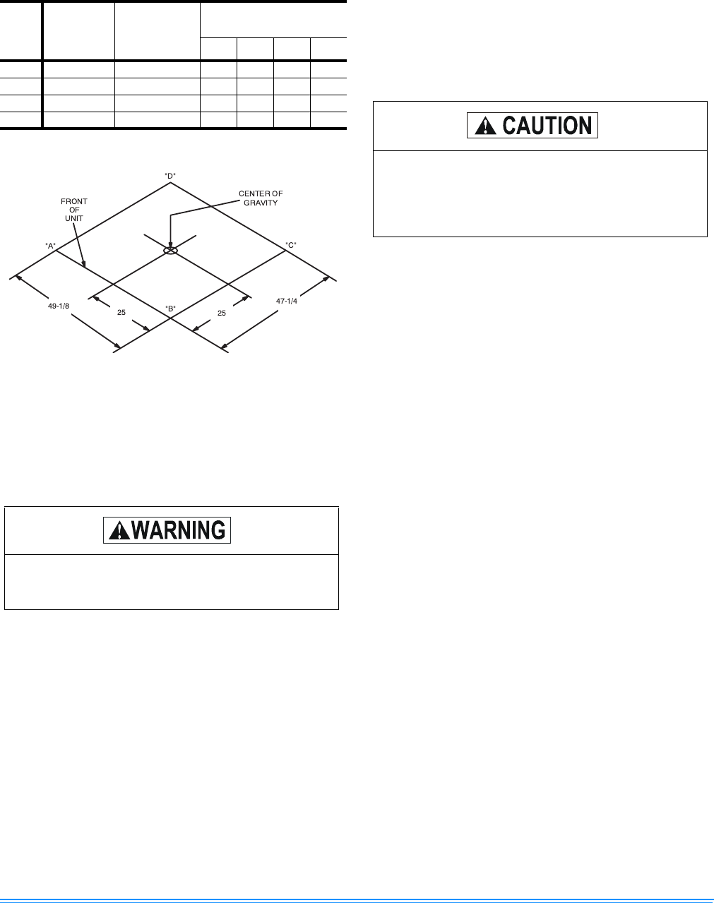
TABLE 2: UNIT WEIGHTS AND CENTER OF
GRAVITY
UNIT
SIZE
SHIPPING
WEIGHT
(LBS.)
OPERATING
WEIGHT
(LBS.)
CORNER WEIGHTS
(LOCATION, LBS.)
“A” “B” “C” “D”
036 400 395 100 96 98 101
042 410 405 104 100 101 105
048 475 470 119 115 116 120
060 480 475 120 116 117 122
FIGURE 2 - UNIT CENTER OF GRAVITY
Do not permit overhanging structures or shrubs to
obstruct the condenser air discharge, combustion
air inlet or vent outlet.
When fastening duct work to the side duct flanges
on the unit, insert the screws through the duct
flanges only. Do not insert the screws through the
casing. Outdoor ductwork must be insulated and
waterproofed.