
Inc. Air Conditioner User Manual


Table Of Contents
- 1H-Heading1 - GENERAL
- 1H-Heading1 - INSPECTION
- 1H-Heading1 - RENEWAL PARTS
- 1H-Heading1 - APPROVALS
- Figure Title - Figure 1 - PRODUCT NOMENCLATURE
- 1H-Heading1 - INSTALLATION
- 2H-Heading2 - LIMITATIONS
- TableTitle - TABLE 1: UNIT APPLICATION DATA
- 2H-Heading2 - LOCATION
- 2H-Heading2 - RIGGING OR HANDLING
- TableTitle - TABLE 2: UNIT WEIGHTS AND CENTER OF GRAVITY
- Figure Title1 - FIGURE 2 - UNIT CENTER OF GRAVITY
- 2H-Heading2 - CLEARANCES
- 2H-Heading2 - DUCT WORK
- 2H-Heading2 - ROOF CURB
- 2H-Heading2 - FILTERS
- 2H-Heading2 - CONDENSATE DRAIN
- 2H-Heading2 - SERVICE ACCESS
- 2H-Heading2 - THERMOSTAT
- 2H-Heading2 - POWER AND CONTROL WIRING
- Figure Title1 - FIGURE 3 - typical FIELD control WIRING DIAGRAM
- Figure Title1 - FIGURE 4 - typical field POWER WIRING DIAGRAM
- 2H-Heading2 - COMPRESSORS
- TableTitle - TABLE 3: NATURAL GAS APPLICATION DATA
- TableTitle - TABLE 4: PROPANE (LP) GAS APPLICATION DATA
- 2H-Heading2 - GAS PIPING
- 2H-Heading2 - GAS CONNECTION
- Figure Title1 - FIGURE 5 - EXTERNAL SUPPLY CONNECTION EXTERNAL SHUT-OFF
- TableTitle - TABLE 5: NATURAL GAS PIPE SIZING CHART
- TableTitle - TABLE 6: PROPANE (LP) GAS PIPE SIZING CHART
- 2H-Heading2 - FLUE VENT HOOD
- Figure Title1 - FIGURE 6 - FLUE VENT OUTLET AIR HOOD
- TableTitle - Table 7: PHYSICAL DATA
- TableTitle - Table 8: ELECTRICAL DATA
- Figure Title1 - FIGURE 7 - UNIT DIMENSIONS - FRONT
- TableTitle - TABLE 9: UNIT DIMENSIONS FRONT
- TableTitle - TABLE 10: UNIT MINIMUM CLEARANCES
- Figure Title1 - FIGURE 8 - UNIT DIMENSIONS - FRONT & BOTTOM
- Figure Title1 - FIGURE 9 - UNIT DIMENSIONS - BACK & BOTTOM
- 1H-Heading1 - SEQUENCE OF OPERATION
- 2H-Heading2 - HEATING
- TableTitle - TABLE 11: IGNITION CONTROL BOARD FLASH CODES
- 2H-Heading2 - COOLING
- 2H-Heading2 - CIRCULATING FAN
- 1H-Heading1 - START-UP
- 2H-Heading2 - PRE-START CHECK LIST
- 2H-Heading2 - OPERATING INSTRUCTIONS
- 2H-Heading2 - TO TURN OFF GAS TO UNIT
- 2H-Heading2 - POST-START CHECK LIST (GAS)
- 2H-Heading2 - MANIFOLD GAS PRESSURE ADJUSTMENT
- Figure Title1 - FIGURE 10 - GAS VALVE - FRONT
- Figure Title1 - FIGURE 11 - GAS VALVE - REAR
- 2H-Heading2 - BURNER INSTRUCTIONS
- 2H-Heading2 - PILOT INSTRUCTIONS
- Figure Title1 - FIGURE 12 - PROPER FLAME ADJUSTMENT
- 2H-Heading2 - ADJUSTMENT OF TEMPERATURE RISE
- 2H-Heading2 - CHECKING GAS INPUT
- TableTitle - TABLE 12: GASE RATE - CUBIC FEET PER HOUR
- 2H-Heading2 - Checking Supply Air CFM
- Figure Title1 - FIGURE 13 - DYA Coil Delta P vs. Airflow
- TableTitle - TABLE 13: SUPERHEAT CHARGING TABLE FOR DYA036
- TableTitle - TABLE 14: SUPERHEAT CHARGING TABLE FOR DYA042
- TableTitle - TABLE 15: SUPERHEAT CHARGING TABLE FOR DYA048
- TableTitle - TABLE 16: SUPERHEAT CHARGING TABLE FOR DYA060
- Figure Title - FIGURE 14 - TYPICAL WIRING DIAGRAM DYA 036, 042, 048, 060 (208/230-3-60 POWER SUPPLY)
- Figure Title - FIGURE 15 - TYPICAL WIRING DIAGRAM DYA 036, 042, 048, 060 (460-3-60 POWER SUPPLY)
- Figure Title - Figure 16: WIRING DIAGRAM DETAIL A (460-3-60 POWER SUPPLY)
- 1H-Heading1 - TYPICAL WIRING DIAGRAM NOTES
- Figure Title - FIGURE 17 - TYPICAL WIRING DIAGRAM LEGEND
- 1H-Heading1 - TABLE OF CONTENTS
- 1H-Heading1 - LIST OF FIGURES
- 1H-Heading1 - LIST OF TABLES
341426-BIM-A-0108
6 Johnson Controls Unitary Products
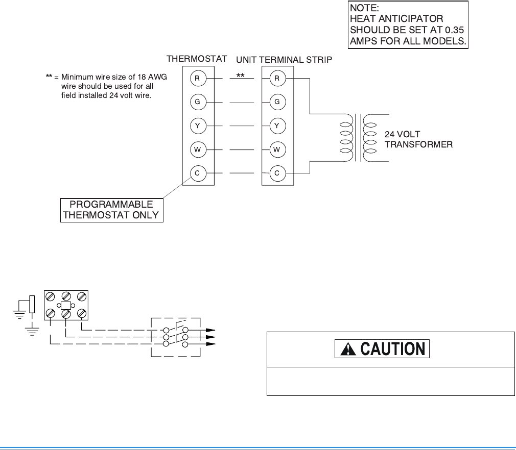
THERMOSTAT
The room thermostat should be located on an inside wall
approximately 56" above the floor where it will not be subject
to drafts, sun exposure or heat from electrical fixtures or
appliances. Follow manufacturer's instructions enclosed with
the thermostat for general installation procedure. Four color
coded insulated wires (minimum #18 AWG) should be used
to connect thermostat to unit. See Figure 3.
POWER AND CONTROL WIRING
Field wiring to the unit must conform to provisions of the cur-
rent N.E.C. ANSI/NFPA No. 70 or C.E.C. and/or local ordi-
nances. The unit must be electrically grounded in accordance
with local codes or, in their absence, with the N.E.C./C.E.C.
Voltage tolerances which must be maintained at the com-
pressor terminals during starting and running conditions are
indicated on the unit Rating Plate and Table 8.
The wiring entering the cabinet must be provided with
mechanical strain relief.
A fused disconnect switch should be field provided for the
unit. If any of the wire supplied with the unit must be replaced,
replacement wire must be of the type shown on the wiring
diagram.
Electrical line must be sized properly to carry the load. Each
unit must be wired with a separate branch circuit fed directly
from the meter panel and properly fused.
Refer to Figure 4 for typical field wiring and to the appropriate
unit wiring diagram for control circuit and power wiring infor-
mation.
COMPRESSORS
Units are shipped with compressor mounting factory-adjusted
for shipping.
FIGURE 3 - TYPICAL FIELD CONTROL WIRING DIAGRAM
FIGURE 4 - TYPICAL FIELD POWER WIRING
DIAGRAM
CONTACTOR
GROUND
LUG
FIELD-SUPPLIED
DISCONNECT
REFER TO ELECTRICAL
DATA TABLES TO SIZE
THE DISCONNECT
THREE
PHASE
POWER
SUPPLY
Loosen compressor mounting bolts a half turn
before operating unit.