
Inc. Air Conditioner User Manual


Table Of Contents
- 1H-Heading1 - GENERAL
- 1H-Heading1 - INSPECTION
- 1H-Heading1 - RENEWAL PARTS
- 1H-Heading1 - APPROVALS
- Figure Title - Figure 1 - PRODUCT NOMENCLATURE
- 1H-Heading1 - INSTALLATION
- 2H-Heading2 - LIMITATIONS
- TableTitle - TABLE 1: UNIT APPLICATION DATA
- 2H-Heading2 - LOCATION
- 2H-Heading2 - RIGGING OR HANDLING
- TableTitle - TABLE 2: UNIT WEIGHTS AND CENTER OF GRAVITY
- Figure Title1 - FIGURE 2 - UNIT CENTER OF GRAVITY
- 2H-Heading2 - CLEARANCES
- 2H-Heading2 - DUCT WORK
- 2H-Heading2 - ROOF CURB
- 2H-Heading2 - FILTERS
- 2H-Heading2 - CONDENSATE DRAIN
- 2H-Heading2 - SERVICE ACCESS
- 2H-Heading2 - THERMOSTAT
- 2H-Heading2 - POWER AND CONTROL WIRING
- Figure Title1 - FIGURE 3 - typical FIELD control WIRING DIAGRAM
- Figure Title1 - FIGURE 4 - typical field POWER WIRING DIAGRAM
- 2H-Heading2 - COMPRESSORS
- TableTitle - TABLE 3: NATURAL GAS APPLICATION DATA
- TableTitle - TABLE 4: PROPANE (LP) GAS APPLICATION DATA
- 2H-Heading2 - GAS PIPING
- 2H-Heading2 - GAS CONNECTION
- Figure Title1 - FIGURE 5 - EXTERNAL SUPPLY CONNECTION EXTERNAL SHUT-OFF
- TableTitle - TABLE 5: NATURAL GAS PIPE SIZING CHART
- TableTitle - TABLE 6: PROPANE (LP) GAS PIPE SIZING CHART
- 2H-Heading2 - FLUE VENT HOOD
- Figure Title1 - FIGURE 6 - FLUE VENT OUTLET AIR HOOD
- TableTitle - Table 7: PHYSICAL DATA
- TableTitle - Table 8: ELECTRICAL DATA
- Figure Title1 - FIGURE 7 - UNIT DIMENSIONS - FRONT
- TableTitle - TABLE 9: UNIT DIMENSIONS FRONT
- TableTitle - TABLE 10: UNIT MINIMUM CLEARANCES
- Figure Title1 - FIGURE 8 - UNIT DIMENSIONS - FRONT & BOTTOM
- Figure Title1 - FIGURE 9 - UNIT DIMENSIONS - BACK & BOTTOM
- 1H-Heading1 - SEQUENCE OF OPERATION
- 2H-Heading2 - HEATING
- TableTitle - TABLE 11: IGNITION CONTROL BOARD FLASH CODES
- 2H-Heading2 - COOLING
- 2H-Heading2 - CIRCULATING FAN
- 1H-Heading1 - START-UP
- 2H-Heading2 - PRE-START CHECK LIST
- 2H-Heading2 - OPERATING INSTRUCTIONS
- 2H-Heading2 - TO TURN OFF GAS TO UNIT
- 2H-Heading2 - POST-START CHECK LIST (GAS)
- 2H-Heading2 - MANIFOLD GAS PRESSURE ADJUSTMENT
- Figure Title1 - FIGURE 10 - GAS VALVE - FRONT
- Figure Title1 - FIGURE 11 - GAS VALVE - REAR
- 2H-Heading2 - BURNER INSTRUCTIONS
- 2H-Heading2 - PILOT INSTRUCTIONS
- Figure Title1 - FIGURE 12 - PROPER FLAME ADJUSTMENT
- 2H-Heading2 - ADJUSTMENT OF TEMPERATURE RISE
- 2H-Heading2 - CHECKING GAS INPUT
- TableTitle - TABLE 12: GASE RATE - CUBIC FEET PER HOUR
- 2H-Heading2 - Checking Supply Air CFM
- Figure Title1 - FIGURE 13 - DYA Coil Delta P vs. Airflow
- TableTitle - TABLE 13: SUPERHEAT CHARGING TABLE FOR DYA036
- TableTitle - TABLE 14: SUPERHEAT CHARGING TABLE FOR DYA042
- TableTitle - TABLE 15: SUPERHEAT CHARGING TABLE FOR DYA048
- TableTitle - TABLE 16: SUPERHEAT CHARGING TABLE FOR DYA060
- Figure Title - FIGURE 14 - TYPICAL WIRING DIAGRAM DYA 036, 042, 048, 060 (208/230-3-60 POWER SUPPLY)
- Figure Title - FIGURE 15 - TYPICAL WIRING DIAGRAM DYA 036, 042, 048, 060 (460-3-60 POWER SUPPLY)
- Figure Title - Figure 16: WIRING DIAGRAM DETAIL A (460-3-60 POWER SUPPLY)
- 1H-Heading1 - TYPICAL WIRING DIAGRAM NOTES
- Figure Title - FIGURE 17 - TYPICAL WIRING DIAGRAM LEGEND
- 1H-Heading1 - TABLE OF CONTENTS
- 1H-Heading1 - LIST OF FIGURES
- 1H-Heading1 - LIST OF TABLES
341426-BIM-A-0108
Johnson Controls Unitary Products 9
i
4. All piping should be cleaned of dirt and scale by ham-
mering on the outside of the pipe and blowing out the
loose dirt and scale. Before initial start-up, be sure that
all of the gas lines external to the unit have been purged
of air.
5. The gas supply should be a separate line and installed in
accordance with all safety codes as prescribed under
Limitations. After the gas connections have been com-
pleted, open the main shut-off valve admitting normal
gas pressure to the mains. Check all joints for leaks with
soap solution or other material suitable for the purpose.
NEVER USE A FLAME.
6. The furnace and its individual manual shut-off valve must
be disconnected from the gas supply piping system dur-
ing any pressure testing of that system at test pressures
in excess of 1/2 psig (3.48 kPa).
The furnace must be isolated from the gas supply piping sys-
tem by closing its individual manual shut-off valve during any
pressure testing of the gas supply piping system at test pres-
sures equal to or less than 1/2 psig (3.48 kPa).
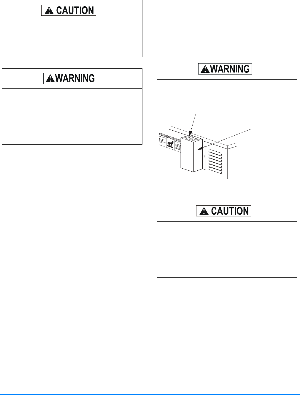
FLUE VENT HOOD
The flue vent hood with screen is not shipped attached. This
hood must be installed to assure proper unit operation. The
hood must be fastened to the outside of the side gas control/
electrical compartment with the screws provided in the bag
attached to the inside of the gas control/electrical compart-
ment, see Figure 6.
If flexible stainless steel tubing is allowed by the
authority having jurisdiction, wrought iron or steel
pipe must be installed at the gas valve and extend
a minimum of two (2) inches outside of the unit
casing.
Natural gas may contain some propane. Propane
being a excellent solvent, will quickly dissolve
white lead or most standard commercial com-
pounds. Therefore, a special pipe dope must be
applied when wrought iron or steel pipe is used.
Shellac base compounds such as gaskoloc or sta-
lastic, and compounds such as rectorseal # 5,
Clyde’s or John Crane may be used.
Flue hood surfaces may be hot.
FIGURE 6 - FLUE VENT OUTLET AIR HOOD
The flue exhaust hood must be properly installed
and within the recommended clearances. Further
communications and action must be given to the
home or building owner(s) to eliminate any unau-
thorized human contact around this area during
the heating cycle. Flue hood surface and immedi-
ate area are designed to operate at high tempera-
tures during the heating cycle.
V E N T O U T L E T S C R E E N
F L U E V E N T O U T L E T
A I R H O O D