
Install Instructions
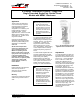
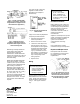

Table Of Contents

Installation Sheets Manual 121
Temperature Controls Section A
Technical Bulletin A19
Issue Date 0588
© 1988 Johnson Controls, Inc. 1
Code No. LIT-121015
Part No. 997-349
A19 Series Temperature Controls -- Single-Pole,
Single-Throw and Single-Pole, Double-Throw
Models with NEMA 1 Enclosure
Application
These controls are designed to
cover a broad range of general
purpose operating temperature
control applications in the
refrigeration, air conditioning and
heating field with a minimum
number of models. Typical
applications are: frozen food cases,
display cases, beverage coolers,
milk coolers, etc. Various control
ranges are available.
Controls are supplied with an
adjustable range (except models
with factory sealed settings) and
adjustable or nonadjustable
differential.
All Series A19 temperature
controls are designed for use
only
as operating controls.
Where an operating control
failure would result in personal
injury and/or loss of property, it
is the responsibility of the
installer to add devices (safety,
limit controls) or systems (alarm,
supervisory systems) that
protect against, or warn of,
control failure.
Installation
Follow equipment manufacturer’s
instructions if provided. If
instructions are not provided
proceed as follows:
Mounting
Controls are normally mounted to a
surface through holes in back of
case.
!
CAUTION: On rough
mounting surfaces use the
top two mounting holes
only. When these controls
are mounted on an uneven
surface using screws in all
four holes, the case can be
twisted enough to affect
the control’s calibration and
operation.
For closed tank applications without
well assembly Part No. FTG13A-
600R packing nut assembly may be
supplied. See Fig. 2 for sequence
of installation. Put parts over
support tube section of element,
placing bulb into tank. Tighten
1/2 in. NPT adapter. Screw packing
nut into adapter with the retaining
washers and packing in place as
shown.
To install models supplied with bulb
well, first install bulb well into tank.
Remove bushing from bulb well and
slide bushing over capillary.
Replace bushing into bulb well.
Push bulb into position in bottom of
well. Tighten set screw in end of
adapter to hold bulb in position.
See Fig. 3 for bulb well illustration.
!
CAUTION: Do not dent or
deform the sensitive bulb of
this control. A dent or
deformation will change the
calibration and cause the
control to cycle at a
temperature lower than the
dial setting. When the bulb
mounting clip is used to
mount the bulb near the
refrigerant tubing, be sure
the sheet metal screw does
not pierce the tubing.
Fig. 1 -- An A19 with external range
adjustment and screwdriver slot.
Adjustments
The A19 temperature controls may
be supplied with an external range
adjustment and screwdriver slot as
shown in Fig. 1, range adjustment
knob or solid cover. Solid cover
models with calibrated dial are
adjusted by removing the cover and
moving dial so the desired setting is
in line with the dial pointer on the
stop bracket. (See Fig. 5.)
Convertible adjustment models can
be field converted from concealed
screwdriver slot adjustment to knob
adjustment or external screwdriver
slot adjustment. They are supplied
with a snap-in plug in the cover to
provide concealed screwdriver slot
adjustment. For knob adjustment
remove the snap-in plug and press
the knob onto the slotted shaft. For
external screwdriver slot adjustment
remove the snap-in plug. The
convertible adjustment models with
remote bulb include a bulb
mounting clip.