
Install Instructions
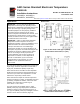
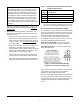
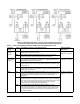
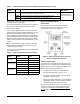
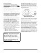
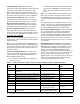
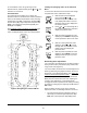
Table Of Contents

A421 Series Standard Electronic Temperature Controls Installation Instructions
2
Parts Included
Each A421 Control includes a Johnson Controls/
PENN® A99 Series temperature sensor. See A99
Series Temperature Sensors, Wiring, and Technical
Specifications for more information about A99 sensors.
A99 Series Temperature Sensors
The A421 controls require an A99 sensor, and each
A421 control includes an A99 sensor. Any A99 Series
sensor works with the A421 Series controls. Do not
replace an A99 Series sensor with any other brand,
series, or type of temperature sensor. See Ordering
Information for available A99 Series sensor models.
The sensor leads may be extended in the field. See
Table 1 for recommended wire sizes and lengths. On
long sensor cable runs, use shielded cable to reduce
Electro-Magnetic Interference (EMI). Observe EMI best
practices when routing sensor leads.
The A99 Series sensors are moisture tolerant and
splash resistant, but do not completely immerse the
A99 sensor in water or any other liquid. Immersing the
sensor can allow liquid to enter the sensor probe where
the stainless steel tube meets the wire cable and result
in sensor failure, which voids any warranty.
In applications where the sensor may be exposed to a
lot of moisture, splashing, or rain, we recommend
mounting the sensor in a vertical position with the cable
at the bottom routed downward to allow moisture to
drain away from the stainless steel probe. Use a
suitable bulb well for complete fluid immersion
applications. See Ordering Information
for a
recommended bulb well.
The A99 Series sensors are positive temperature
coefficient (PTC) sensors. To test an A99 sensor,
disconnect the sensor from the control and measure
the resistance between the sensor leads:
• When the temperature at the sensor is 77°F
(25°C), the resistance should be 1,035 ohms.
• When the temperature at the sensor is 32°F (0°C),
the resistance should be 855 ohms.
See Troubleshooting
for more information.
When an A99 sensor is connected to a standard
A421 control, the range of usable values is restricted
by the control to -40 to 212°F or -40 to 100°C.
See Wiring
, Technical Specifications, and refer to the
A99B Series Temperature Sensors Product/Technical
Bulletin (LIT-125186) for more information regarding
A99 Series sensors.
Mounting
Observe the following guidelines when locating and
mounting an A421 control:
• Ensure that the mounting surface can support the
control, DIN rail, mounting hardware, and any
(user-supplied) panel or enclosure.
• Mount the control in a vertical, upright orientation
wherever possible. DIN rail mounting is strongly
recommended for Type 1 controls.
• In direct-mount applications, mount the control on
a flat and even surface.
Mount the control in a location free of corrosive vapors
and observe the ambient operating conditions listed in
Technical Specifications
for both the A421 control and
the A99 sensor.
• Allow sufficient space for connecting and routing
wires, viewing the LCD, and using the touchpad.
• Do not mount the control on surfaces that are
prone to vibration or in a location where
high-voltage relays, motor starters, other sources
of electromagnetic emissions, or strong radio
frequency may cause interference.
• Do not install the control in an airtight enclosure.
• Do not install heat generating devices with the
control in an enclosure that may cause the ambient
temperature to exceed 150°F (66°C).
To mount a Type 1/IP20 control on DIN rail:
1. Provide a section of 35 mm DIN rail that is longer
than the control width, and mount the DIN rail in a
suitable location using appropriate mounting
hardware.
2. Clip the control module on the rail, position the
module’s upper DIN rail clips on the top rail, and
gently snap the lower clips on to the bottom of the
rail.
To direct-mount a Type 1/IP20 control to a wall or
other flat surface using the four keyhole slots:
1. Remove the enclosure cover, place the control
vertically against the wall surface in a suitable
location, and mark the keyhole slot locations on the
mounting surface.
2. Install appropriate screws or fasteners, leaving the
screw heads approximately one or two turns away
from flush to the mounting surface.