
Install Instructions
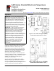
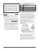
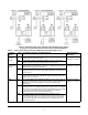
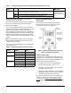
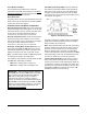
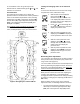
Table Of Contents

A421 Series Standard Electronic Temperature Controls Installation Instructions
4
Observe the wire size restrictions listed in Table 2 on
page 5 and the Electrical Ratings listed in Technical
Specifications.
Observe the following guidelines, procedures, and
illustrations when wiring an A421 Series control and
A99 Series sensor.
• Select only the A99 sensors that are designed to
operate in the ambient operating range that your
A421 control is intended to monitor and control as
shown in Table 7. See Technical Specifications
for
more information.
• Keep the sensor leads as short as possible in your
application. The additional resistance in long
sensor cables creates an offset between the actual
temperature and the displayed temperature. See
Table 1 when extending sensor leads.
• A99 sensors are not polarity specific. Either lead
can be connected to the SEN or COM terminals.
• We recommend 22 AWG, stranded, twisted-pair
cable with a shield for extending sensor cable runs.
TB2 Terminal Block and SPDT Relay Output
The terminals (LC, LNO, and LNC) on the TB2 terminal
block are connected to a SPDT dry-contact relay in the
A421 control (Figure 3). The control does not provide
any internal power to the TB2 terminals or relay
contacts. The A421 control simply energizes and
de-energizes the relay to open and close the contacts
based on the On/OFF temperature values.
Relay De-energized (Off) = LC open to LNO (as
shown in Figure 3) and the relay status LED is off
Relay Energized (On) = LC closed to LNO and the
relay status LED is on
Figure 4 shows how to wire the A421 control to use the
same power source that powers the controlled
equipment to also power the A421 control.
You can also provide an independent power source for
the A421 control on the TB1 terminals and then wire
the TB2 relay terminals to a separate power source for
switching and powering the controlled equipment
circuit.
IMPORTANT: When connecting an A99 sensor
with a shielded cable to an A421 Control, connect
the cable shield drain lead to the COM (common)
terminal on the sensor and binary input terminal
block (TB3). Do not connect the shield at any other
point along the cable, and isolate and insulate the
shield along the entire length of the sensor cable.
Connecting a cable shield at more than one point
can enable transient currents to flow through the
sensor cable shield, which can cause erratic control
operation.
Table 1: Maximum Recommended Sensor Cable
Lengths and Wire Sizes
Wire
Gauge
Maximum Sensor Cable Length
1
,
Feet (Meters)
16 AWG 500 (150)
18 AWG 300 (100)
20 AWG 200 (60)
22 AWG 125 (40)
1. At the listed maximum cable lengths, there is less than
1Fº (0.6Cº) error between the temperature sensed at the
A99 sensor and the temperature displayed on the LCD.
Figure 3: TB2 Terminal Block Showing
Connections to the Internal SPDT Relay