
Install Instructions
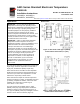
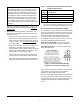
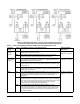
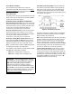
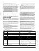
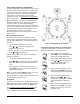
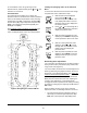
Table Of Contents

A421 Series Standard Electronic Temperature Controls Installation Instructions
7
Three-Button Touchpad
The touchpad has three buttons for setup and
adjustment of the A421 control (Figure 5). See Menu
Navigation Guidelines on page 9 for more information
on using the three-button touchpad.
Relay Status LED
The green LED on the front panel illuminates when the
SPDT output relay is energized and the LC and LNO
contacts are closed. See Figure 5.
Parameter Codes and Modes of Operation
Relay Off Temperature (OFF): Select the temperature
at which the output relay de-energizes, the LC to LNO
relay contacts open (cutout), and the green LED goes
off. The range of usable temperature values is
-40 to 212 °F (-40 to 100 °C) in 1° increments.
Relay On Temperature (On): Select the temperature
at which the output relay energizes, the LC to LNO
relay contacts close (cut in), and the green LED lights.
The range of usable temperature values is
-40 to 212 °F (-40 to 100 °C) in 1° increments.
Heating or Cooling Mode of Operation: When you
select your desired On and OFF values, the control
automatically determines the mode of operation and
displays the proper mode icon on the Main screen.
Note: The A421 Series controls do not have jumpers
for setting up the heating or cooling mode.
The heating or cooling mode is determined by the On
and OFF value relationship as follows:
• OFF > On = Heating mode = Flame icon
• OFF < On = Cooling mode = Snowflake icon
Anti-Short Cycle Delay (ASd): Select the minimum
time that the output relay remains off (de-energized)
before the next on-cycle can start. The ASd interval
overrides any load demand (On) and does not allow
the output relay to go on until the selected ASd interval
has elapsed. See Figure 6.
Anti-short cycle delay is typically used for refrigeration
applications to allow the system pressure to equalize
before restarting the compressor.
Note: When the ASd value is greater than 0, the delay
interval is initiated every time that the A421 control is
powered on and every time that an off-cycle begins.
When the ASd interval is activated, the temperature
sensed at the A99 sensor and the parameter code ASd
flash (alternately) on the LCD. The ASd interval can be
set from 0 to 12 minutes, in 1-minute increments.
Sensor Failure Mode (SF): Select how the control’s
output relay operates (energized or de-energized) in
the event of a sensor or sensor wiring failure. When the
control detects a sensor circuit failure, the output relay
operates in the selected sensor failure mode. The LCD
flashes SF and OP if the sensor circuit is open or SF
and SH if the sensor circuit is shorted.
IMPORTANT: During normal operation, adjusting
just the On value or just the OFF value on the A421
control changes the differential between On and
OFF, and can potentially change the mode of
operation from heating to cooling or cooling to
heating. To maintain a constant differential between
On and OFF, you must adjust both the On and OFF
values by an equal number of degrees; or set up the
control in the Restricted Adjustment Mode. See
Restricting User Adjustment
.
Figure 6: Anti-Short Cycle Delay