
Product Overview
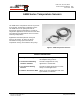
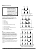
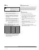
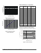
Table Of Contents

D
imensions
1/4 (6)
2 (50)
Figure 5: A99B Sensor, in. (mm)
Accessories
A99B series accessories include the following:
3
(76)
Dia.
3/8
(9.3)
4 3/4
(119)
7/8
(23)
4 1/2
(113.5)
1 11/16
(42)
1 3/8
(35)
EMT
Conduit
Adapter
ADP11A-600R
1/2
(13)
Sun Shield
SHL10A-603R
9 1/8
(229)
1 3/4
(44)
4 5/16
(110)
1
(25.4)
1
(25.4)
Surface Mount Clip
A99-CLP-1
1/4 (6)
PVC Enclosure
BOX10A-600R
Figure 6: Available Accessories, in. (mm)
O
peration
The A99B sensor incorporates a PTC silicon sensing
element whose resistance increases with an increase in
temperature. The sensor has a reference resistance of
1035 ohms at 77°F (25°C). Each element is calibrated
according to a standard graph, as shown in Table 2.
The A99B series sensors are typically used with
Johnson Controls/PENN System 350™ controls, MR
Defrost controls MS Multi-Stage controls, and A419
Electronic Temperature controls.
The A99B sensors can also be used with
Johnson Controls System 27 NOVA; A255 fan speed
control modules; and R78, DX-9100, XP-9102, XPA-4x1,
and XPA-8x1 products.
M
ounting
Mounting Considerations
The A99B sensor may be mounted in virtually any
position. To ensure proper operation of the A99B Series
sensors, observe the following guidelines:
• Mount sensors in areas where they are exposed to
representative temperature conditions and sufficient
air mixing. Avoid mounting the sensors where air
stratification exists.
• Avoid areas subject to excessive mechanical
vibration or electrical noise.
• For outdoor applications, avoid areas where the
sensor will be exposed to direct sunlight because
this causes the sensor to read a higher temperature.
The north side of the building is preferred for outdoor
sensors. If not possible, install a sun shield.
• Use a thermally conductive paste where appropriate
to improve the thermal contact with the sensor.
• Do not subject silicon cable (A99BC) to any silicon-
based fluids, as this will degrade the cable.
A99B Series Temperature Sensors Product/Technical Bulletin 3