
Product Overview
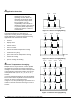
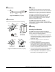
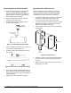
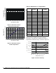
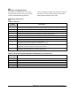
Table Of Contents

W
iring
!
WARNING: Shock Hazard. Disconnect all
power to the controller that the
sensor is connected to before
wiring or servicing.
For wiring, follow the instructions below:
• Make sure all wiring conforms to the National
Electric Code and local regulations.
• Run high and low voltage wiring in separate
conduits. For applications in critical industrial
environments, use a sensor with a shielded
cable (A99BA).
• If wire is added to the sensor leads, additional
resistance may affect the sensor reading.
Longer wires increase resistance, which causes
a shift in the sensor temperature reading.
Note: At the wire lengths listed in Table 1, the
error in the sensed temperature is less
than 1°F (0.5°C).
Table 1: Maximum Sensor Wire Lengths
(for less than 1°F error)
Wire Gauge Wire Length
AWG Feet Meters
14 AWG
800 244
16 AWG)
500 152
18 AWG
310 94
20 AWG
200 61
22 AWG
124 38
• Shielded Cable Models (A99BA) Only: For all
controls, including the Johnson Controls/PENN
System 350, MR, MS, and A419, connect the
sensor cable shield to the controller per the
controller’s instructions.
C
heckout Procedure
Before applying power, make sure installation and wiring
connections are according to job specifications. After
necessary adjustments and electrical connections have
been made, operate the system and observe at least
three complete cycles before leaving the installation.
T
roubleshooting
Check the sensor for proper resistance:
1. Disconnect the sensor from the control.
2. Take a temperature reading at the sensor location.
Be sure to let the thermometer stabilize before
taking a reading.
3. Use the temperature reading from Step 2 to
determine the expected sensor resistance from
Table 2.
4. Using an ohmmeter, measure the actual resistance
across the two sensor leads.
5. Compare the expected resistance to the actual
resistance.
6. If the sensor's actual resistance deviates
substantially from the expected resistance found in
Table 2, replace the sensor.
A99B Series Temperature Sensors Product/Technical Bulletin 5