
User Guide


562156-UIM-A-0610
Johnson Controls Unitary Products 7
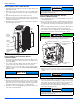
CFM SELECTION BOARD SETTINGS
For proper system operation the CFM Selection Board jumpers must be
set properly.
Refer to the Tech Guide for the recommended air flow settings for each
size condensing unit and matchup.
Set the cooling speed per the instructions for the air handler or furnace
by selecting the correct COOL and ADJ taps. Verify the airflow using
the LED display on the CFM selection board.
The HUMIDISTAT jumper must also be removed if a dehumidistat is
installed.
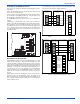
If installed as a communicating system (outdoor, indoor and thermo-
stat), the system will automatically adjust to the optimal airflow settings.
These parameters can also be modified using the Touch Screen Com-
municating Control. Refer to the Touch Screen Communicating Control
owner’s manual for this procedure. Manual setting of the airflow jump-
ers on the ID equipment is not necessary with the Touch Screen Com-
municating Control.
DEHUMIDIFICATION CONTROL
A dehumidification control accessory 2HU06700124 may be used with
variable speed air handlers or furnaces in high humidity areas. This
control works with the variable speed indoor unit to provide cooling at a
reduced air flow, lowering evaporator temperature and increasing latent
capacity. The humidistat in this control opens the humidistat contacts on
humidity rise. To install, refer to instructions packaged with the acces-
sory and Figures 7-9. Prior to the installation of the dehumidification
control, the jumper across the HUMIDISTAT terminals on the indoor
variable speed air handler or furnace CFM selection board must be
removed.
During cooling, if the relative humidity in the space is higher than the
desired set point of the dehumidification control, the variable speed
blower motor will operate at lower speed until the dehumidification con-
trol is satisfied. A 40-60% relative humidity level is recommended to
achieve optimum comfort.
If a dehumidification control is installed, it is recommended that a mini-
mum air flow of 325 cfm/ton be supplied at all times.
FIGURE 7: CFM Selection Board
HEAT
DELAY COOL
ADJUST
A
B
C
D
A
B
C
D
LED 2
FIGURE 8: Communicating AC with Communicating Air Handler or
Furnace
FIGURE 9: Communicating AC with Non-Communicating Air Handler
or Furnace using Communicating Interface Control
R
C
Y1
Y2
Touch Screen
Communicating
Control
Air Handler/Furnace
Communicating
Control
Air Conditioner
Communicating
Control
GND
or C
GND
or C
B-
R
A+
GND
or C
GND
or C
B-
R
A+
GND
or C
GND
or C
B-
R
A+
R
C
Y1
Y2
HUM
W2
DHUM
W
G
C
R
O
Y
Y2
HUM
W2
DHUM
W
G
C
R
O
Y
Y2
Touch Screen
Communicating
Control
Communicating
Indoor
Interface Control
Non-Communicating
Indoor Unit
Air Conditioner
Communicating
Control
Wire per
non-comm.
installation
manual
Assume that
connections
are from
thermostat
GND
or C
GND
or C
B-
R
A+
GND
or C
GND
or C
B-
R
A+
GND
or C
GND
or C
B-
R
A+