Supersedes: 145.15-IOM7 (312) Model CSV Vertical R-410A Air Conditioning Units Form 145.
FORM 145.15-IOM7 (412) IMPORTANT! READ BEFORE PROCEEDING! GENERAL SAFETY GUIDLINES This equipment is a relatively complicated apparatus. During installation, operation, maintenance or service, individuals may be exposed to certain components or conditions including, but not limited to: refrigerants, oils, materials under pressure, rotating components, and both high and low voltage. Each of these items has the potential, if misused or handled improperly, to cause bodily injury or death.
FORM 145.15-IOM7 (412) CHANGEABILITY OF THIS DOCUMENT In complying with Johnson Controls policy for continuous product improvement, the information contained in this document is subject to change without notice. While Johnson Controls makes no commitment to update or provide current information automatically to the manual owner, that information, if applicable, can be obtained by contacting the nearest Johnson Controls service office.
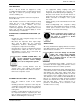
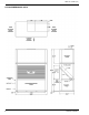
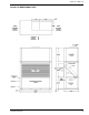
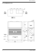
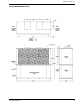
FORM 145.15-IOM7 (412) GENERAL INFORMATION All models are shipped as factory-charged unitized packages. All models are designed for freestanding mounting on the floor, or on a field fabricated structural steel stand. All models are shipped with vertical evaporator fan discharge as standard. The evaporator fan discharge configuration is field convertible on all units. To ensure safe installation of the unit when ceiling mount application is specified, estimate the approximate center of gravity of the unit.
FORM 145.15-IOM7 (412) UNIT MOUNTING The 5 ~ 20 ton models are shipped as a fully assembled integral package. If required units may be field split to allow for passage through doors, elevators, hallways, etc. Duct flanges for evaporator return are incorporated into the filter rack. Units should be secured on a solid, level pad or sturdy stand. The use of an isolating rubber sheet is recommended to reduce vibration and noise transmission.
FORM 145.
FORM 145.
FORM 145.
FORM 145.
FORM 145.15-IOM7 (412) DUCTWORK When installing ductwork, adhere to local Codes and sensible practice. Minimize duct runs and avoid abrupt changes in direction where possible. Allow ample access space for servicing of the coils and changing of filters. Perform regular maintenance on ducts to increase unit life, maintain efficient operation, and reduce accumulation of explosive dust.
FORM 145.15-IOM7 (412) ELECTRICAL WIRING Follow local electrical codes when making electrical connections. Units are completely factory wired for normal supply voltages (ie.208-230, 460, 575V/3Ph/60Hz) Confirm unit specifications by checking unit data plate. All electrical components are accessible through an independent electrical panel located on the right hand end of the evaporator/compressor section. The electrical control boxes are located behind outer access panels.
FORM 145.
FORM 145.
FORM 145.
FORM 145.
FORM 145.15-IOM7 (412) ELECTRICAL DATA ELECTRICAL DATA - STANDARD EVAPORATOR MOTOR MODEL # EVAPORATOR FAN COMPRESSOR VOLTAGE QTY RLA LRA HP FLA MIN. CCT. AMPACITY MAX FUSE / CCT. BKR. AMP CSV060B2 208-230/3/60 1 @ 16.0 110.0 1.00 3.1 23.10 35 CSV060B4 460/3/60 1 @ 7.8 52.0 1.00 1.5 11.25 15 CSV060B5 575/3/60 1 @ 5.7 38.9 1.00 1.2 8.33 15 CSV096B2 208-230/3/60 2 @ 13.1 83.1 1.50 4.5 33.98 45 CSV096B4 460/3/60 2 @ 6.1 41.0 1.50 2.2 15.
FORM 145.15-IOM7 (412) FAN PERFORMANCE CSV060B SUPPLY AIR BLOWER PERFORMANCE SUPPLY CFM AVAILABLE EXTERNAL STATIC PRESSURE - Inches W.C. ¹ 0.2 0.4 0.6 0.8 1.0 1.2 1.4 1.6 1.8 2.0 RPM BHP RPM BHP RPM BHP RPM BHP RPM BHP RPM BHP RPM BHP RPM BHP RPM BHP RPM Field Supplied Low Static Drive Standard Drive + 1 HP BHP Optional Hi-Static Drive + 1.5 HP 1600 645 0.29 733 0.36 814 0.43 888 0.50 958 0.57 1024 0.64 1087 0.72 1154 0.83 1211 0.91 1245 0.99 1800 708 0.40 788 0.48 863 0.55 933 0.
FORM 145.15-IOM7 (412) CSV180B SUPPLY AIR BLOWER PERFORMANCE SUPPLY CFM AVAILABLE EXTERNAL STATIC PRESSURE - Inches W.C. ¹ 0.2 0.6 0.4 0.8 1.0 1.2 1.4 1.8 1.6 2.0 RPM BHP RPM BHP RPM BHP RPM BHP RPM BHP RPM BHP RPM BHP RPM BHP RPM BHP RPM Field Supplied Low Static Drive Standard Factory Drive + 3 HP BHP Optional Hi-Static Drive + 5 HP 4800 634 1.20 697 1.42 757 1.62 813 1.84 867 2.06 918 2.30 5400 701 1.66 758 1.90 812 2.14 864 2.38 914 2.62 962 2.88 1009 3.12 1053 3.38 1097 3.
FORM 145.15-IOM7 (412) MOTOR AND PULLEY DATA EVAPORATOR-STANDARD BLOWER MOTOR AND DRIVE DATA Adjustable Motor Motor Pulley Drive Model Range Pitch Browning Frame Eff. (RPM) Dia. HP Size (%) (in) Part No. CSV060B 745-1117 1 CSV096B 614-921 CSV120B 711-984 CSV180B CSV240B 1.9-2.9 1VP34X7/8 Blower Pulley Pitch Browning Dia. (in) Part No. 1.5 145 88.5 1.9-2.9 1VP34X7/8 5.7 AK59H AX35 2 145 88.5 2.4-3.4 1VP40X7/8 6.4 AK66H AX37 724-925 3 184 90.2 3.4-4.4 1VP50X1 1/8 8.
FORM 145.15-IOM7 (412) BLOWER SPEED ADJUSTMENT The RPM of the supply air and condenser air blowers will depend on the required CFM, and the static resistances of both the supply/discharge and the return/intake duct systems. With this information, the RPM for the blowers can be determined from the blower performance tables. Adjustment of blower speed is accomplished as follows: 1) Loosen belt tension by moving motor towards the blower shaft via the adjustable mounting.
FORM 145.
FORM 145.15-IOM7 (412) START-UP AND OPERATION Start unit and check rotation of fans and compressors. Scroll compressors will only compress in one rotational direction. Three phase compressors will rotate in either direction depending upon phasing of the power. Since there is a 50-50 chance of connecting power in such a way as to cause rotation in the reverse direction, it is important to ensure proper rotation direction is achieved when the system is installed and operated.
FORM 145.15-IOM7 (412) MICROPROCESSOR CONTROLLER The microprocessor control system is specifically designed for single and dual stage systems. The control system interfaces with a conventional type thermostat. • Unit shall be complete with self-contained lowvoltage control circuit • Unit shall incorporate a lockout circuit which provides reset capability at the space thermostat or base unit, should any of the following standard safety devices trip and shut off compressor.
FORM 145.15-IOM7 (412) described above), the microprocessor control board will continue to monitor the low-pressure limit switch for any openings. If the low-pressure switch opens for greater than 5 seconds, the microprocessor control board will de-energize the compressor, initiate the ASCD, and stop the fan. If the call for cooling is still present at the conclusion of the ASCD, the microprocessor control will reenergize the compressor.
FORM 145.15-IOM7 (412) Current alarms or active restrictions are flashed on the microprocessor control LED. 1. LAST ERROR – When this button is pressed and released, it flashes the last five (5) flash codes on the board’s LED. The most recent alarm is shown first and the oldest alarm is shown last. 2. TEST RESET – When this button is pressed and released, any anti-short cycle delays (ASCD) are bypassed for one cycle. When pressed twice, any active lockouts are reset. 3.
FORM 145.15-IOM7 (412) MAINTENANCE / SERVICE DRIVE BELT DISCONNECT AND LOCK OUT POWER WHEN SERVICING UNIT. FAILURE TO DO SO MAY RESULT IN PERSONAL IN-JURY OR DEATH DUE TO ELECTRICAL SHOCK. Exercise care when working around the sharp metal edges of door panels or door frames, etc. These edges can cause injury. EVAPORATOR COIL Inspect the evaporator coil at filter change intervals. Dirty or clogged evaporator coils causes low suction pressure and lost capacity.
FORM 145.15-IOM7 (412) R-410A QUICK REFERENCE GUIDE Refer to Installation Instructions for specific installation requirements. • R-410A Refrigerant operates at 50 - 70 percent higher pressures than R-22. Be sure that servicing equipment and replacement components are designed to operate with R-410A. • R-410A Refrigerant cylinders are rose colored. • Recovery cylinder service pressure rating must be 400 psig. DOT 4BA400 or DOT BW400. • Recovery equipment must be rated for R-410A.
FORM 145.15-IOM7 (412) Subject to change without notice. Printed in U.S.A. Copyright© 2012 by Unitary Products Group. All rights reserved. Engineered Systems Products Group Form 145.15-IOM7 (412) P.O.