
Install Instructions

2 Actuator Literature—D-3153 with Auxiliary Mounting Bracket Installation Bulletin
G
eneral
The D-3153 with auxiliary mounting bracket is
designed for use with small dampers primarily on
multizone units. This kit is used where swivel
mounting is required and/or space limitations inhibit the
use of the standard universal mounting bracket. The
swivel mounting feature reduces the side load on the
shaft bearing to provide smooth operation.
The D-3153 pneumatic actuator is designed for use
with UL leakage rated dampers in smoke control
applications up to 250°F (121°C). All models are UL
component recognized. Two models have a factory
installed and calibrated D-9502 Positioner for
proportional volume control applications.
All models incorporate several internal and external
features that add functional flexibility:
●
A 2-way swivel connection on the actuator cylinder
provides non-binding movement to compensate for
damper alignment conditions.
●
All actuators have a telescoping piston rod for
easy linkage to the damper for attachment points
up to 8-3/4 inches (222 mm) away from the face of
the actuator.
●
A swivel ball joint and slotted crank arm connector
are furnished for optional methods of linkage to the
damper.
●
A stop screw kit is available for special applications
to limit the power stroke of the actuator when
required.
IMPORTANT: For safety dampers, copper
tubing must be used between the
actuator and the controller. The
tubing must be looped at the
actuator so that pivoting of the
actuator does not cause stress
on the tubing.
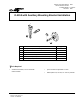
M
ounting
Pivot Post
A uxiliar
y
Mountin
g
Bracket
Piston Rod Extension
Set Screw
Swivel Ball Joint
S wivel H ead
Crank Arm
3
Figure 1: Mounting Components
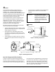
Pivot Post
Auxiliar
y
Mountin
g
Bracket
7-7/8
(
200
)
5-9/16
(
141
)
4
(
102
)
11-5/8
(
295
)
D-9502 Positioner
Position A
2-15/16
(
75
)
Position B
3-25/32
(
96
)
Figure 2: Mounting Dimensions
Special Linkages and Offset Surfaces
In order to achieve the desired mounting bracket
location, it may be necessary to extend the piston rod.
This can be done by loosening the set screw on the
shaft extension hex nut and telescoping the piston rod.
If the actuator axis is perpendicular to the drive shaft,
the normal crank arm radius of 2-1/8 inches (54 mm)
will result in a 90° shaft rotation with a 3 inch stroke.
If the actuator axis is at a moderate angle to the drive
shaft, the crank arm radius will need to be adjusted in
order to achieve a 90° shaft rotation.