
Install Instructions
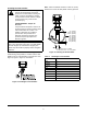
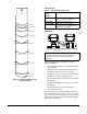
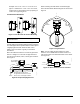
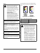
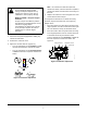
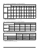
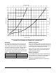
Table Of Contents

F261 Series Flow Switches Installation Instructions
Refer to the QuickLIT website for the most up-to-date version of this document.
1
Applications
The F261 Series Flow Switches respond to fluid flow in
lines carrying water, ethylene glycol, or other
nonhazardous fluids. These models also work in
applications with swimming pool water and lubricating
oils.
F261 Series Standard Flow Switches use a variety of
paddle sizes to respond to fluid flow rates in
applications with 1 inch trade size (or greater) pipe.
F261 Series Low Flow Switches respond to low fluid
flow rates in applications with 1 inch trade size (or less)
pipe.
A low-energy model with gold-plated contacts provides
improved electrical performance in low-voltage, low-
current circuits to operate small relays, solenoid valves,
and electronic control circuits.
Installation
F261 Series Standard Flow Switches are packaged
with 1 in., 2 in., 3 in., and 6 in. stainless steel flow
paddles along with a paddle screw and lock washer.
See Table 2 for replacement parts.
IMPORTANT: Do not install or use this F261 Series
Flow Switch in or near environments where
corrosive substances or vapors could be present.
Exposure of the F261 Series Flow Switch to
corrosive environments may damage the device’s
internal components and will void the warranty.
IMPORTANT: Do not use F261 Series Flow
Switches where the fluid in the pipes drops below
the fluid’s freezing point, causing an internal
freeze-up.
IMPORTANT: Use this F261 Series Flow Switch
only as an operating control. Where failure or
malfunction of the flow switch could lead to personal
injury or property damage to the controlled equipment
or other property, additional precautions must be
designed into the control system. Incorporate and
maintain other devices, such as supervisory or alarm
systems or safety or limit controls, intended to warn of
or protect against failure or malfunction of the flow
switch.
IMPORTANT : Utiliser ce F261 Series Flow Switch
uniquement en tant que dispositif de régulation.
Lorsqu'une défaillance ou un dysfonctionnement du
flow switch risque de provoquer des blessures ou
d'endommager l'équipement contrôlé ou un autre
équipement, la conception du système de contrôle
doit intégrer des dispositifs de protection
supplémentaires. Veiller dans ce cas à intégrer de
façon permanente d'autres dispositifs, tels que des
systèmes de supervision ou d'alarme, ou des
dispositifs de sécurité ou de limitation, ayant une
fonction d'avertissement ou de protection en cas de
défaillance ou de dysfonctionnement du flow switch.
F261 Series Flow Switches
Installation Instructions
Part No. 24-7664-2969, Rev. D
Issued March 2016