
Install Instructions
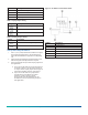
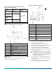
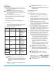
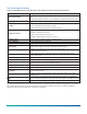
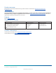
Table Of Contents

Table 3: Jumper positions with HL-6900 used as a
proportional override device
System
controller
Input jumper
position
Output jumper
position
Air handling
unit
0 mA to 20 mA
DX-9xxx or
AS‑LCPx00-0
Digital control
module via an
FM‑OAE
0 VDC to 10 VDC
System 350 with
a W351P
0 mA to 20 mA or
0 VDC to 10 VDC
User selectable.
See Figure 1.
Generic User selectable
Figure 3: HL-6900 using a system controller
Callout Description
A HL-6900 Device
B Power
C 24 VAC transformer
D System controller
E Common
F Input
G Humidification equipment
H Output
Mounting
About this task: To mount the humidity device, see
Figure 4, and proceed as follows:
Figure 4: Mounting and assembly
Number Description
1 Housing
2 Duct
3 Nut for conduit fitting, not provided
4 Conduit hole
5 Washer, cupped side towards housing
6 Conduit fitting, not provided
7
Two 8 in. x 1 in. Phillips-head sheet
metal screw
8 Snap-on cover
9
Conduit knockout, top and bottom of
cover
1. Remove any excess insulation from the duct that
prevents the probe from extending a minimum of 3
in. (76 mm) into the air stream.
2. Use the hole saw to make a 1 in. (25.4 mm)
diameter hole in the duct for inserting the probe.
3. Pull the plastic cover off the housing.
4. Insert the probe into the duct, and mark the
location of the holes for the mounting screws.
5. Remove the unit, and drill a 1/8 in. (3 mm) hole for
each mounting screw.
Important: Remove the unit before drilling to
prevent any metal remnants from falling onto
the circuit board. Seal any holes created during
installation to help reduce drafts and ensure
accurate sensor readings.
6. Use a gasket, sealer, or other means to seal the
area around the 1 in. (2.54 mm) hole between the
unit and the duct.
7. Reinsert the probe, and secure the housing to the
duct using the two No. 8 screws provided.
HL-6900 Multi-function Humidity Device with Temperature Sensor Installation Guide 3