
Install Instructions
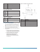
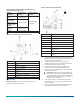
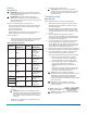
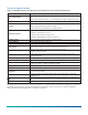
Table Of Contents

Wiring
About this task:
CAUTION: Risk of Electric Shock. Disconnect the
power supply before making electrical connections
to avoid electric shock.
ATTENTION: Risque de décharge électrique.
Débrancher l'alimentation avant de réaliser tout
raccordement électrique afin d'éviter tout risque de
décharge électrique.
Observe the following when wiring the unit:
• Do not run low voltage wiring in the same conduit as
line voltage wiring or other conductors that supply
highly inductive loads.
• Use 18 to 24 AWG wire.
• Make all wiring connections in accordance with the
National Electrical Code and local regulations.
To wire the device:
1. Route the wires from the controller to the HL- 6900
Device through the conduit hole in the housing.
See Table 4 for wiring terminal details.
Table 4: Wiring information
Terminal
Terminal
designation
Polarity
Source and
destination
1 Power +
From the
system
controller or
a separate
24 VAC
transformer
2 Common -
For power,
input, and
output
3 Input +
0 mA to 20 mA
or 0 VDC to
10 VDC from
the system
controller
4 Output +
To
humidification
equipment
5
6
Temperature N/A
1K ohm nickel
temperature
sensor
7
8
Relay N/A
For ON/OFF
humidity
equipment
2. Break out the plastic knockout on the cover with
pliers to accommodate the wiring or conduit. See
Figure 4.
Important: If you use a conduit fitting (not
provided), use the washer provided to support
the fitting in the housing. If you do not use
the washer, the fitting could stress the plastic
housing.
3. Make wire connections to the appropriate screw
terminals. See Table 4.
4. Press the cover onto the base.
Important: Check all connections before
applying power to the system. Short circuited
or misconnected wires could permanently
damage the unit.
Troubleshooting
About this task:
If the humidity device is not functioning properly:
1. Make sure the power supply is functioning and
wired properly to the device. Check the output
wiring connections.
2. If the HL-6900 Device is not delivering an output,
check the jumper positions and make sure they
are appropriately selected for the application. See
Figure 1.
3. If the humidification equipment is cycling
excessively, the proportional band setting may be
too low. Set the proportional band potentiometer
to a higher value. See Figure 1
4. If room humidity never reaches the desired level,
the HL-6900 device’s setpoint may be set too
low. Gradually raise the setpoint and monitor the
results. Make sure the setpoint is not too high, or
excess moisture could collect in the duct.
5. Verify that the system controller operates properly.
Refer to the appropriate controller documentation.
6. If the HL-6900 device’s output is still inaccurate
after performing Steps 4 and 5, record the
proportional band setting and proceed as follows:
a. Measure duct humidity with a humidity
measuring device, such as an optical dew
point hygrometer, and record the result.
b. Measure the output of the HL-6900 Device
using a Digital Volt Meter (DVM) or a
Milliampere (mA) meter, and record the
result.
c. Measure the system controller’s output, the
input to the HL-6900, using the DVM or the
mA meter, and record the result.
Note: If the duct humidity is below the
proportional band, the HL-6900 device’s output
should be equal to the system controller’s
output. If the duct humidity is above the
proportional band, the HL-6900’s output should
be 0 VDC (0 mA).
Note: If the duct humidity is inside the
proportional band, calculate the HL-6900’s
output as follows:
Note: X is either 10 VDC or 20 mA, depending
on the application.
HL-6900 Multi-function Humidity Device with Temperature Sensor Installation Guide4