
user manual


898841-UIM-B-0113
10 Johnson Controls Unitary Products
1. Remove the front panel.
2. Open the front panel upward and pull it toward you.
3. Remove the terminal cover and cord clamp.
4. Insert the connecting cable (according to local codes) into the pipe
hole on the wall.See Figure 11.
5. Pull the connecting cable through the cable slot on the rear case so
that it protrudes about 6 inches (~15 cm) out of the front.
6. Connect the ground wire to the ground terminal of electrical box.
7. Insert the connecting cable fully into the terminal block and secure it
with screws while making sure no part of its core is visible. Make
sure you don't mis-wire the unit. See Figure 12.
8. Firmly tighten the terminal screws to prevent them from getting
loose.
9. Secure the connecting cable with the cord clamp.
10. Attach the terminal cover and front panel on the indoor unit.
SECTION XII: PIPE FORMING AND DRAIN
PIPING
PIPE FORMING
Interchange the drain cap and the drain hose.
1. Place the drain hose below the refrigerant piping.
2. Make sure the drain hose is not bent or kinked.
3. Do not pull the hose when applying the tape.
4. When the drain hose passes the room, be sure to wrap field-pro-
vided insulation material around it.
5. In the case of bending refrigerant piping, keep the following precau-
tions in mind to avoid abnormal sounds that may be generated if
improper work is conducted.
a. Do not press the refrigerant pipes onto the bottom frame.
b. Do not press the refrigerant pipes on the front grille.
Mis-wiring could damage unit or cause communication errors
between indoor and outdoor unit.
TABLE 10:
Wire Color Reference
Color Code Color
Color Code or
Symbol
Color
WH White BN Brown
YE Yellow BU Blue
RD Red BK Black
YEGN Yellow Green
FIGURE 11: Indoor Unit Wall Mounting Bracket
Be sure to refer to the wiring system diagram labeled inside the front
panel.
Check local electrical regulations for any specific wiring instructions
or limitations.
WALL
WIRING
FIELD PROVIDED
PVC WALL SLEEVE
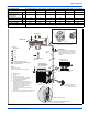
FIGURE 12: Indoor Electrical Wiring Connections
FIGURE 13: Drain Piping Outlets Option
GROUND
WIRE
TERMINAL BLOCK
TERMINAL COVER
SCREW
SCREW
CORD CLAMP
CONNECTING CABLE
TERMINAL BLOCK
YELLOW-GREEN
BLUE
BROWN
BLACK
CONNECTING
CABLE
ABOUT 5.9”
2.8”
0.39”
GROUND
LINE
0.39”
1.97”
RIGHT
REAR RIGHT
RIGHT DOWNWARD REAR LEFT
LEFT DOWWARD
LEFT