
user manual

898841-UIM-B-0113
Johnson Controls Unitary Products 15
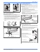
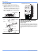
REFRIGERANT PIPING CONNECTIONS
A Service port cap protects the service port core from contamination
and serves as the primary leak seal. To access service port:.
1. Remove service port cap with an appropriate sized wrench.
2. Connect gauge set to service port.
3. When testing is complete, replace service port cap and tighten as
follows:
a. With torque wrench - Finger tighten then torque cap per Table 11
requirements.
b. Without torque wrench - Finger tighten then use appropriate
sized wrench to turn an additional 1/6 turn clockwise.
Stem cap protects the valve stem from damage and serves as the pri-
mary seal. Replace the stem cap and tighten as follow:
1. With torque wrench - Finger tighten and use torque cap per Table
11.
2. Without torque wrench - Finger tighten then use an appropriate
sized wrench to turn an additional 1/12 turn clockwise.
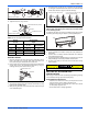
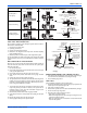
INDOOR UNIT CONNECTION
• Connect both liquid and gas pipes to indoor unit.
• Apply a sealing cap or water-proof tape to prevent dust or water
from getting into the refrigerant piping before it is connected.
• Apply a thin coat of refrigerant oil on the seal surface of the pipe.
• For connection, first align the union tube and flared refrigerant
line with each other then tighten the flare nuts lightly at first to
obtain a smooth match.
• Use tightening toque Table 11 as a guideline for indoor unit side
union joint section and tighten using two wrenches. Excessive
tightening may damage the flare section.
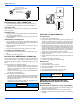
OUTDOOR UNIT CONNECTION
• Apply a sealing cap or water proof tape to prevent dust or water
from getting into the refrigerant piping before it is connected.
• Apply refrigerant lubricant to the matching surfaces of the flared
line set and union before connecting them together. This will
reduce refrigerant leaks.
• Align the flared refrigerant line with valve connection then tighten
the flare nut lightly at first to obtain a smooth match. Use tighten-
ing toque Table 11 as a guideline.
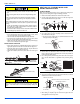
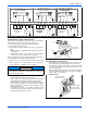
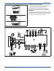
FIGURE 32: Outdoor Unit Wiring Terminal Designations
OUTDOOR UNIT
TERMINALS
N(1)
23
L1 N
(DATA)
(NEUTRAL)
(GND)
N(1)
2
3
(NEUTRAL)
(GND)
(L1)
N(1)
23
L1 L2
(DATA)
(L2)
(GND)
N(1)
2
3
(GND)
(L1)
N(1) 2 3
N(1)
2
3
L1
L2
(L2)
(GND)
(L1)
(GND)
208-230V SYSTEMS
30 & 36 KBTU (208-230V)
SYSTEM ONLY
115V SYSTEMS
INDOOR UNIT TERMINALS
INDOOR UNIT TERMINALS
INDOOR UNIT TERMINALS
OUTDOOR UNIT
TERMINALS
OUTDOOR UNIT
TERMINALS
OUTDOOR UNIT
TERMINALS
(NEUTRAL)
(NEUTRAL)
(DATA)
• Fasten flare nut with a torque wrench as specified in Table 9.
• When fastened too tight, flare nut may break after a long period
and cause refrigerant to leak.
NOTICE
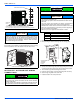
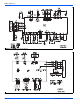
FIGURE 33: Indoor/Outdoor Piping Connections
FIGURE 34: Outdoor Line Set Connections
MALE FLARE
CONNECTION
APPLY REFRIGERANT
LUBRICANT HERE
A
B
OUTDOOR UNIT
LIQUID SIDE PIPING
(SMALLER DIAMETER)
TORQUE WRENCH
GAS SIDE PIPING
(BIGGER DIAMETER)