
Install Instructions
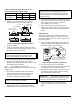
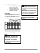
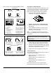
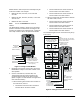
Table Of Contents

Installation Instructions M91xx
Issue Date September 2017
© 2017 Johnson Controls 1
Part No. 34-636-399, Rev. P www.johnsoncontrols.com
34- 636- 399, Rev . P
M9108, M9116, M9124, and M9132 Series
Electric Non-Spring Return Actuators
Installation
IMPORTANT: Use this M9108, M9116, M9124,
or M9132 Series Electric Non-Spring Return Actuator
only to control equipment under normal operating
conditions. Where failure or malfunction of the
actuator could lead to personal injury or damage to
the controlled equipment or other property, additional
precautions must be designed into the control
system. Incorporate and maintain other devices,
such as supervisory or alarm systems or safety or
limit controls, intended to warn of or protect against
failure or malfunction of the actuator.
IMPORTANT: Utiliser ce M9108, M9116,
M9124, or M9132 Series Electric Non-Spring Return
Actuator uniquement pour commander des
équipements dans des conditions normales de
fonctionnement. Lorsqu'une défaillance ou un
dysfonctionnement du actuator risque de provoquer
des blessures ou d'endommager l'équipement
contrôlé ou un autre équipement, la conception du
système de contrôle doit intégrer des dispositifs de
protection supplémentaires. Veiller dans ce cas à
intégrer de façon permanente d'autres dispositifs,
tels que des systèmes de supervision ou d'alarme,
ou des dispositifs de sécurité ou de limitation, ayant
une fonction d'avertissement ou de protection en cas
de défaillance ou de dysfonctionnement du actuator.
Parts Included
All Models
• M91xx Series actuator
• M9000-160 anti-rotation bracket
• two No. 12-24 x 1/2 in. self-tapping hex
washer-head screws
M9124- and M9132-AGA Models
Includes one M9000-105 pluggable 3-terminal block.
M9124- and M9132-AGD and AGE Models
Includes two M9000-105 pluggable 3-terminal blocks.
M9124- and M9132-AGC Models
Includes three M9000-105 pluggable 3-terminal blocks.
Special Tools Needed
• torque wrench with 10 mm socket
• digital voltmeter
Mounting
IMPORTANT: The actuator is intended for
indoor mounting only, with no direct exposure to
water beyond NEMA 2 conditions. Use an
appropriate shield or enclosure where the
environment exceeds NEMA 2 specifications.
Mount M91xx Series actuators in any convenient
orientation. Install the actuators on a 3/8 to 3/4 in.
(9.5 to 19 mm) round shaft or a 3/8 to 5/8 in.
(9.5 to 16 mm) square shaft, 2 in. (51 mm) or longer.
If the shaft is less than 2 in. (51 mm) long, install an
extension recommended by the damper or valve
manufacturer. Use the M9000-154 1 in. Jackshaft
Coupler Kit for 1 in. (25.4 mm) outside diameter shafts.
To mount the actuator, proceed as follows:
1. Press and hold the gear release lever, and rotate
the coupler to the 0 or 90° position. Release the
gear release lever. (See Figure 1.)
U-bolt
with
Clamp
Nuts (2)
Shaft Center
Coupler
Gear
Release
Note: A
is the distance from the center of the
holes in the anti-rotation bracket to the center
of the shaft. (See Table 1.)
Anti-Rotation
Bracket
A
3
0
9
0
0
6
0
0
3
0
6
0
9
0
Figure 1: Mounting Positions