
Install Instructions
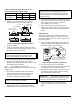
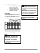
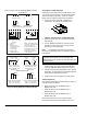
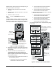
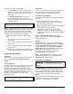
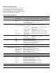
Table Of Contents

2 M9108, M9116, M9124, and M9132 Series Electric Non-Spring Return Actuators Installation Instructions
Table 1: Shaft Sizes and Distances from the
Anti-Rotation Bracket to Shaft Center
Shaft Diameter
5/8 in.
1/2 in.
3/8 in.
A Dimensions
6-1/8 in. 6-3/16 in. 6-1/4 in.
(See Figure 1.)
(155 mm)
(157 mm)
(159 mm)
2. Bend or cut the anti-rotation bracket to fit the
damper frame or duct as shown in Figure 2.
No. 12-24 Sheet
Metal Screws (2)
Slot for Bracket
Anti-Rotation Bracket
Damper
Frame
Anti-Rotation
Bracket Tab
Cover Screw
Figure 2: Anti-Rotation Bracket Positions
3. Close the damper.
4. Insert the anti-rotation bracket tab into the slot at
the bottom of the actuator (shown in Figure 2), and
slide the actuator onto the shaft.
IMPORTANT: The tab on the anti-rotation
bracket must fit midpoint in the actuator slot to
prevent actuator binding and premature wear.
5. Use the anti-rotation bracket as a guide, and drill
the holes in the damper frame or duct for the
bracket (using dimension A shown in Figure 1 and
the measurements in Table 1).
Note: When installing the actuator to a
Johnson Controls damper, use the existing holes in the
damper frame.
6. Attach the anti-rotation bracket to the damper
frame or duct with the two self-tapping screws
provided, using a 1/4 in. (7 mm) flat-blade
screwdriver or 5/16 in. (8 mm) nut driver.
IMPORTANT: Do not overtighten the mounting
screws to avoid stripping the threads.
7. Slide the actuator onto the damper shaft,
positioning the tab on the anti-rotation bracket
midway into the slot at the bottom of the actuator.
IMPORTANT: For Variable Air Volume
applications that use an M9108 Series actuator,
secure the coupler to the shaft with the damper in
the fully open position to avoid damaging the open
position end-stop.
8. Hold the actuator in place, and evenly hand tighten
each clamp nut onto the U-bolt. Secure the U-bolt
to the damper shaft to achieve a torque of
100 to 125 lb∙in (11 to 14 N∙m).
9. Press and hold the gear release. Rotate the
coupler fully closed to fully open to verify that the
damper and actuator rotate freely throughout the
range.
Rotation Range
The actuator is factory set for 0 to 90° rotation. To
change the rotation range to less than 90°, use the
top scale on the actuator cover, refer to Figure 3, and
proceed as follows:
1. Press and hold the gear release, and rotate the
actuator coupler Counterclockwise (CCW) to the
0° position. Release the gear release.
Position
Indicator
Gear
Release
Coupler
CCW
Note: The locking clip is factory
set at the missing tooth of the
actuator hub for 90° rotation.
0
0
3
0
6
0
9
0
9
0
3
0
6
0
Locking
Clip
Back of the
Actuator
Hub
Figure 3: M91xx Actuator Components
2. Turn the actuator over. Use a flat-blade
screwdriver to release the locking clip, and remove
the coupler from the front of the actuator.
3. Reinsert the coupler into the front of the actuator,
and align the position indicator with the starting
point of the desired rotation range.
IMPORTANT: Advancing the coupler 90° from
the factory setting prevents the actuator from driving
in either the Clockwise (CW) or CCW direction.
4. Push the coupler into the actuator until the
locking clip snaps over the hub, securing it in
place.