
Install Instructions
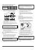
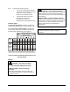
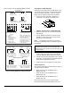
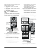
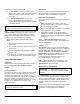
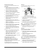
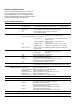
Table Of Contents

4 M9108, M9116, M9124, and M9132 Series Electric Non-Spring Return Actuators Installation Instructions
Refer to Figure 5 for the applicable M91xx actuator.
Models AGA, AGC, AGD, and AGE
On/Off Control
24 VAC
24 VDC
1 2 3
COM CW CCW
^
-
~
+
~
+
24 VAC
24 VDC
1 2 3
COM CW CCW
~
+
~
+
^
-
Floating Control
0-20 mA
0-20V
0-10V
~
+
24V
++
++
1 2 3 4 5 6
^
-
Proportional Control
Models:
GGA, GGC, HGA,
and HGC
1 = Common
2 = Power
3 = Calibration Out
(for HGA and HGC
models only)
4 = Current Input
5 = Voltage Input
6 = Feedback Output
100-10K ohms
0-10V
~
+
24V
^
-
^
-
1 2 3 4 5 6
COM
CCW CW
+
+
+
Resistive Input Control
Models: JGA and JGC
Note: Terminals 3 and 4
function as CCW and CW
references when the
Resistive models are in
the DA mode but as CW
and CCW references
when these models are
in the RA mode.
Terminal Block 1
Models: M9124 and M9132
AGD = 0 to 135 ohms
AGE = 0 to 1000 ohms
CW
0%
100%
Wiper (W) CCW CW
Feedback Potentiometer
Auxiliary Switches
(Shown Factory Set)
Models: M9124- and
M9132-AGC
C1 NC1 NO1 C2 NO2 NC2
Switch
S1
Switch
S2
10° 80°
(Shown Factory Set)
Models: M9108- and
M9116-AGC
Switch
S1
Switch
S2
10° 80°
NC
NO NCNO
21 22 23 24 25
Models: M9108 and M9116
AGD = 0 to 135 ohms
AGE = 0 to 1000 ohms
CW
0%
100%
11 12 13
Terminal Block 2
Figure 5: Wiring Diagrams for M91xx Models
Through the Conduit Openings
Depending on the M91xx Series model selected, use
one or both conduit openings. The threaded actuator
conduit openings accept 1/2 in. trade size conduit
fittings. Refer to Figure 6 and proceed as follows:
1. Loosen the cover screw with a Phillips No. 1
screwdriver, and remove the actuator cover.
Plugs
(Conduit Openings)
Cover
Screw
Figure 6: Location of the Conduit Openings
2. Push the plastic plug out of the conduit opening
with fingertip.
3. Use the Phillips screwdriver to puncture a hole
through the center of the plug, and reinsert the
plug into the conduit opening.
Note: For applications requiring metal conduit,
thread the conduit fitting into the conduit opening and
hand tighten.
IMPORTANT: Use flexible metallic tubing or its
equivalent with the fitting. Do not overtighten the
conduit fitting into the actuator to avoid damaging the
actuator threads.
4. Insert the cable wires through the plastic plug or
conduit fitting, and connect to the terminal block
using the applicable wiring diagrams in Figure 5.
5. Perform the procedures appropriate to the specific
application, as described in the Tandem Operation
and Setup and Adjustments sections.
6. Reattach the cover and tighten the cover screw.
Tandem Operation
The tandem configuration provides twice the torque of
a single actuator as follows:
• 280 lb∙in (32 N∙m) for two M9116-GGx or
M9116-HGx units
• 420 lb∙in (48 N∙m) for two M9124-GGx or
M9124-HGx units
• 560 lb∙in (64 N∙m) for two M9132-GGx or
M9132-HGx units
The actuators operate in exact synchronization,
ensuring the load is split evenly between each unit.