
Install Instructions
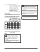
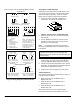
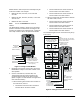
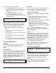
Table Of Contents

M9108, M9116, M9124, and M9132 Series Electric Non-Spring Return Actuators Installation Instructions 5
Models with the same torque and control input may be
mounted in tandem. For example:
• M9116: two GGx, two HGx, or one GGx and
one HGx
• M9124: two AGx, two GGx, two HGx, or one GGx
and one HGx
• M9132: two AGx or two GGx
Note: Do not use M9108 Series models in
tandem.
The Master/Slave Jumper is factory set in the master
position. Determine the method for mounting the two
actuators in tandem: front-to-back (Figure 7 shows the
front view) or back-to-back, and proceed as follows:
Common
CW
CCW
Terminal 101
Terminal 102
Terminal 103
Master/Slave
Jumper
(Shown in the
Master Position)
Spade Terminals for
Feedback Potentiometer
on AGD or AGE and
Auxiliary Switches on AGC
(See Figure 5.)
Terminal Block 1
Terminal Block 2
Figure 7: Settings on AGx Models
1. Designate one actuator as the master, and move
Master/Slave Jumper on the other actuator to the
slave position.
2. Connect Terminal 101, Terminal 102, and
Terminal 103 from the master actuator to the
corresponding terminals on the slave actuator.
(Refer to Figure 7 for AGx models and Figure 8 for
GGx and HGx models.)
a. When mounting two actuators front-to-back on
the same shaft, connect:
• Terminal 101 from the master actuator to
Terminal 101 on the slave actuator.
• Terminal 102 from the master actuator to
Terminal 102 on the slave actuator.
• Terminal 103 from the master actuator to
Terminal 103 on the slave actuator.
b. When mounting two actuators back-to-back on
the same shaft, connect:
• Terminal 101 from the master actuator to
Terminal 102 on the slave actuator.
• Terminal 102 from the master actuator to
Terminal 101 on the slave actuator.
• Terminal 103 from the master actuator to
Terminal 103 on the slave actuator.
The total wire length for these connections may be up
to 30 ft (9 m).
Auxiliary Switches
(See Figure 5.)
1 Common
2 Power
3 Calibration Ouput
(HGx Models Only)
4 Current Input
5 Voltage Input
6 Feedback Output
Span Potentiometer
Zero Potentiometer
Note:
Jumpers W1, W2, W3, and W4
have no effect when the actuator
is in the Slave mode.
Master/Slave Jumper
(Shown in the
Master position)
Terminal
Block 1
101 102 103
1 2 3 4 5 6
Jumper W2
Factory Set
Voltage Input
0 to 10 VDC
Current Input
Feedback Ouput
0 to 20 mA 4 to 20 mA
2 to10 VDC
* HGx Models Only
Fixed
Jumper W3*
Factory Set
Adjustable
Jumper W1
Direct Acting (DA)
Reverse Acting (RA)
Rotation Direction with
Increasing Signal
Factory Set
(CCW) RA
(CW) DA
Feedback Output
Factory Set
Voltage Input
Jumper W4
Note:
For current input,
set Jumper W4
in the 0 to 10 VDC
position.
101
Terminal
Block 1
103102
Figure 8: Settings on GGx and HGx Models