
Install Instructions
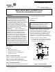
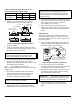
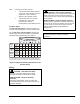
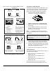
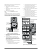
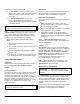
Table Of Contents

6 M9108, M9116, M9124, and M9132 Series Electric Non-Spring Return Actuators Installation Instructions
3. Connect the input control signal:
• For AGx models, connect the input control
signal to the common, CW, and CCW terminals
on both the master and the slave actuators.
(See Figure 7.)
• For GGx and HGx models, connect the
control signal to the master actuator, and
connect 24 VAC/VDC power to both the master
and slave actuators.
IMPORTANT: For proper tandem operation, do
not connect the control input to the slave unit.
Note: Set the master actuator jumpers on the GGx
and HGx models according to the action and signal
range desired before proceeding. (Refer to Figure 8
and the Setup and Adjustments, Calibration section.)
4. Make sure of the following if the actuators
configured for tandem operation stall or fail to
drive:
a. Both actuators have the same torque and
control input.
b. One actuator is set as the master and the other
as the slave.
c. The control signal is connected to the master
actuator only.
d. Terminal 101, Terminal 102, and Terminal 103
are connected properly, as described in Step 2.
Setup and Adjustments
Calibration
Calibrate only the actuator designated as the master
when using two AGx, GGx, or HGx models in
tandem.
Direction of Action
In the DA mode (factory set), a minimum control signal
drives the actuator to the full CCW position, and a
maximum control signal drives it fully CW. In the
Reverse Acting (RA) mode, a minimum control signal
drives the actuator to the full CW position, and a
maximum control signal drives it fully CCW. To set an
actuator for RA, proceed to the section for the
appropriate model.
IMPORTANT: Adjust the rotation range before
changing the direction of action.
AGx Models
To set one of these models for RA operation, reverse
the control wiring connections at Terminal 2 and
Terminal 3. (See Terminal Block 1 in Figure 5.)
GGx, HGx, and JGx Models
To set one of these models for RA operation, proceed
as follows:
1. Press and hold the gear release, rotate the
actuator coupler until it is in the full CW position,
and release the gear release.
2. Move Jumper W1 from the factory-set DA position
to the RA position. (See Figure 8.)
3. Apply power and then a control signal to the
actuator to verify that the actuator is fully CW at
minimum control input, and fully CCW at maximum
control input.
Note: HGA and HGC models may require
potentiometer settings. Proceed to the Potentiometer
(HGx Models) section.
Jumpers
AGx models come factory set with the Master/Slave
Jumper in the master position and have no additional
jumpers. GGx, HGx, and JGx models come factory
set with Jumper W1 in the DA position. GGx and
HGx models have additional jumpers factory set as
follows: Jumper W2 is in the 0 to 10 VDC or
0 to 20 mA position, and Jumper W4 is in the
0 to 10 VDC position. (See Figure 8.)
Note: HGx models have an additional jumper,
Jumper (W3), factory set in the fixed position. The
AGx models do not have jumpers.
Potentiometers (HGx Models)
IMPORTANT: Adjust both zero and span
potentiometers for full actuator travel and complete
calibration.
The HGx models have zero and span potentiometers
that do not require adjustment when Jumper W3 is
factory set in the fixed position. When Jumper W3 is in
the Adjustable (ADJ) position, without waiting for the
actuator to drive to the final position, proceed as
follows:
Adjust the zero and span potentiometers using either
Terminal 3 and Terminal 5 or Terminal 3 and
Terminal 4, a control signal, and a voltmeter.