
Install Instructions
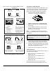
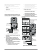
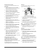
Table Of Contents

M9108, M9116, M9124, and M9132 Series Electric Non-Spring Return Actuators Installation Instructions 7
Adjusting the Zero and Span
To adjust the zero and span potentiometers on the
HGx models:
1. Verify that Jumper W2 is in the 0 to 10 VDC
position, and provide 24 VAC or 24 VDC power to
Terminal 1 (Common) and Terminal 2.
2. Connect the Common from the controller to
Terminal 1, and either a voltage signal to
Terminal 5 or a current signal to Terminal 4.
3. Connect Terminal 1 and Terminal 3 to a voltmeter
to monitor the calibration output.
4. Use a 1/8 in. (3 mm) flat-blade screwdriver to turn
the zero potentiometer fully CW and the span
potentiometer fully CCW.
5. Apply the minimum (zero point) control signal
required for positioning the actuator at the
minimum position.
6. Monitor DC calibration output. To adjust the
zero potentiometer, turn it CCW until the voltmeter
displays 0 V or slightly less.
7. Adjust the control signal to the maximum voltage
desired to cause full rotation.
8. Monitor the calibration output at Terminal 1 and
Terminal 3. Adjust the span potentiometer CW to
increase the calibration output to 10 V.
9. Verify that the actuator is properly calibrated by
adjusting the control signal to the minimum and
maximum levels.
Example for a zero of 3 VDC and a span of 5 VDC:
• Apply a 3 volt control signal to the actuator, and
turn the zero potentiometer CCW until the
calibration output at Terminal 3 is 0 V.
• Apply maximum voltage. (In this case, it is 8 VDC,
which results in a span of 5 volts.)
• Monitor calibration output at Terminal 3, and adjust
the span potentiometer CW to 10 V.
Auxiliary Switches (xGC Models)
The M91xx-xGC models have two built-in
auxiliary switches that allow setting at any angle
between 0 and 90° (factory set for 10 and 80°,
nominal). Refer to the Technical Specifications section
for auxiliary switch ratings.
The following procedures serve as examples to
change the position of the auxiliary switch angles:
Switch S1
To change the angle of Switch S1 to 20°, refer to
Figure 9 and proceed as follows:
Nodule Guides
(10° Increments)
Gear Release
0°
90°
Plunger
Position
Indicator
CCW
Edge of
Switch S1
Edge of
Switch S2
CW
Figure 9: Switch Angle Settings
1. Depress the gear release, and using the 0 to 90°
nodule guides, rotate the coupler until the position
indicator is at 20°.
2. Loosen the screw on Switch S1 with a
Phillips No.1 screwdriver.
3. Rotate Switch S1 CCW, and align the edge of the
switch with the plunger until the plunger rises.
Note: The normally closed contact closes, and the
normally open contact opens. (See Auxiliary Switches
in Terminal Block 2 of Figure 5.)
4. Retighten the Phillips-head screw on Switch S1,
while holding it in the designated position.
Switch S2
To change the angle of Switch S2 to 70°, refer to
Figure 9 and proceed as follows:
1. Depress the gear release, and using the 0 to 90°
nodule guides, rotate the coupler until the position
indicator is at 70°.
2. Loosen the screw on Switch S2 with a
Phillips No. 1 screwdriver.
3. Rotate Switch S2 CW, and align the edge of the
switch with the plunger until the plunger rises.
Note: The normally closed contact opens, and the
normally open contact closes. (See Auxiliary Switches
in Terminal Block 2 of Figure 5.)
4. Retighten the Phillips-head screw on Switch S2,
while holding it in the designated position.
5. Depress the gear release, and rotate the coupler
until the position indicator is back to 0°.